


rlb
-
Posts
655 -
Joined
-
Last visited
Content Type
Profiles
Forums
Gallery
Events
Everything posted by rlb
-
 OC, The monstrous alligator clip in the previous post was a shocking reminder of the scale of this. Nice work. Ron
 -
Thanks, Steve. I try to set a high bar for myself, but I am far from a perfectionist. I am pleased that the model comes across well. The willingness to do things over (at least some of the time and to a point) is something you have to have in this hobby. To think that you'll get everything right the first time is unrealistic. Great that you received your Oneida, and I hope you are planning to start a build log. I would love to watch (and help when I can) another version of this ship take shape. There are a few out there and they are all different. The 1/4" Chapelle plans are beneficial. How much so depends on how far you want to take the model beyond Dave's kit. Rigging for example--if you're not rigging it you obviously don't need the sail plan. If you are going for the fine points, I think the hull plan helps a lot. Dave was very faithful to Chapelle's plan, but there are small differences, and some details left out. I think this was to make a slightly simpler model, that worked with what the kit supplied, as is the case with most kits. The 1/4" drawings are just nice to have also, though being simple B&W copies, they aren't as visually rich as the British museum plans of those ships! Good luck! Ron
-
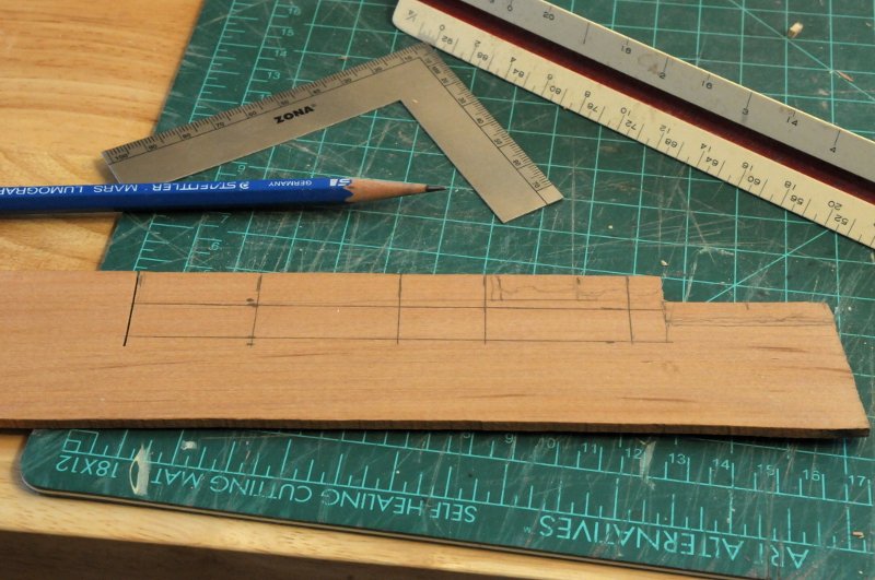
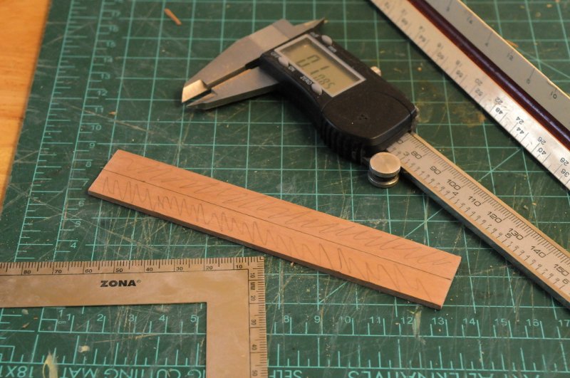
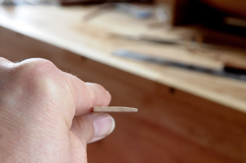
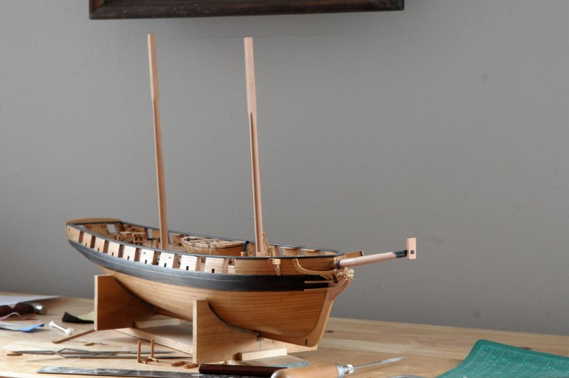
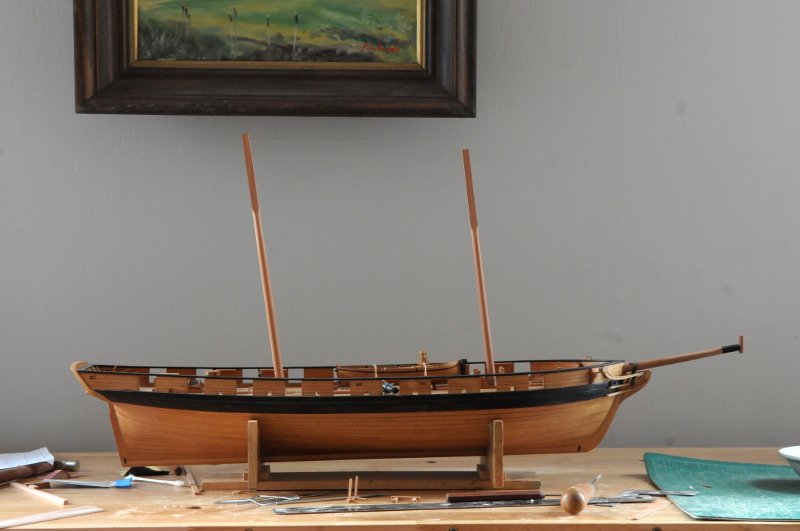
Thanks, Roger. I feel more connected to this model than I might another, because the ship was built and sailed in my "neck of the woods". Work now commences on the channels. I marked the rough sizes on some wood stock-- I cut the overall piece out, and sanded it to approximate maximum thickness of about 5". It will eventually need to be 4.5" on the sides that meet the hull, but I like to give myself some leeway initially. I re-marked the center line, which will be the hull side when the individual channel pieces are cut out, and scribbled on each side of the centerline. These areas need to taper down to about 2 1/2" at the edges. I sand them on a piece of sandpaper laid flat on the table, using finger pressure to create the bevel. The centerline marking and scribble help make sure I am not sanding the center-- Here is progress on one side, a little more to go-- I think in hindsight it would have been better to make a single long strip, so to only have to sand one bevel. Next time. In order to correctly angle the chainplates, I need the masts in place to run a "dummy" shroud down to the channels and use it to successively mark the angle of each chainplate and notch in the channel. Here are the masts temporarily fitted-- I haven't measured the exact rake angle, this is just by eye, looking at the sail plan. I will be sure to do that before marking the chainplates-- Ron
-
Bob, Great job. It's very interesting to see someone with your skill level bringing a sensibility--the weathering and real world coloring--that one tends to see in plastic, but not as much in wooden (ship) modeling. Those photos taken outside from earlier in your log are especially effective. Ron
-
I hope we all have that little boy feeling! Ron
-
Ciciak35, I enjoy reading you building log. Your enthusiasm is wonderful! Keep up the good work. I hope you and your wife are able to stay healthy. Ron
-
Thanks for the kind words, Dan and Ed, I really appreciate it. Stuglo, I just hand push them. At first I was using dressmakers pins which are thinner than the T-shaped pins (at least the ones I have). They wouldn't stick in the holes very well. Then, when I switched to the T-pins, since the holes I had drilled were smaller than the T-pins, they worked very well, at least for a while, maybe 5 or 6 "pushes". When the hole gradually got enlarged by repeated use of the pin, I again had problems. So what I learned was, drill your hole (at the receiving location, not the item you are pinning through) just smaller than the pin. Ron
-
Jean-Paul, You're work is impeccable. I have one question--why do you tint the filler, if you will paint over it? Ron
-
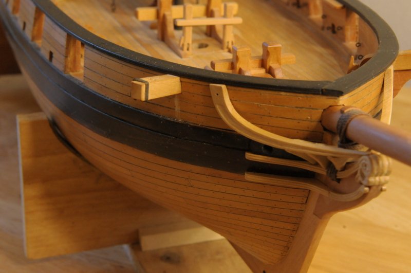
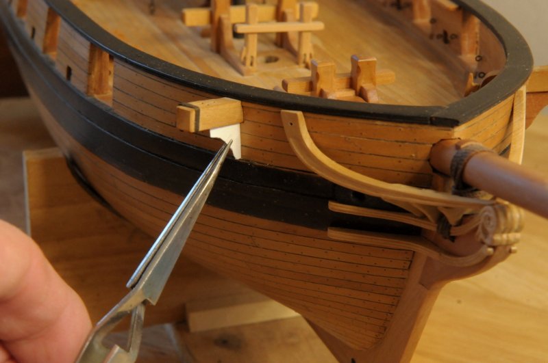
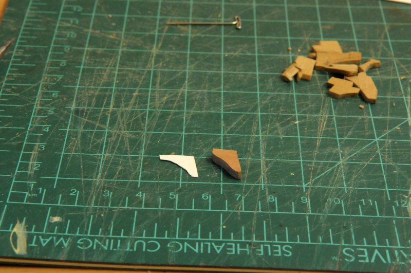
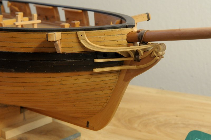
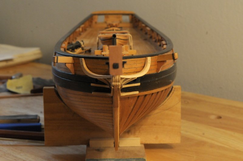
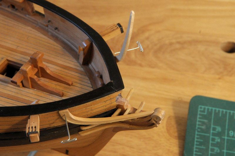
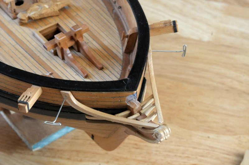
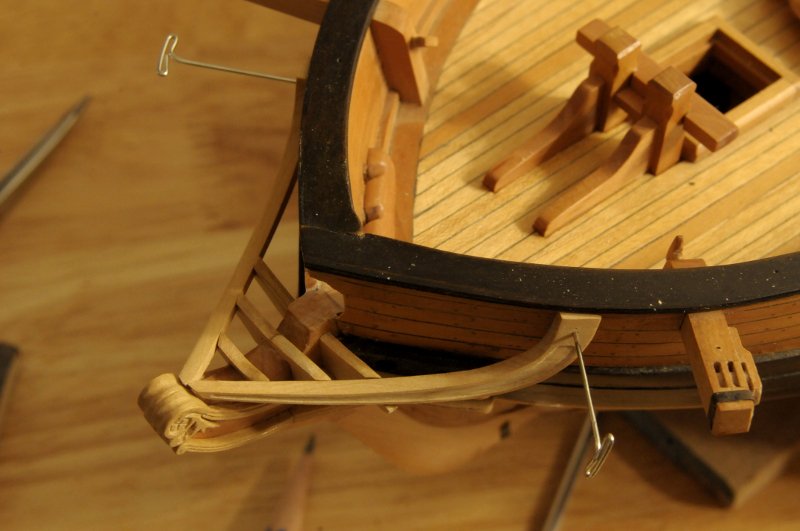
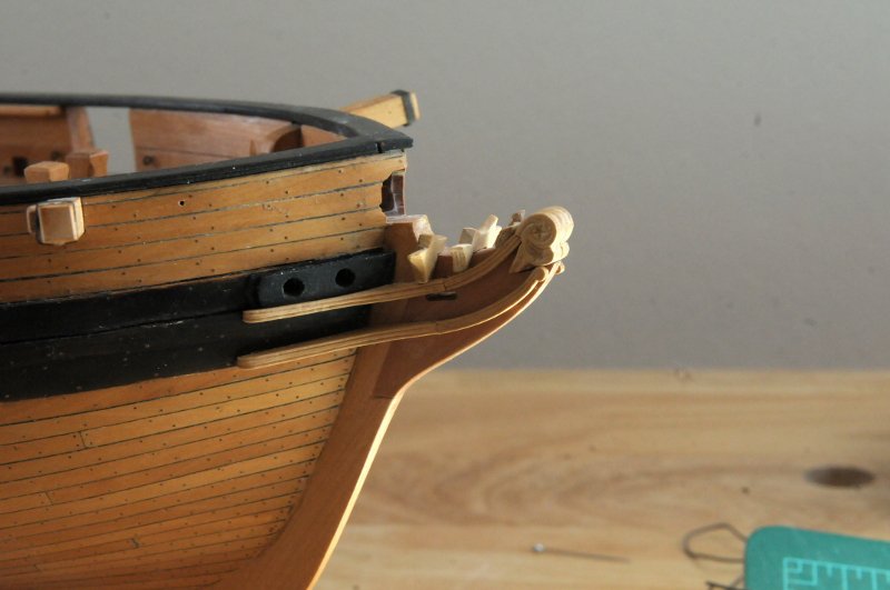
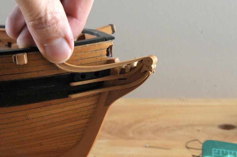
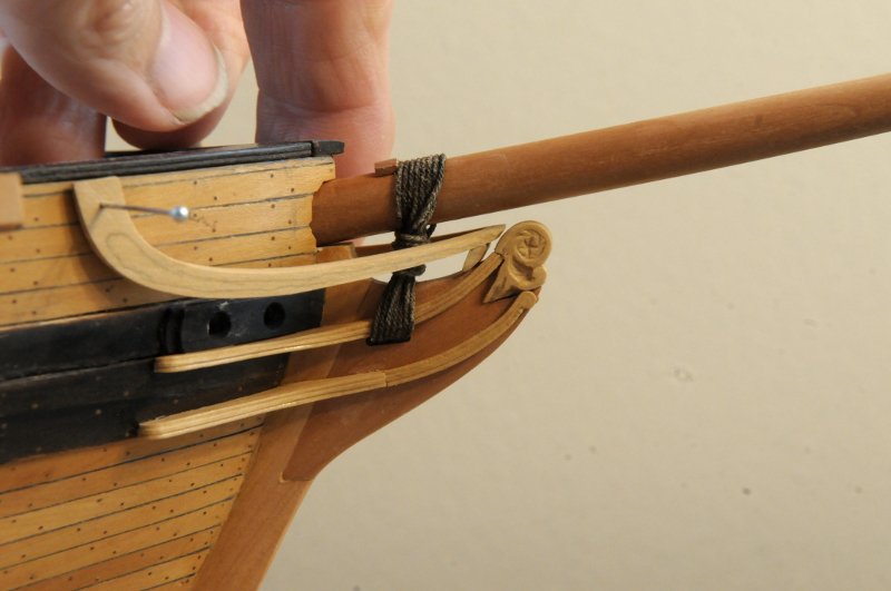
Thanks Dan. I appreciate you checking in and supplying help and information! I'm sure I made the head rails and timbers harder to make than they should have been. I did as you suggested, cut the timbers to match the rails. Making the angled and sloped notches in the ends of the timbers was the hard part. Getting those angles correct, at the right height to meet the headrail, and still making sure the other end of the timber was square and the right height on the stem was a challenge. I think the version of timbers you posted would have been easier (except for the multiple rail aspect!) I don't think I found the best technique in making mine this first time around. Maybe I should have made card patterns, though being only two dimensional, they wouldn't have helped with all the devilish angles. Or maybe I just need more practice at it. As far as straddling the stem (or as I probably should be calling it, the knee of the head), It looks like some did and some didn't, depending on the various configurations, size of ships, time periods, etc. David's FFM shows timbers that straddle for the Swan class, which are the ones I more or less tried to follow. In any event, I have stuck a fork in them, and they are done. Here they are removed, in order to reinstall the bowsprit-- They are in two pieces, with the timbers glued to the headrails, reminding me of chicken bones-- Here the bowsprit and gammoning have been re-attached, and the headrail assemblies glued. I've scratched the finish under the cathead, for a support that needs to go there-- Fitting a card pattern-- The horizontal leg needed to be shortened, the pattern didn't account for the cat rope that threads through a hole inboard of the sheaves in the cathead-- Here it is installed. What a relief to work on something not as frustrating as the head timbers!-- Here's a straight on bow shot-- Next order of business will be the channels and deadeyes, though at some point I should buckle down and work on the installation of the carronades. The one I have done you see askew on the deck. Ron
-
Work continues on the head timbers. I've made the decision (at least for now) to omit the most forward tiny timber. The second timber, which is one piece and straddles the stem is now my starting point. Surprisingly, making some trims to the port headrail made the two headrails join more symmetrically than they had before, and there was no modification needed to that second (now the first) timber-- I worked on the remaining starboard timbers, and with some adjustments, I was able to keep them. This is so much easier without the bowsprit in the way-- The port side is another matter entirely-- The last timber is way off, and the second may be close, but I'm going to redo it to have it close that gap between it and the starboard one. The join won't be on the centerline, but it will be better than the current gap. Another view showing the terrible unevenness of the port side timbers. Here it looks like the second one is the worst offender, but the problems are pretty much shared between the second and third-- The second and third were redone, and it's getting close now-- Ron
-
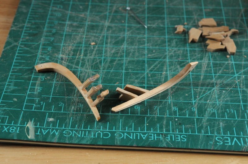
Hi Martin, Pins seem to be the preferred/recommended way to hold pieces, but when I have tried, as you said, the pieces slip and spin, or the pins fall out. I do pin the aft end of the headrail in place quite often when I'm testing the fit of the timbers. I have trouble getting the pin to stay in place without pushing it so hard that I'm afraid of breaking something. I'm going to try small bits of PA glue on the timbers, that seems to work okay for me. I made the difficult decision to remove the gammoning and bowsprit. It really gets in the way. I have also been thinking that my gammoning rope should have been just a little smaller diameter. It was close to what I had researched it should be, maybe just a bit on the heavy side. The next size I have is just a bit on the light side, but I think it will look more correct, and will also not crowd the head timbers as much. My plan is to get the head timbers and rail to fit right, take them back off, reinstall the bowsprit and gammoning, and then permanently glue the rails and timbers. We'll see how that goes. So off comes the gammoning-- I optimistically carved the second timber with the decorative panels-- Glued the first two timbers, and the starboard half of the third-- And test fit the rail-- As you can see, I've got some problems. It looks clear that the notch in the second timber is too low. This may or not be so--it could be that the notch in the third is too high. It had seemed that way when I was trying to do this before taking the gammoning and bowsprit off. At this point I am not sure if it's worth using any of these timber pieces, or if they should all be redone. More testing is in order. Ron
-
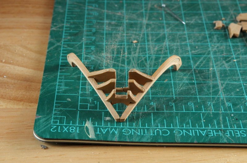
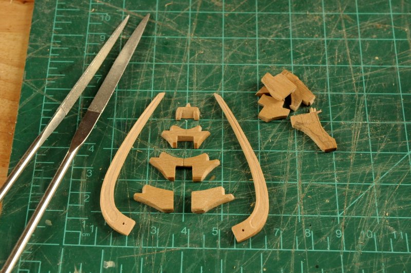
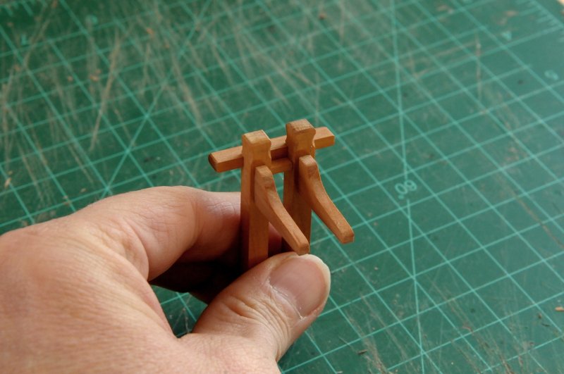
Thanks Dan. Ah, more tools to buy! Does it ever end? The head timbers have all been cut out, and shaped. A handful that didn't make it are on the right. I still have to carve the decorative panels on the lower faces. That has been done on the smallest one, but you can't see it from this angle-- These have all been dry fit individually, and I would like to dry fit the whole assembly before I glue it all up, but I have no idea how to keep them all in place. I may have to lightly glue, and then take them off and re-glue permanently when it's good to go. Ron
-
Hi smotyka, Thanks for your comment, and best of luck with your Oneida! My experience with L u m b e r y a r d is that sometimes they are slow, but they come through. I remember it taking a few months to get mine. You'll find that once you get beyond the hull framing, you're kind of on your own. There used to be a couple of Oneida's on MSW besides mine, but they may not have survived the website melt-down in 2013. I made a lot of changes to the deck layout as shown on the drawings that come with the kit. Don't be afraid to ask questions, and I would love to see you start a build log. Ron
-
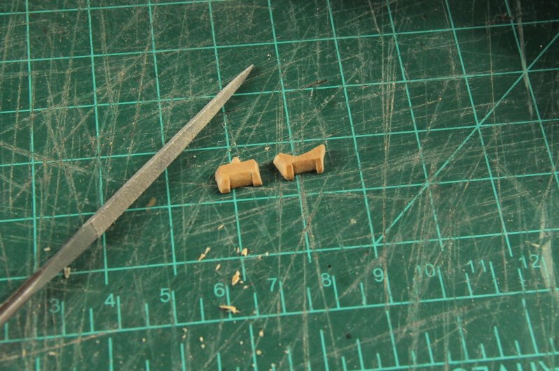
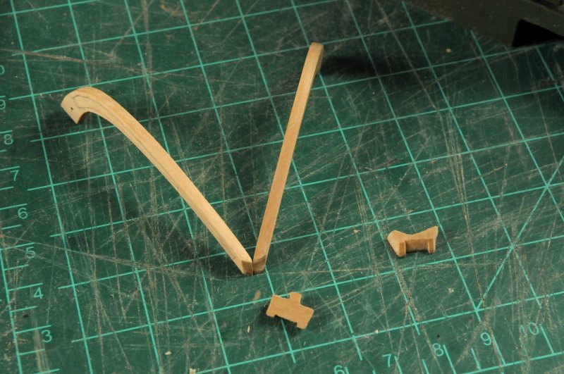
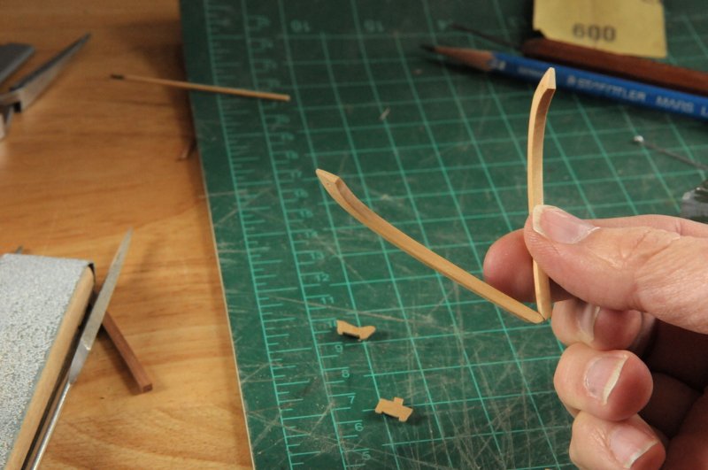
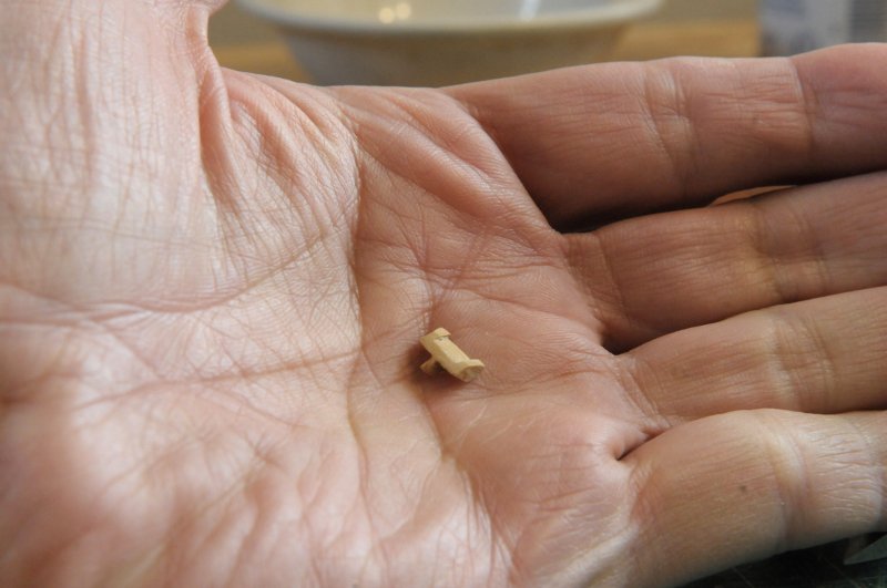
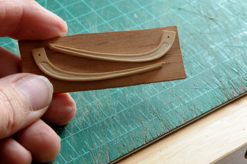
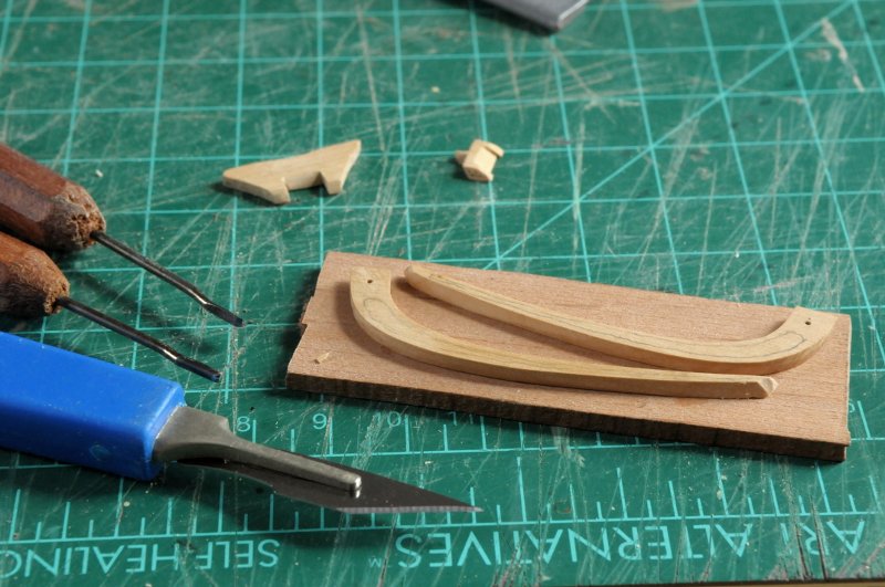
Thanks Sam. I will try that out next time I need to ebonize. Good to know Martin. I see your text got auto changed also--unless you did that on purpose! Strange. I am now working on the head timbers. The farthest one forward is tiny. I have a strong feeling that this piece wouldn't be anything like what I am trying to make, but I am putting it where it shows on the Chapelle plan. There are four timbers shown, and if I keep that number, and the spacing, this is what I get. It is very small on the draft. On the right is one that I started, then quickly realized it wasn't even going to be close. The one on the left, with the little triangular bit on top (that fits between where the rails come together) is the shape I get when I start to fit it with the head rails on the stem-- And in order to hold things together while I check the fit, I have temporarily glued the head timbers together-- An early fit shows that the timber, small as it is, is too tall, and I think the headrail is also too thick at this point-- So I sanded some off the headrails, and continued to work on the tiny timber piece. The next fitting is getting closer, I need to work on the bottom of it, as it's not sliding down on the stem and sitting on the hair bracket properly-- Now it fits about the way it should--in it's messed up way. If I were a real perfectionist, I would do the billet head again, a little taller (now that the bowsprit angle has been adjusted upward), so that timber wouldn't have to be so ridiculously tiny-- It's really small-- Now that that piece is done, I unglued the head rails from each other, and again temporarily glued them, this time flat, so I could carve the relief pattern in them. The second timber is starting to be roughed out. It will have a more typical shape-- Here are the head rails carved. I am not an experienced carver, and the camera emphasizes all the imperfections. I may try to smooth the inner area of the lower one, which is starboard, because that's the side that I was thinking to have more visible when I display the model. I carved the port side second, so naturally it came out a little bit better-- Ron
-
Stuglo, the bowsprit and masts won't have the rope bands on this ship. They are small enough to have been single pieces, not "made" masts built up of many pieces and thus needing the bands. So no hiding! Yes, "it's only a model" is a very irritating comment. Sam, yes the iron gall mixture reacts to the tannin in the Quebracho bark extract, and to a lesser extent in the wood itself. Both parts are watery, so they leach into the wood fibers, which causes the stain to bleed or "creep". The masking doesn't seem to help much. Martin, I got my Swiss Pear from Dave at the L u m b e r y a r d. (I had to space that out because when I tried to post, something converted the word to "a wood supplier". For whatever reason this site changed the text, I hope I am not violating some protocol by mentioning his business) That was at least 7 years ago. His website is still up, but I do not know if they are still in business. (I hope so, because I do not know where else to buy modelling wood stock now.) Ron
-
Jean-Paul, That hand-painted transom looks so good, you should consider hand painting the friezes. Ron
-
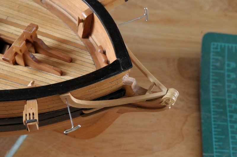
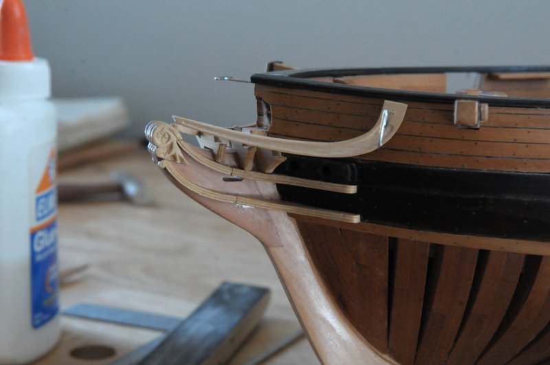
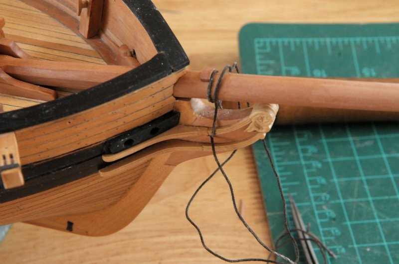
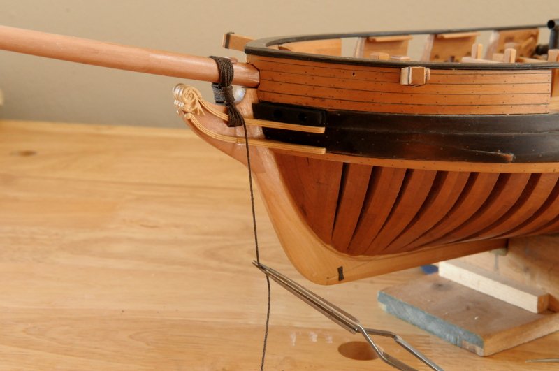
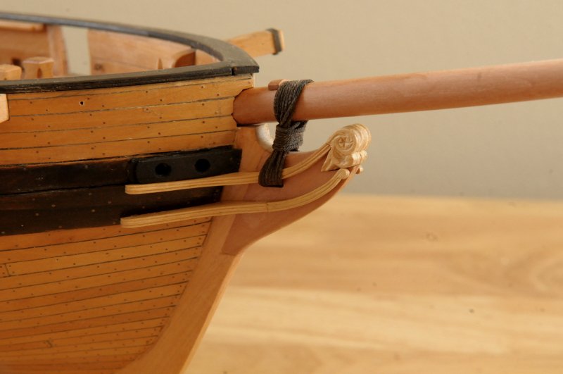
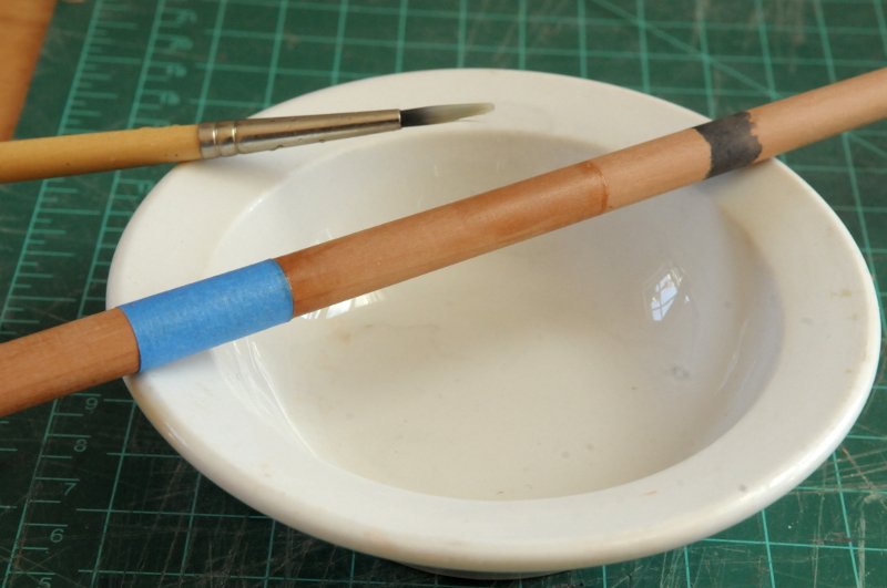
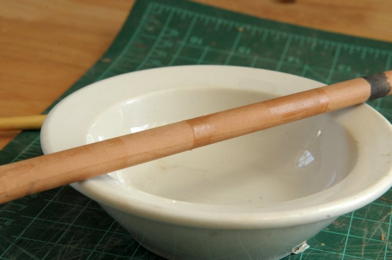
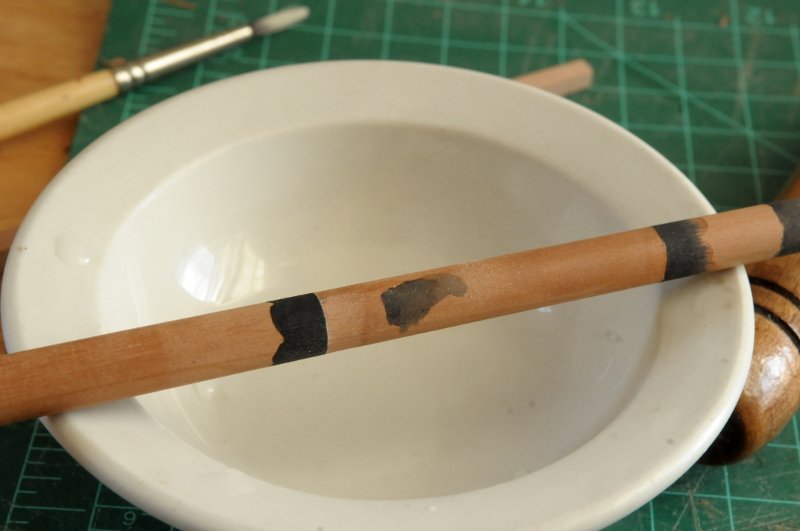
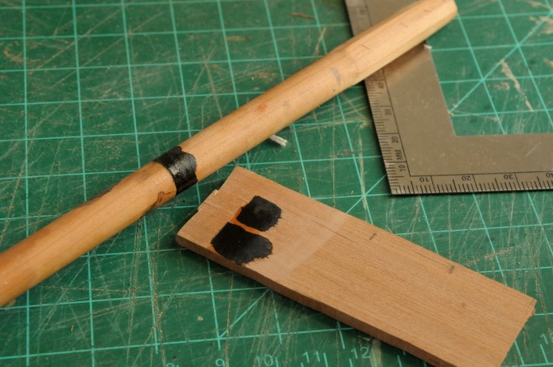
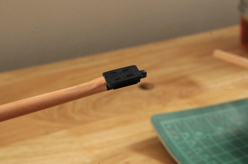
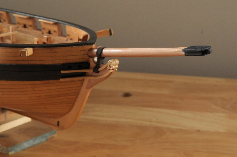
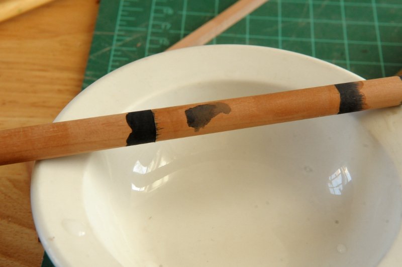
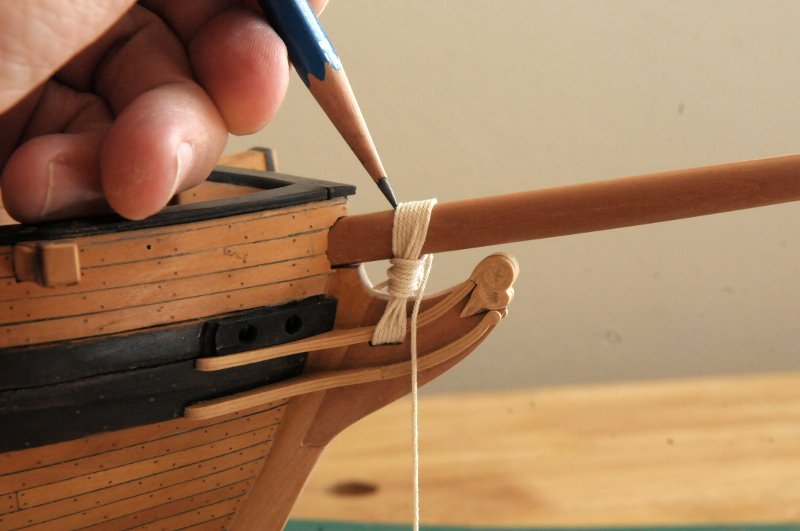
Thanks, stuglo. Well, six years ago I was right here! If only you had found the site earlier. I have great admiration for all those who worked at this ship modeling pre-internet, or at least pre MSW, as you have done. Though I've always loved ship models, I had never even considered trying to build one--I wouldn't have even known where to start. Then one day I saw a friend's Canoe that he had built from a Midwest kit. Pre-internet I suppose I probably would have learned from him where a brick and mortar store was to buy the kits, gotten some advice, etc., and probably have given up on the first try. Instead, Google was here, and so am I. The Coronavirus precautions have shut down my office today, so I was able to spend some time modeling. Here's the gammoning work-- The bowsprit bitts have been glued in, and the bowsprit is now permanently attached. I didn't glue the bowsprit to anything, but with the gammoning done it's not going anywhere. No sooner did I do this than I regretted it. Now I have to blacken the forward part of the bowsprit in place, and I'm worried about how my ebonizing is going to work where I have to have a clean line dividing the blackened from unblackened area. Here is my discarded earlier mast attempt, now being used for experimentation. On the far right is my first try. I used some masking tape (removed at this point), and blackened up to the edge of the masking tape. Unlike paint, which lays on the surface, the ebonizing seeps into the wood. That part of the photo is a little out of focus, but sure enough, the blackening seeped under the masking tape. In the middle is an attempt where I am going to use the Tung Oil finish to perhaps seep into the wood and make a barrier. The same thing on the left, only here I have added some masking tape so that when I take it off before staining, the Tung Oil will have formed a sharper line, with a slight "lip"-- Neither of those attempts worked. The masked version was the worst. Though curiously, the left side of that one, where I didn't care (and there was no Tung oil finish!), had almost no noticeable bleeding!! The attempt on the right side of the photo was better as far as the clean line I was trying to achieve--very little bleeding (though it was also against the Tung Oil finish!), but I hadn't managed to paint a very straight line. I wasn't sure what to learn from this!-- The staining doesn't go deep into the hard pear wood, so I tried filing off the seeped areas-- That worked okay, but unfortunately there was some re-seepage when I tried applying some Tung Oil finish which was about half diluted with mineral spirits. [I am considering this after all has been done--maybe the Tung Oil finish, especially when diluted, has the effect of "pulling" the stain. Though why didn't it do that on the right test?] Thinking about how that back edge had turned out so well, made me try to duplicate it. I thought it might have been because I didn't try to paint right up to the line with the second part of the blackening mixture, and it had just floated in, meaning that I hadn't brushed the second application to that line, it had just mixed with the "pool" of the first liquid in that area, and that it somehow didn't bleed. Below on the flat wood, the right side is where I tried to duplicate the floating in of the blackening , but at the middle/left, where it mattered, one little blip still bled. After this, on the left, I tried cutting a line with a knife to try and give a hard edge, and maybe limit the seepage, and again floated the second solution into the first, instead of painting with the brush up to the line. This pretty much worked. Then I tried covering this with the more viscous, undiluted, Tung Oil Finish to see if it would stay okay. I didn't get additional seepage. (That is also what is shown reapplied to the earlier attempt on the mast.) I seemed to have some clues to a technique that might work. [More experiments were surely warranted, but sadly not carried out because truly I am more hasty and impulsive than scientific]-- My technique on the bowsprit is going to be: 1) Incise a line 2) Paint the first part of the blackening (the Quebracho extract liquid) up to the line 3) Float in the second part (the rusty iron solution), and hope for the best. Undiluted Tung Oil finish after. This all would have been so much easier if I hadn't attached the bowsprit first. Here incising the line-- Here blackened-- It worked pretty well, just that one little spot aft of the bees where I went astray with the application of the first part. I used a knife to (mostly) shave that away-- It's not perfect, but it's done. You can also notice where I had applied finish to the inner part of the bowsprit before I did the gammoning. The blackened part now also has a coat of finish, but the rest of the bowsprit does not. I still need to attach some things to it-- I have more of this partial blackening to do on the masts. Hopefully I'll improve my technique. Why not be done and just paint it? Part of it is the challenge I guess, but I also don't want these black areas to look different, in color or sheen, than the ones I've already done on the hull. And all that, from the bitts to the bees, was so I could do the gammoning prior to finishing the headrails. That's next. Ron
-
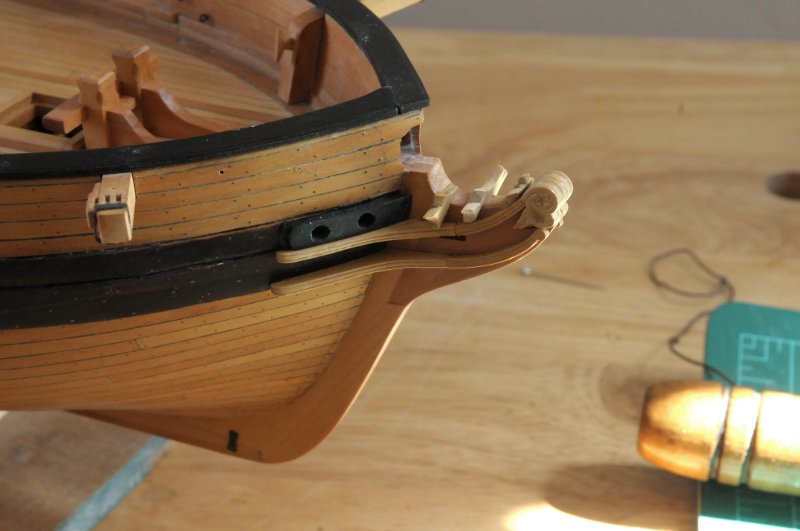
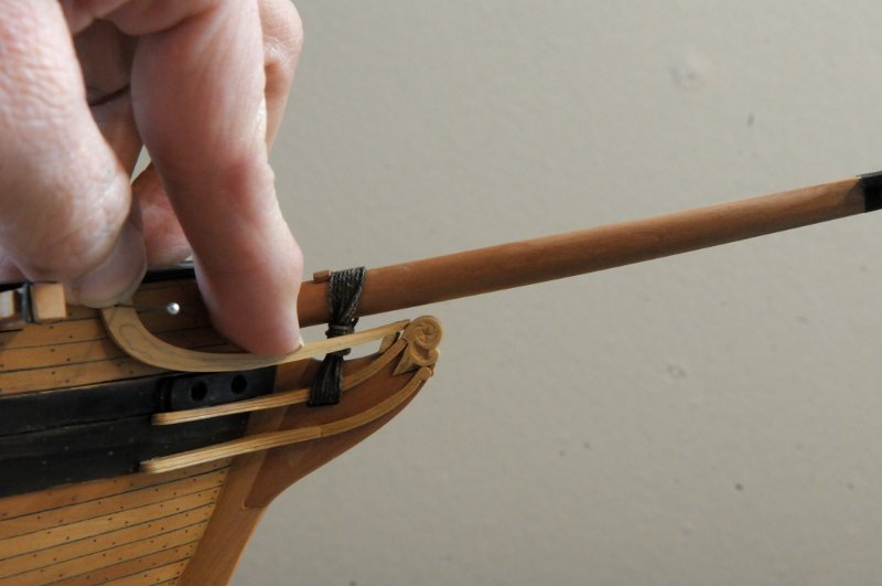
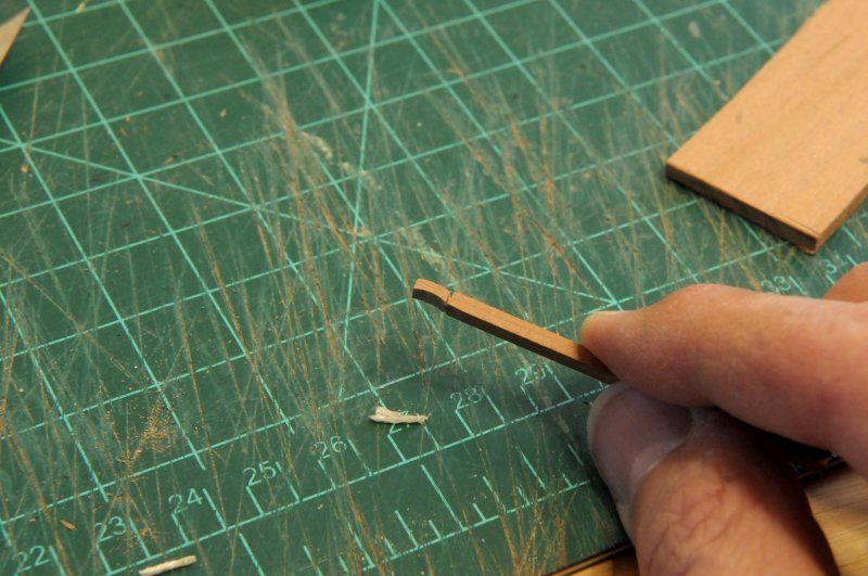
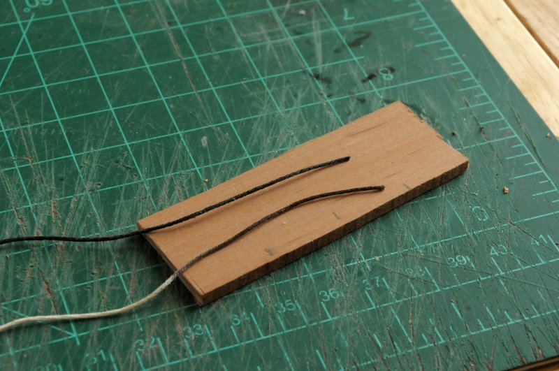
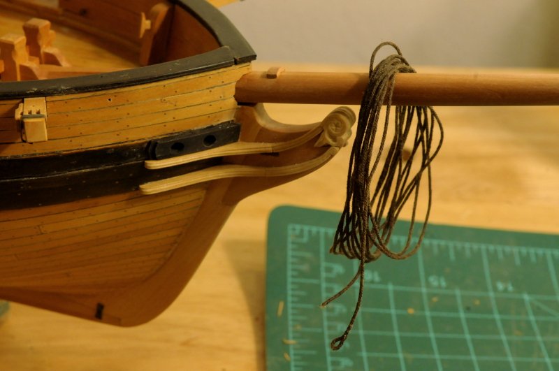
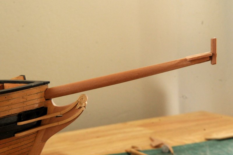
After looking at the bowsprit in place, I wasn't sure I had it at the right angle. The cap seemed tilted forward a bit. I pulled the bowsprit out and laid it against the Chapelle drawing, and the angle of the cap to the bowsprit was spot on, so it seemed the bowsprit needed to tilt up a little. That little chock I put down at the deck needed to move up to the top of the bowsprit tenon, and the bowsprit tenon/heel needed to sit right down on the deck. Here is the chock piece moved to just under the crosspiece-- And now test fit with the bowsprit-- You should be able to see a slight difference in the two following pictures. The first is before I changed the angle, the second, after-- Next I did a trial gammoning, just to get an idea of how to do it, and also to mark on the bowsprit where the cleat should go-- The cleat was then cut out. Following Glenn Greico's model of the brig Jefferson, there is only one wide cleat, on the top of the bowsprit-- The gammoning is of tarred rope, so I made a test, one piece stained black, and the other a dark brown. It's a little hard to see the difference here, but I like the brown better, it's not as stark, a little warmer-- So, gammoning cleat attached, rope ready with the eye splice in the end-- Ron
-
Anchor Question
rlb replied to rlb's topic in Discussion for a Ship's Deck Furniture, Guns, boats and other Fittings
Thanks for the video link Allan. That looks like something I could try. Ron -
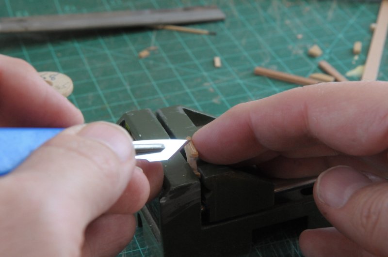
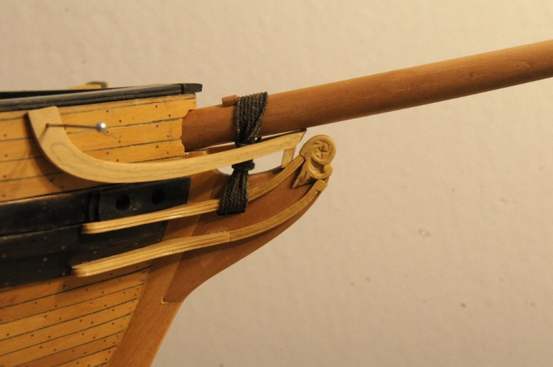
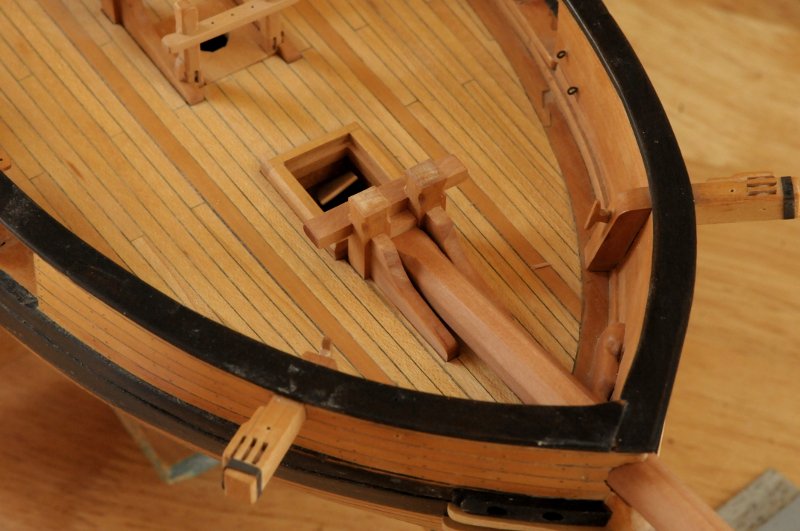
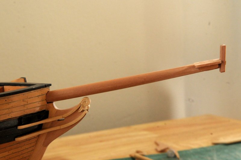
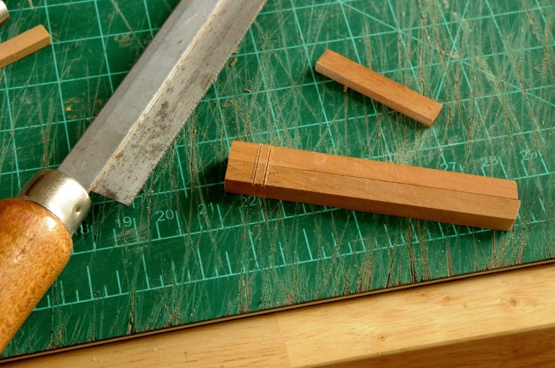
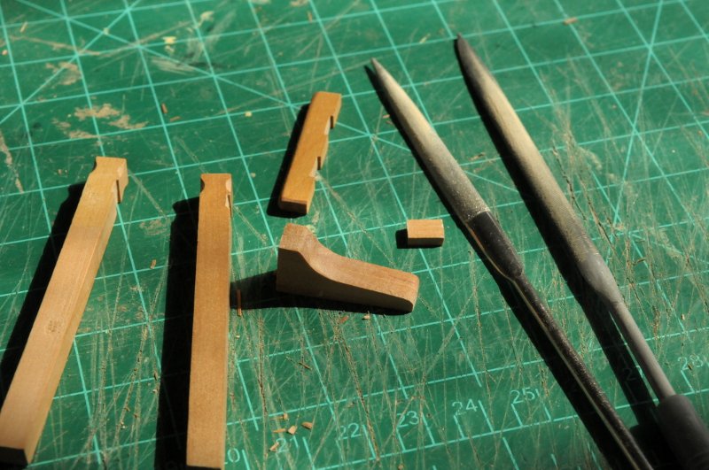
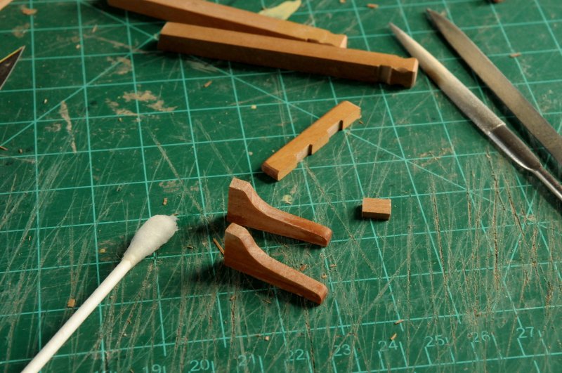
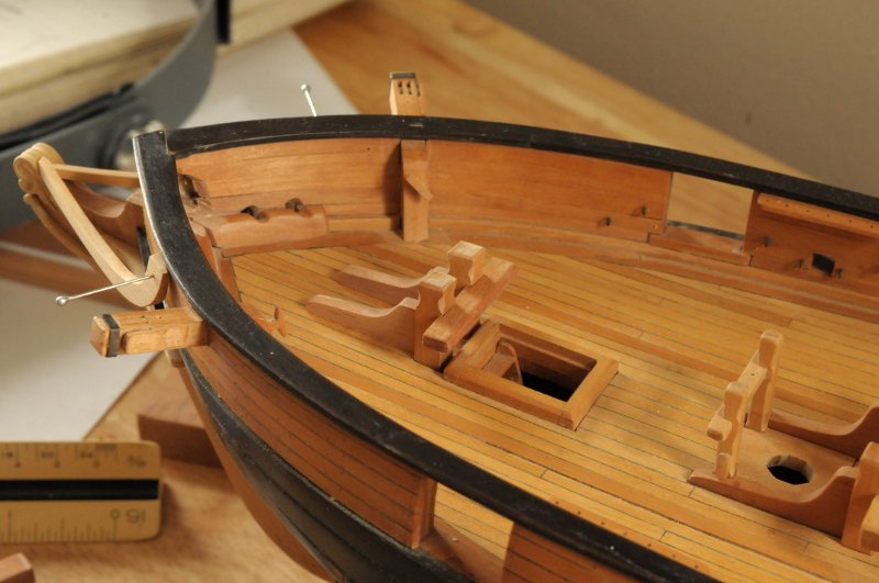
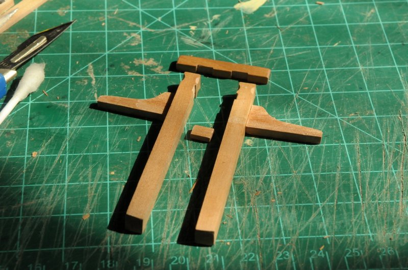
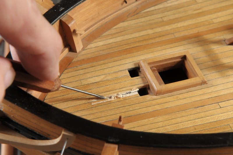
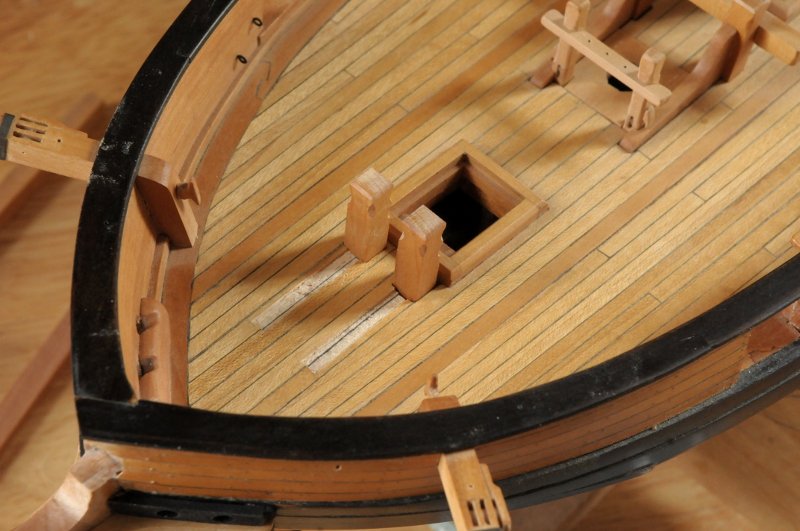
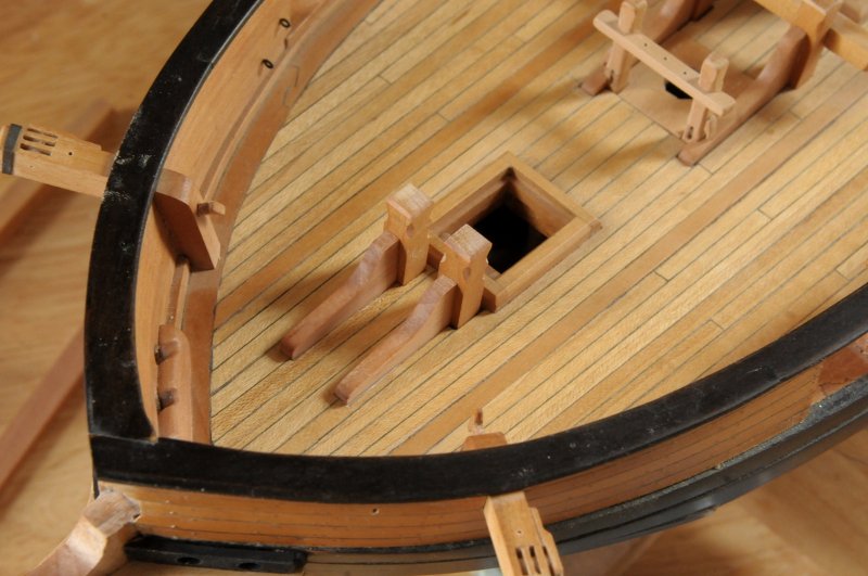
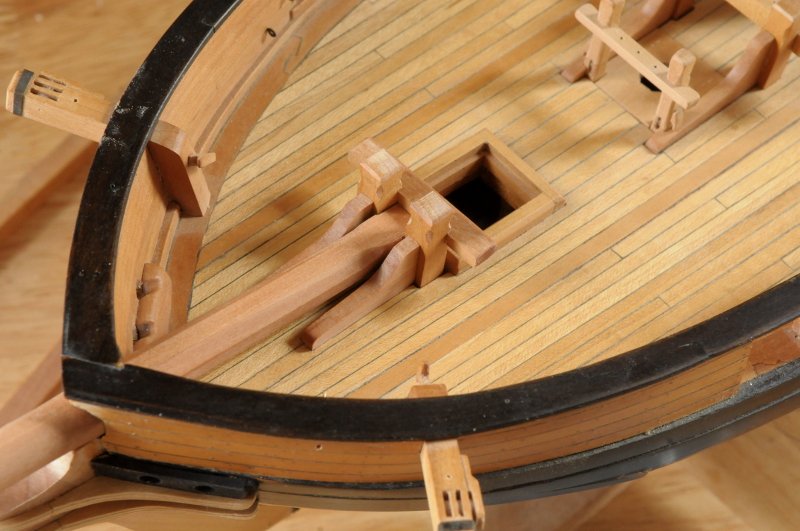
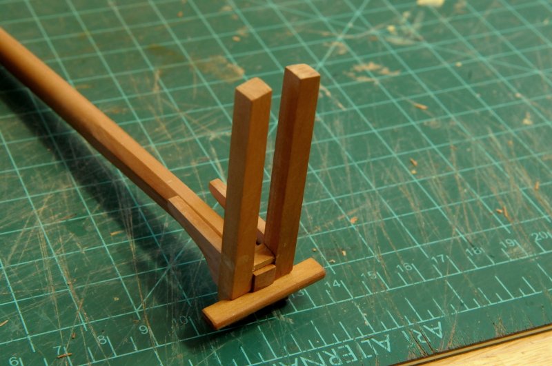
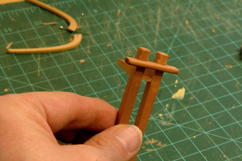
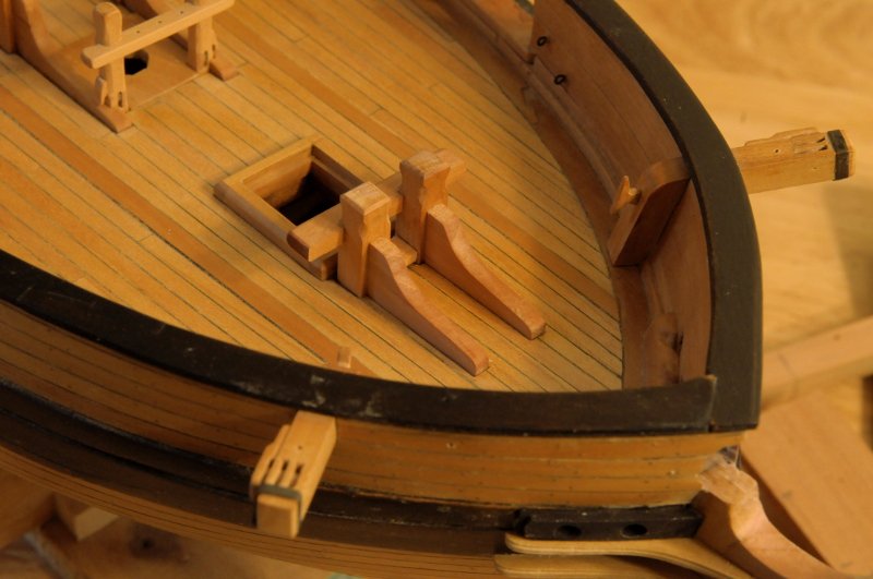
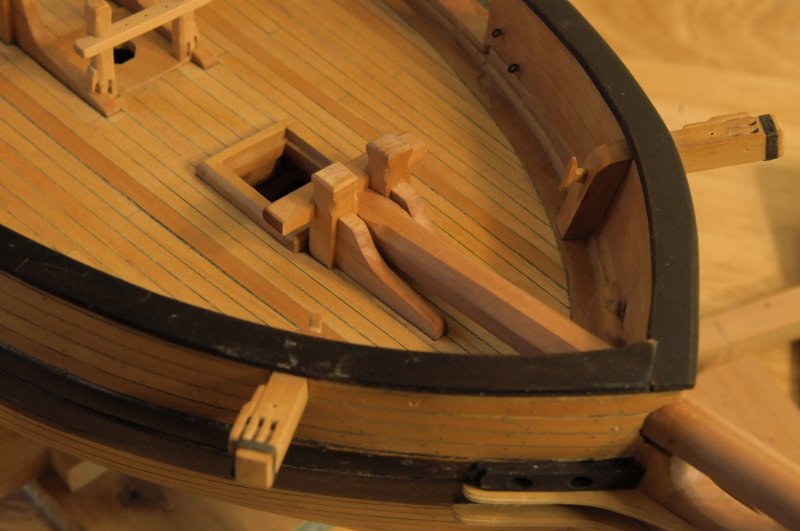
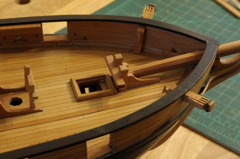
Work on the Bowsprit Bitts: I started the notches for the crosspiece with the saw-- The notches in both the uprights and the crosspiece were cut out with the saw, a knife, and files. The knees are temporarily glued together so they can be identically shaped, and the small piece you see next to the file will go underneath the bowsprit tenon, near the deck-- The shaped knees are easily separated with isopropyl alcohol-- Here are the pieces of the bowsprit bitts. You should be able to detect the slight upward angle of the knees because the deck is sloping up at the bow. Full disclosure, the uprights are probably a little oversized, and they should probably be tapered as they go below the deck, but I made them very early in the build, when I wasn't aware of such details, and I planked the deck around them. I do not have a problem letting this go as is-- Here are the uprights, knees and cross piece dry fit-- There is one problem, which in this case, I do not want to let go as is. If you look at the main bitts on the right in the above photo, you see the deck planking goes around them, and they correctly sit on the deck beams below. With the bowsprit bitts, at the time I planked the deck I didn't think enough about how they would be made, and I planked over the areas where the knees should be. This means surgery on the deck-- I will not carve this out all the way through to the deck beams. Just enough so it looks like the deck is planked around the knees. Here are the two shallow knee slots carved out-- And the knees dry fit-- Now the bowsprit added to get an idea of how it looks all together-- The bitts pieces were then glued together. They were glued while fit on the ship, so looked exactly like the last photo. Except for that little piece that goes underneath the bowsprit. The glued up bitts were taken off, and the little foot piece was glued on, using the bowsprit to space it correctly-- So here's the glued up assembly-- This slides neatly into place, still unglued to the ship itself for now-- And with the bowsprit added-- It's good it's not glued in yet. I realized looking at the photos that I had forgotten to very slightly round the edges of the knees, as was done on the main bitts knees. Ron
-
Anchor Question
rlb replied to rlb's topic in Discussion for a Ship's Deck Furniture, Guns, boats and other Fittings
Thanks Bob. Now I have a lot to think about! The wax/ceramic method sounds pretty involved (now I have to find a kiln, or someone to do the casting!), not sure I'm up to that. The brass sheet is definitely do-able, and I already have everything I need. -
Sam, it's a pleasure to have you drop in again. I think I have built up a big enough head of steam to keep me going longer than my last couple of bursts. I'm excited to be modeling again. Ron
-
Anchor Question
rlb replied to rlb's topic in Discussion for a Ship's Deck Furniture, Guns, boats and other Fittings
Thanks for the info B.E. The round-crown or -armed anchor does seem to have been adopted earlier by the other navies. I like the look of the angled crown anchors better! I'm continuing to research this question, with some concern about how many anchors I really want to build (2, 3, 4?), not to mention how to make them. Wood, painted or stained black? (That one is almost a non-starter for me.) Cut out of brass, soldered and blackened? Cast pewter and blackened? I'm leaning toward the last method. It would give me an opportunity to learn a new skill (though has a much higher cost as I have none of the equipment!), and I think it will be easier to make the mold originals out of wood and cast them, than to fabricate multiple brass anchors. I could also cheat and cast two alike for the 1500 lb and 1300 lb anchors. Better yet, I say the 1500 lb anchor is stowed below, and the 1300 lb and 1200 lb anchors are close enough to cast the same and show on the model. Hmm. I'm not sure my conscience will allow that. Ron -
Anchor Question
rlb replied to rlb's topic in Discussion for a Ship's Deck Furniture, Guns, boats and other Fittings
Thanks Bob. That might explain why (as Mark noted) you see models with both, and on one I know of it's a smaller anchor that has the folding iron stock. Being a smallish brig, the anchors called for aren't huge. Chapelle says Oneida had one each of 1,500 lbs, 1,300 lbs, 1,200 lbs, 800 lbs, 400 lbs, and 200 lbs. Maybe I will show the two largest as traditional angle-armed, wood stocked anchors, and show 1 or 2 of the smaller anchors as round-armed, iron-stocked; folded and stowed.
