
Supplies of the Ship Modeler's Handbook are running out. Get your copy NOW before they are gone! Click on photo to order.
×


rlb
-
Posts
655 -
Joined
-
Last visited
Content Type
Profiles
Forums
Gallery
Events
Everything posted by rlb
-
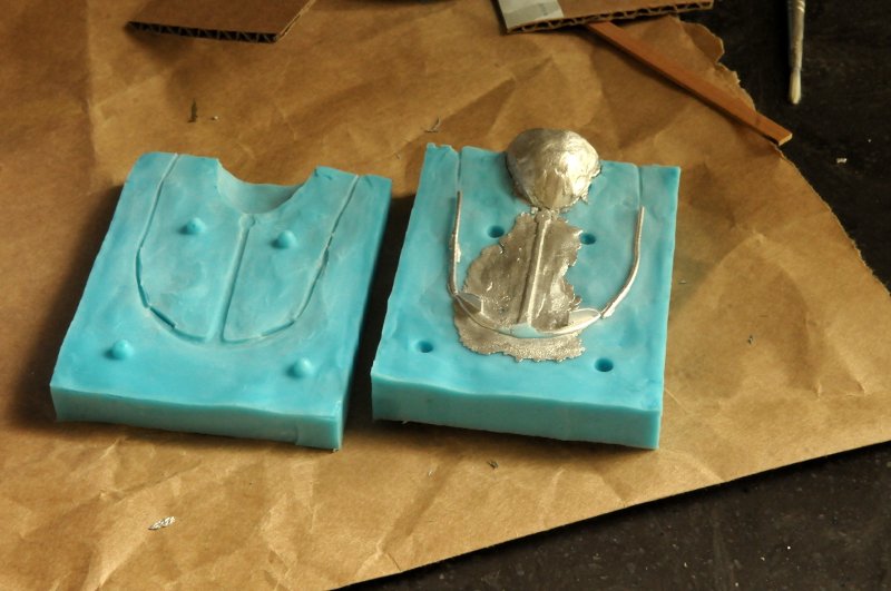
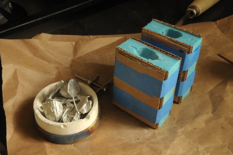
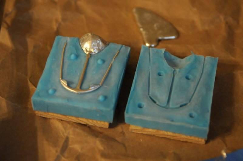
 Carrying on with the anchor molding and casting: The second RTV pour, completing the molds-- After separating, these were not quite as well done as my first mold. Mostly, I had to clean up some of the air vents, but there were some other irregularities as well-- Then I talcum powdered the molds and taped them up-- I heated up the metal (and heated the molds in the oven, before taking them out for this picture)-- When the metal was ready, I poured. At this point, the back end of beginner's luck reared it's ugly head-- On the third mold, the metal just ran completely through the mold!!-- Opening this third mold I was quite surprised to see there was nothing cast. The metal had all run through the mold-- The second mold also didn't look good. There was excessive "flash", indicating that the mold halves were not in close contact-- The third mold (first poured) seemed okay-- These two might be keepers, if I could trim the excess metal from the anchor on the right-- I couldn't. The anchor snapped in two while I was trying to trim the metal. Redo. So, I figured my cardboard and tape hadn't pressed the two halves of the mold together well enough (even though I had done the same as I had done on that first successful small anchor). I changed my tactic a bit, using two layers of cardboard, with the innermost matching the dimensions of the mold, and less tape holding the mold together-- These were poured-- And the results were much better-- Then, I re-poured the third mold from the first try which had seemed good. I just wondered if with my new method it might be even better-- It was about the same as before. But all-in-all I am done casting!-- These should clean up okay, I have a couple of spares, and I am very pleased to have learned a new skill (though far from mastered it!). Ron
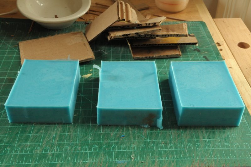
-
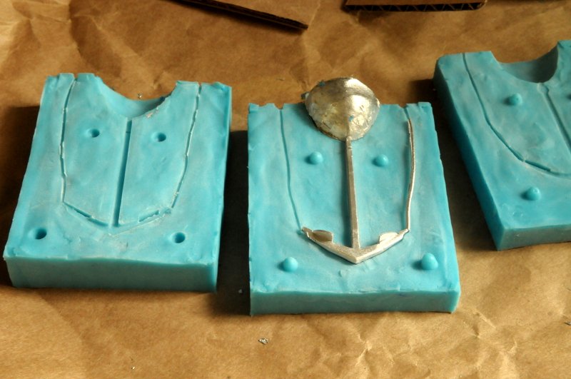
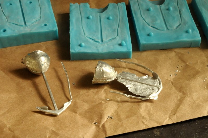
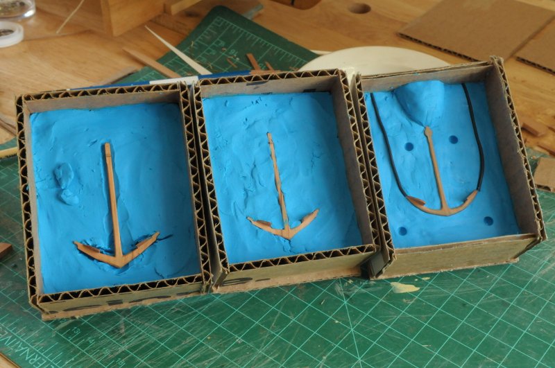
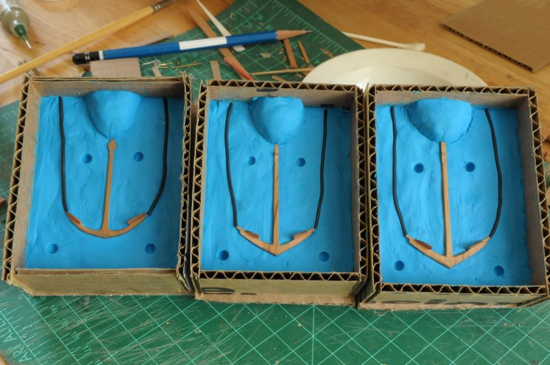
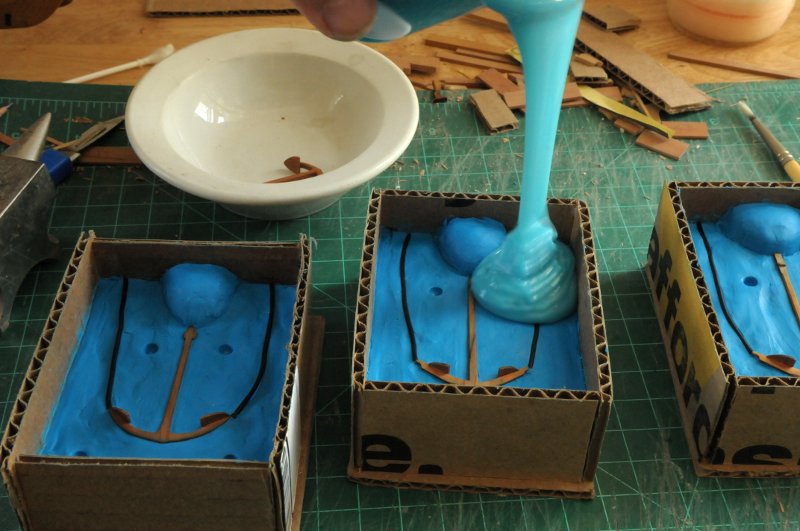
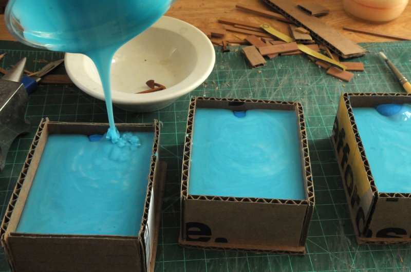
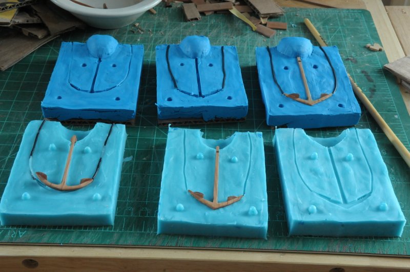
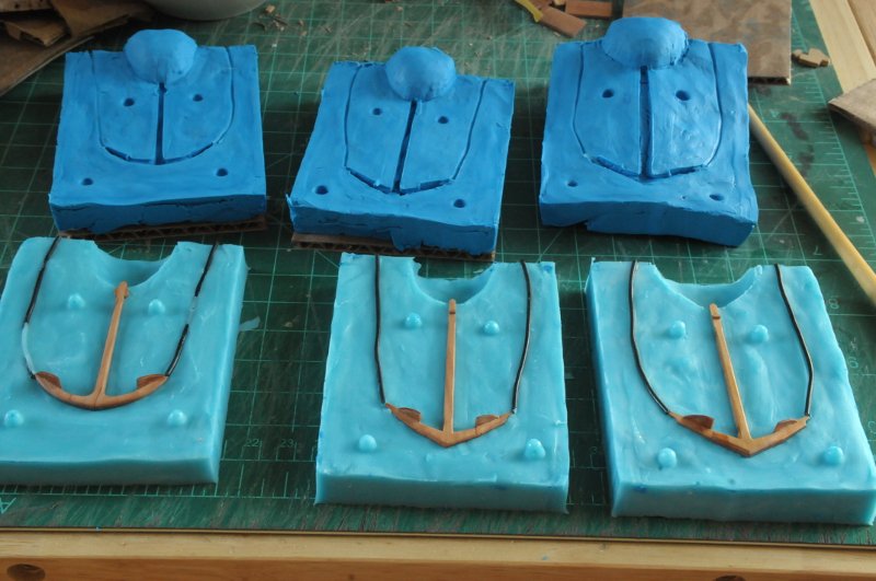
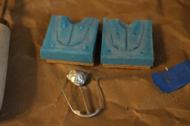
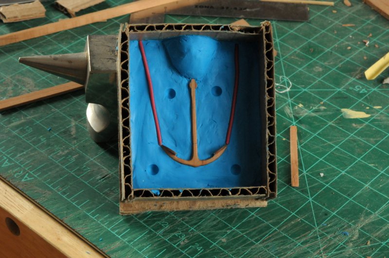
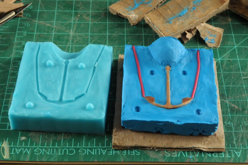
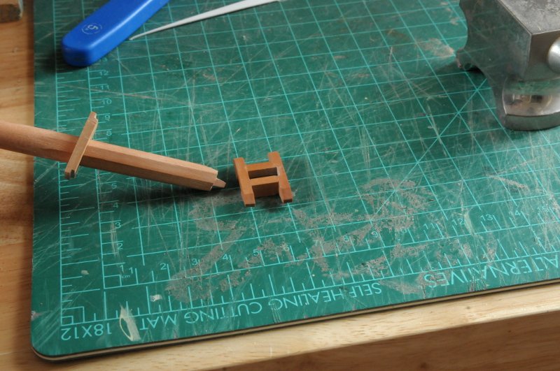
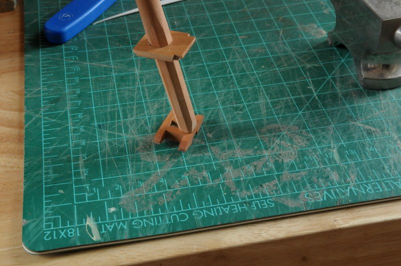
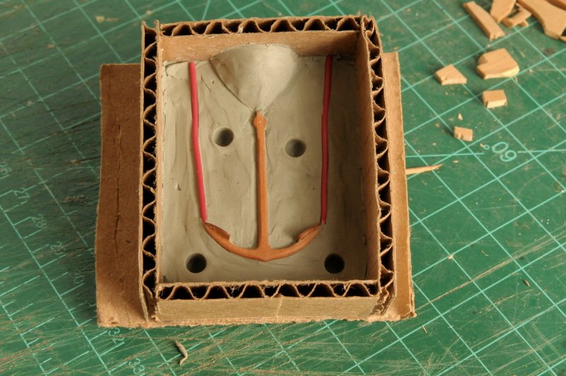
Part two of anchor casting. After successfully casting the first anchor, it is full steam ahead for the other three. This photo shows the three stages of working the clay around the wooden mold. First the clay base is roughly leveled and smoothed, and a cutout made for the anchor. Then clay bits are added and mushed up against the anchor form. Then the clay is carefully smoothed against the anchor form (with a small screwdriver, and the point of some tweezers), trying roughly to put the surface of the clay at the halfway depth of the anchor, and make sure it is "tight" to every profile of the anchor. It is important to avoid any stray bits of clay that may cling to the anchor form. Then wire air vents, the pour head, and the registration dimples are added-- After painting all the surfaces with mold release, these will be ready for the silicone pour- I find it difficult to guess the amount to mix up. Too much and it will go to waste--it is fairly expensive material, and I hate wasting anything anyway! Using the amount I used for the first anchor, adjusted for my slightly bigger box for these larger anchor molds, I mixed up a batch and started pouring-- As I got to the end, I realized I wasn't going to make it. The pour caps remained uncovered-- It's the quick setting (5 minute) variety, so hoping I wasn't too late, I hastily mixed up a small amount of additional silicone, poured, and it was just enough to cover-- Unboxing the molds. I had added two layers (one still sticking to the clay) of cardboard under the clay so I wouldn't need to use as much clay--without the spacers I wouldn't have had enough clay for all three molds-- Interesting that they peeled apart in three different versions. One with the anchor and vents with the silicone, one with the anchor but NOT the vents, and one with the anchor and vents sticking with the clay-- Doesn't matter, the parts stuck in the clay are positioned back in the silicone. I need to rebuild the boxes around these, fill in and add some more clay for the pour heads, and they will be ready for the second silicone pour-- Oh, I also made the twenty (plus some extra) toe link loops for the chain plates, and bent them into shape. In the picture they look very irregular. Some of the angle bends I can redo better, but the squiggle irregularities I'm not sure I can eliminate. They were a pain to make-- . Ron
-
Converting a Backyard Shed into a Model Workshop
rlb replied to Hank's topic in Modeling tools and Workshop Equipment
Those are all great subjects, and I look forward to seeing them develop! -
Chris, that is awful. Gives the phrase "the dog ate my homework" a whole new meaning! Take a day or two. Then the re-do will not seem as bad. You know it will be better in the end. Ron
-
Converting a Backyard Shed into a Model Workshop
rlb replied to Hank's topic in Modeling tools and Workshop Equipment
Well Hank, I have been watching your progress on the shed (I mean workshop). And that is all wonderful and good, but the real thing I want to know, is what you will build in it?! I am a great fan of your Peacock and New Jersey, and I can't wait to see what comes next. Ron -
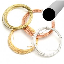
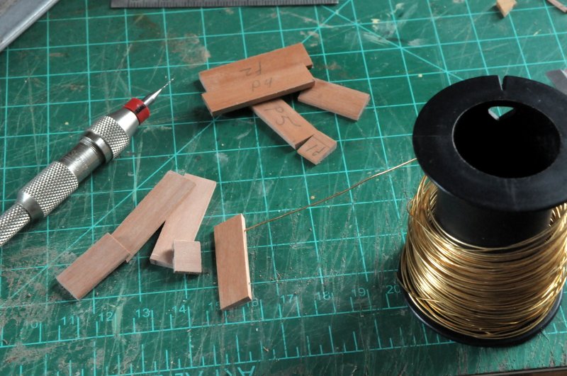
Thanks Hamilton! Martin, The last batch of wire I bought here: https://contenti.com/ Beadsmith German Round Bead Wire They have multiple gauges and types. I bought plain brass. It soldered just fine. It is half hard which is good in some ways, but not in others. It's definitely harder to form. Heated to solder, it becomes soft. I just noticed though, when grabbing this photo, that it is tarnish resistant. I wonder if that will cause a problem when I try to blacken it. (And maybe that's why soldering didn't discolor it?) Before I spend more time using it, I better try blackening! [Edited to say no problem blackening] They also sell soft, but in much larger quantities (therefore more cost) that I didn't need. Ron
-
Isn't there some ancient wisdom about how many words it takes to equal a picture? They are not really equal though, especially in ship modelling. To my everlasting shame and misfortune, if there are pictures, I have too often ignored the words, and regretted it. Ron
-
Ben This attention to the lay of the planking will pay off big time! Ron
- 399 replies
-
- 1
-

-
- winchelsea
- Syren Ship Model Company
- (and 1 more)
-
Bob, Sorry about your delamination woes. It's still going to be a great model. Not sure whether I paid more attention to your model or your amplifiers, though! Ron
-
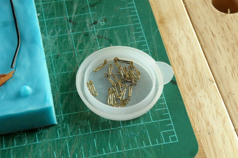
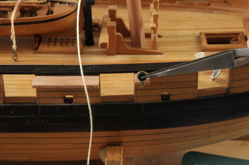
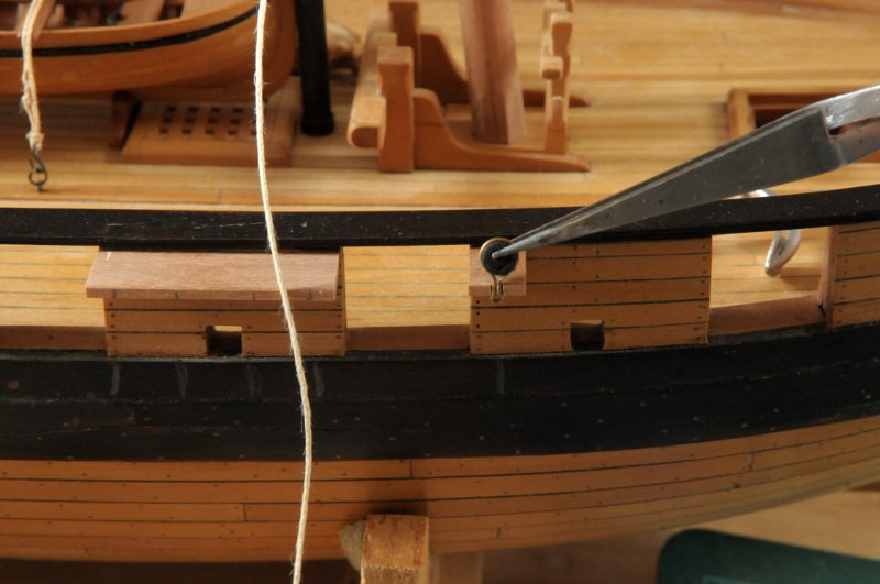
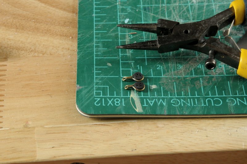
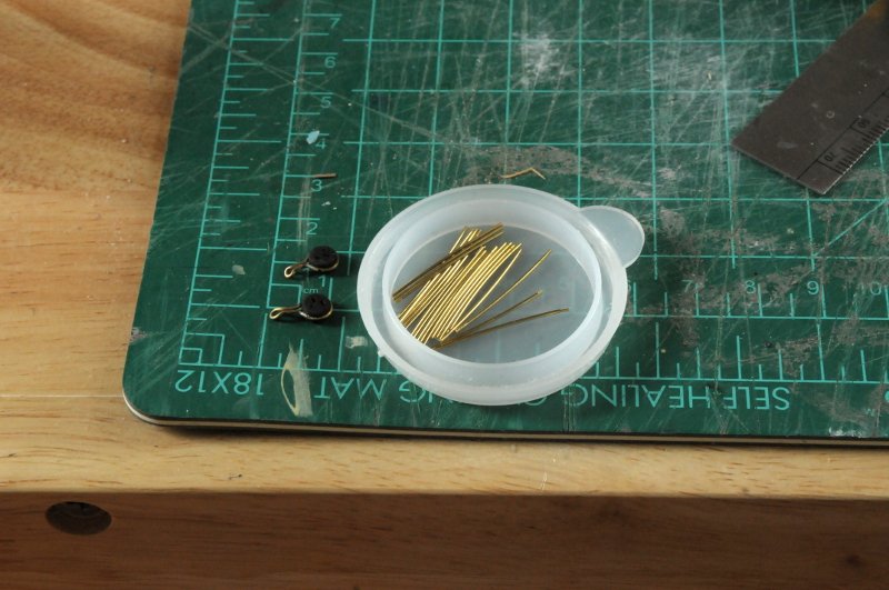
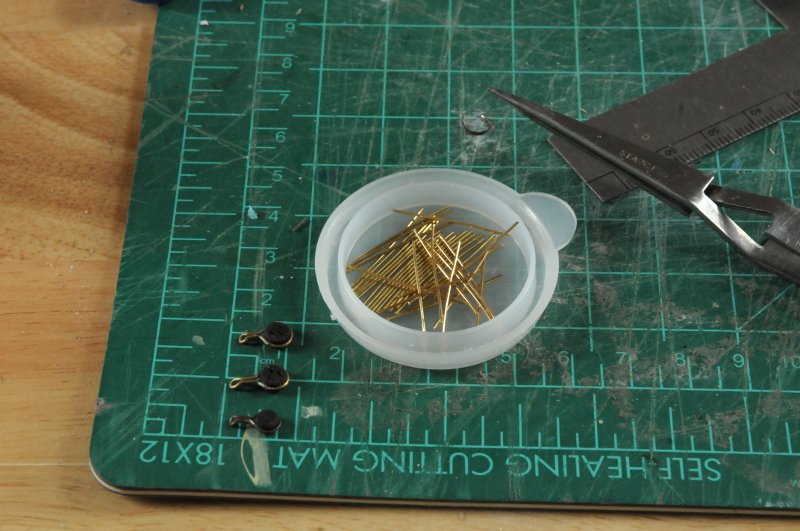
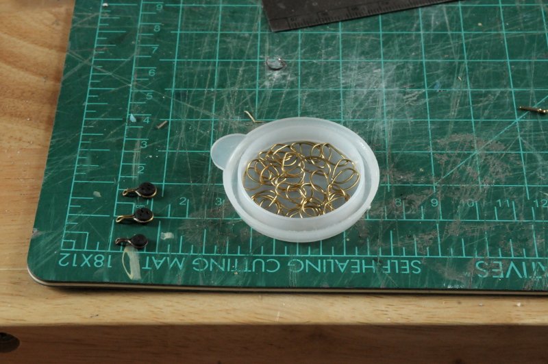
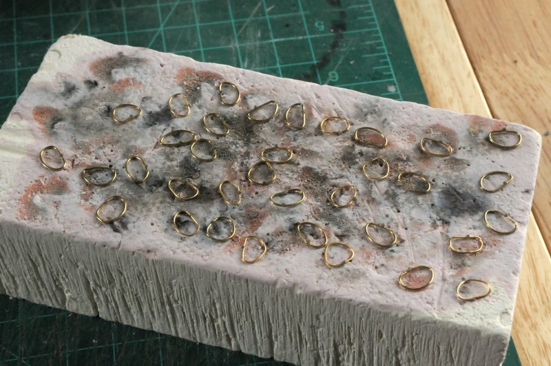
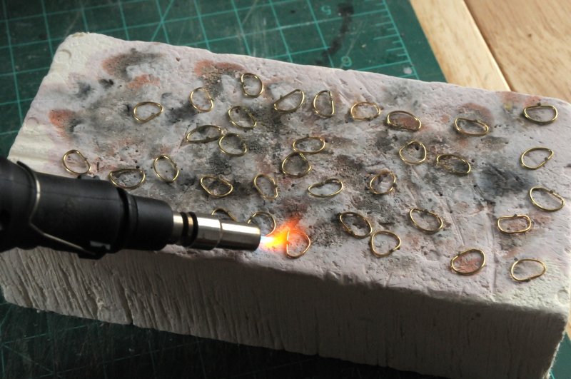
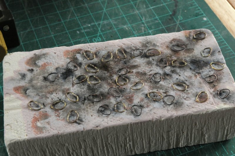
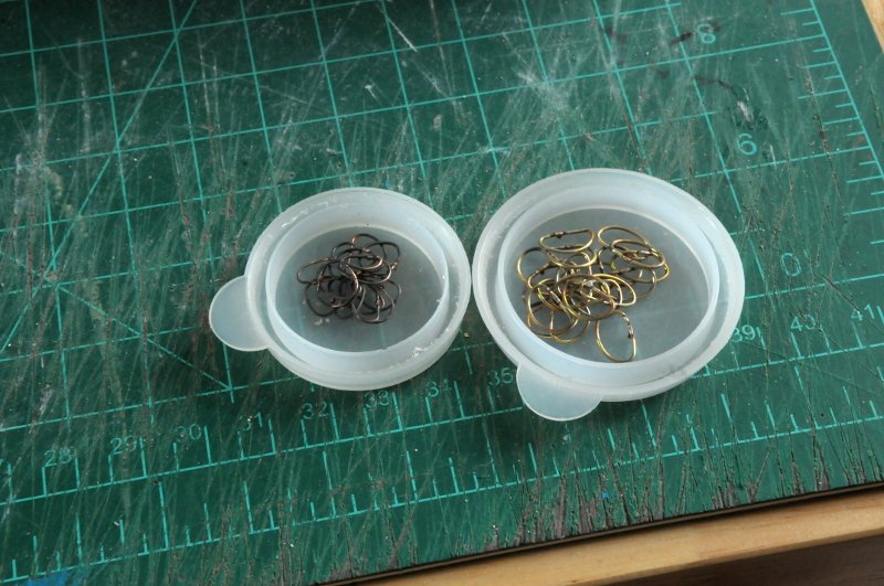
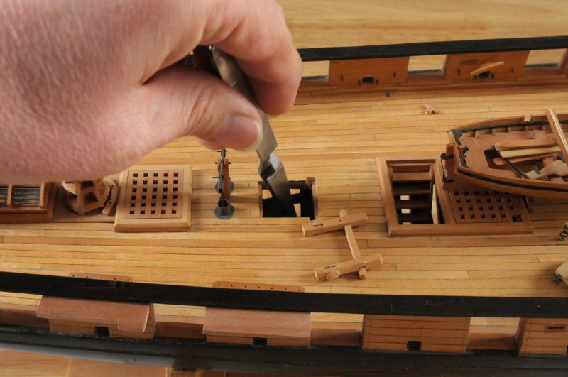
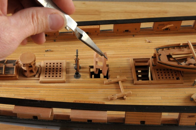
After the work and stress of the anchor casting, I needed a change, so I worked on the deadeye chain links. First I made a test link, soldered it and bent it around one of the deadeyes-- This was then test fitted to the channel, where it looks like it hangs a little too long-- A shorter link was made, and test fit-- This looks about right. Here is the comparison-- Twenty, plus an extra or two, were cut from wire stock- Another test was made for the smaller topmast deadeyes, and 12 plus some spares were added to the pile- These all needed to be bent into loops for silver soldering. Each loop needs to close without a gap, which means filing the cut ends flat, since the wire cutter made an angled cut. Also, there are two different sizes of wire for the two different sizes of deadeyes. I began to worry about how to tell them apart easily (measurement with the digital caliper is always a fallback though), as they collected in the container top-- I laid each out with a dab of silver solder paste on the joint. I haven't had a mass solder like this on the build!-- Surprisingly, the thinner wires darkened, while the others remained bright. They were two different sources of brass wire, the thinner one soft, and the thicker semi-hard-- The heat from the soldering now makes them all soft, but at least the difference in coloring made them easy to tell apart!- I'll have to repeat this a couple more times for the other chain links. And then I'll get back to the other anchors. Ron
-
Thanks, Tom, Joe, Ed, and Steve, and all who have looked, and liked. It seems there are never ending things to learn in this hobby, which is one of the things I love about it. Ed, the metal is a tin-bismuth alloy, that I bought from Micro-mark (I'm sure available elsewhere also). It is lead-free, and has a 280 degree Fahrenheit melting point.
-
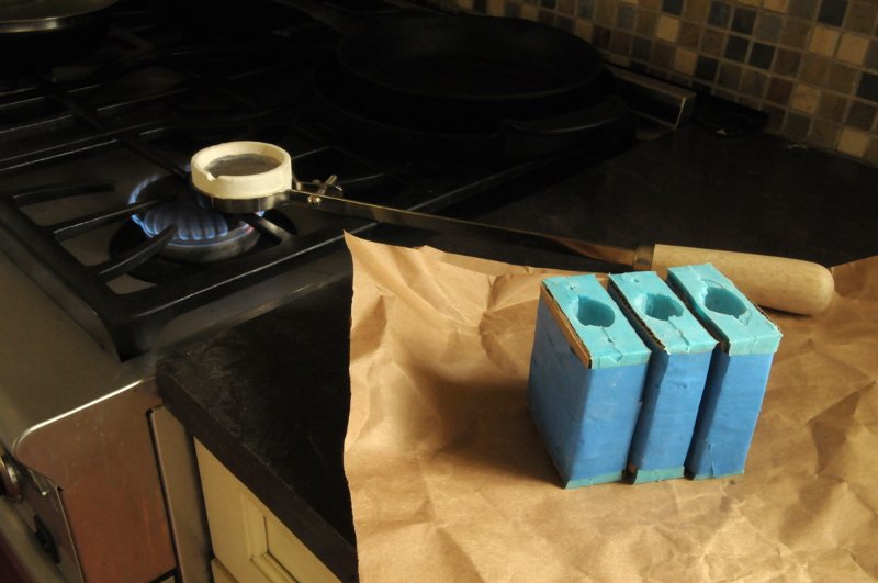
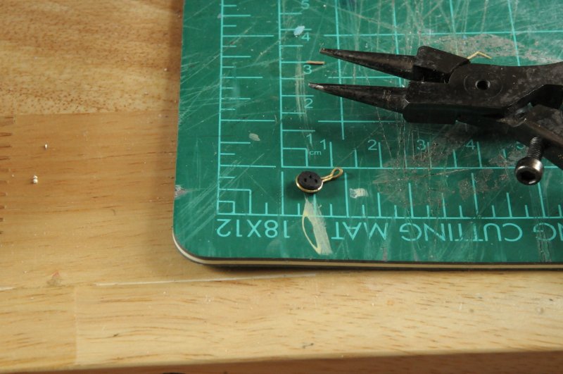
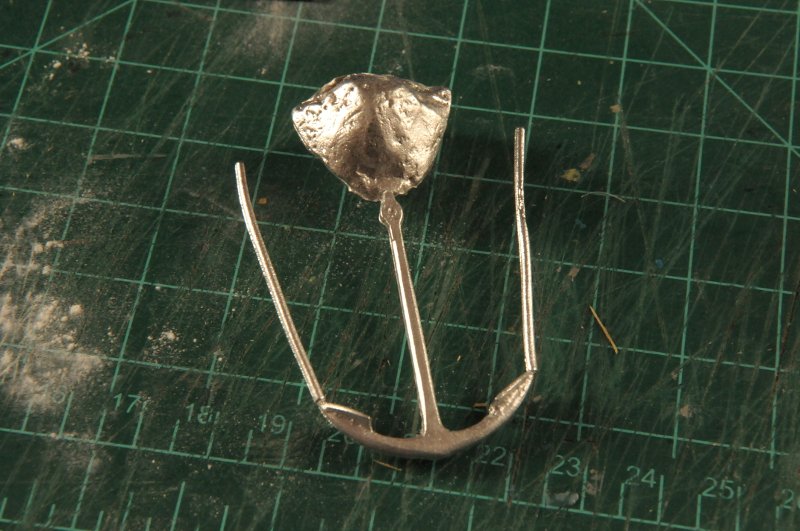
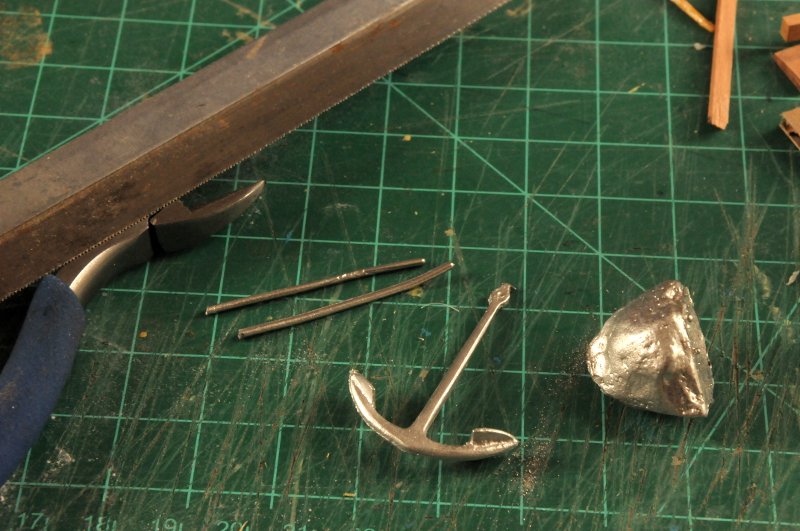
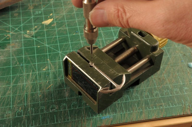
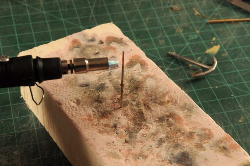
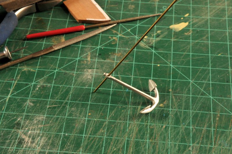
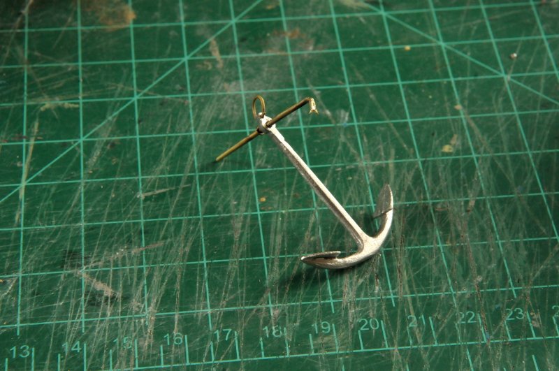
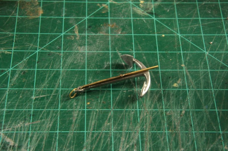
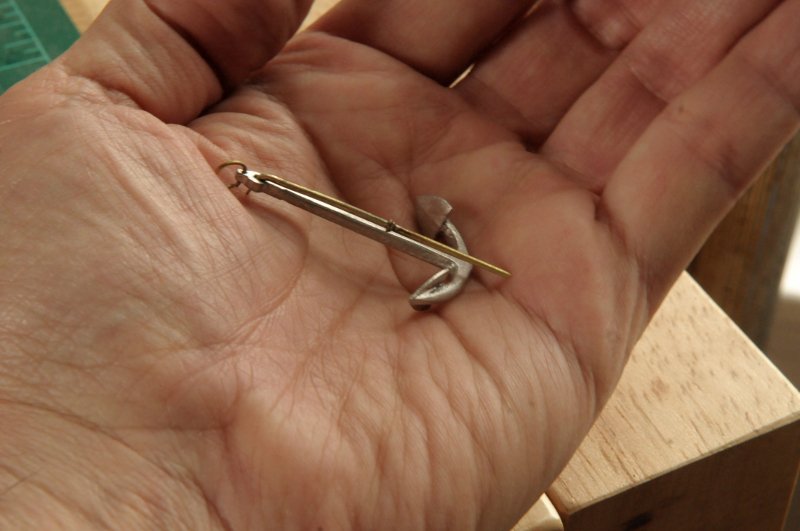
Thanks Dowmer, and captain_hook! As soon as I got my coffee this morning, I started setting up on the kitchen stove to cast the anchor. I heated the mold at 175 F degrees in the oven, while I waited for the metal to melt in the crucible on the stovetop. When it looked ready, I took the mold out of the oven, set it on the counter (with a sheet of shopping bag paper for protection) and poured--"Don't pour too slowly--be intentional!"--I was advised. As I practically dumped the metal in, it quickly spilled out over the top. No metal emerged from the two air holes though, so I was worried that the metal didn't fully fill the mold. I waited a while until the spilled metal was just warm to the touch, and then I opened the mold-- Sorry for the blurry images. I took these without a tripod, so depth of field was very shallow. But success!! It looks good-- Bringing it back upstairs to my workshop, I could give it a closer look-- I separated the air vents with wire cutters, and the pour head with a saw-- There was just a bit of a ridge where the two mold halves came together, but it looked like it would clean up fine. After doing that, I drilled the hole for the iron stock, and the ring-- I fit a piece of brass rod through the hole. This will need to be cut and tapered at both ends, and a ring soldered near the middle of the stock, to "stop" it in the shank-- After soldering the ring on (I used two rings of different wire diameter, thinking maybe I can file them to look like a single tapered ring), and tapering the brass with a file, I heated the rod to soften it where the stock needs to make a sharp bend-- Then I bent the stock, put it on the anchor, and made the forked end that Petrejus shows on his drawing. Well, my version isn't quite as elegant as his. But it makes the stock wider than the hole in the shank, so now the stock can't slide out in either direction. Now, there should be a slot in the stock opposite "stopper" ring, for a forelock, to lock the stock in position. I will omit that detail! I added the ring at the end of the shank, and this anchor is basically done-- The advantage of the iron stock is that the anchor can be stowed more compactly-- And for scale-- This is the smallest of the four anchors. I figured if I can get this one cast successfully, I should be able to do the others. I'll make all three of the remaining molds, and cast them all at once. Then blacken them all, together with the chain plate links. Ron
-
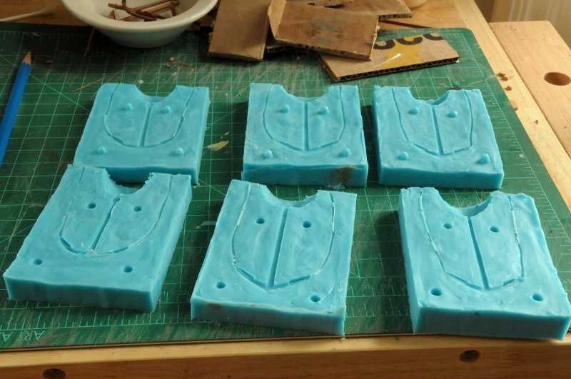
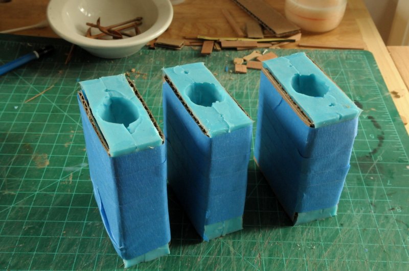
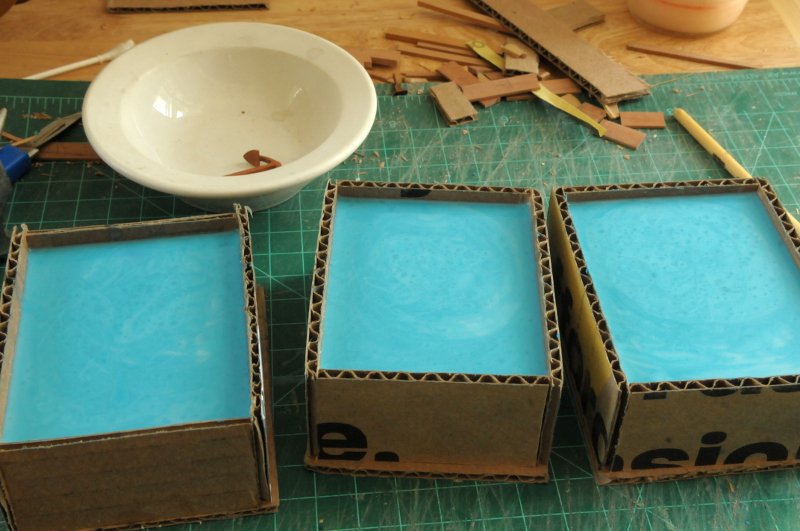
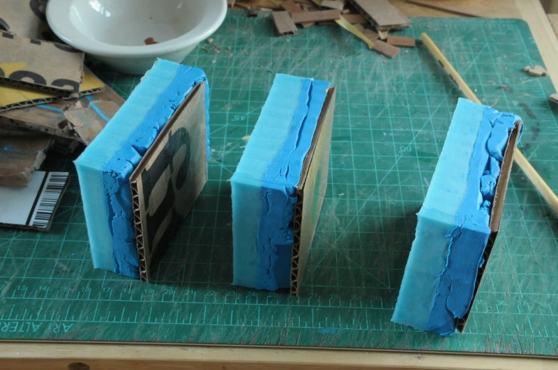
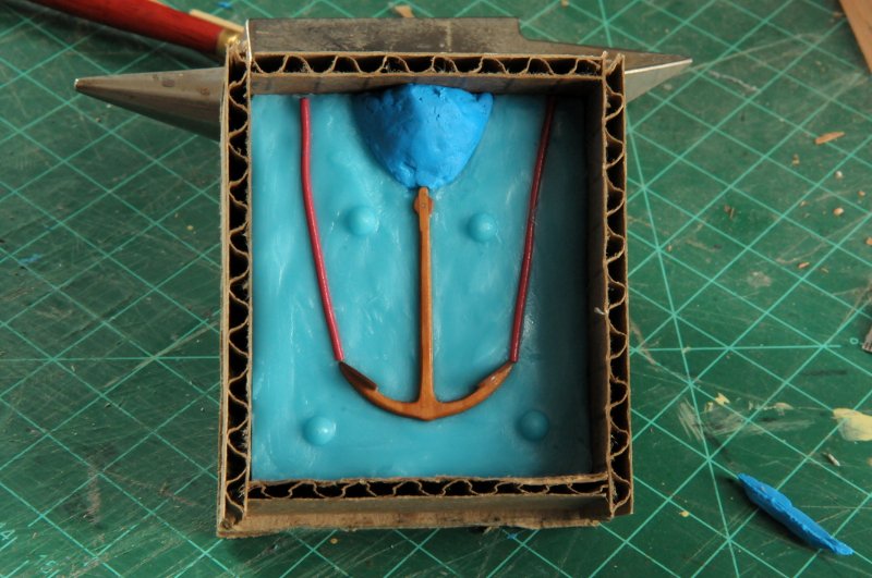
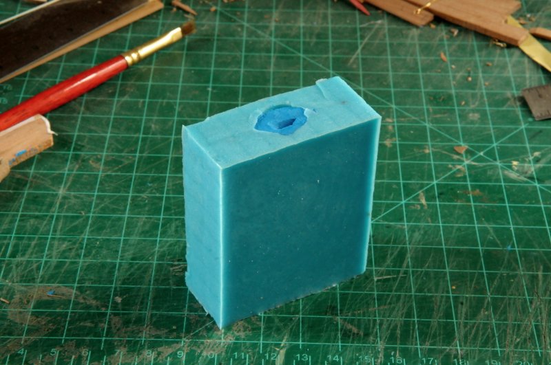
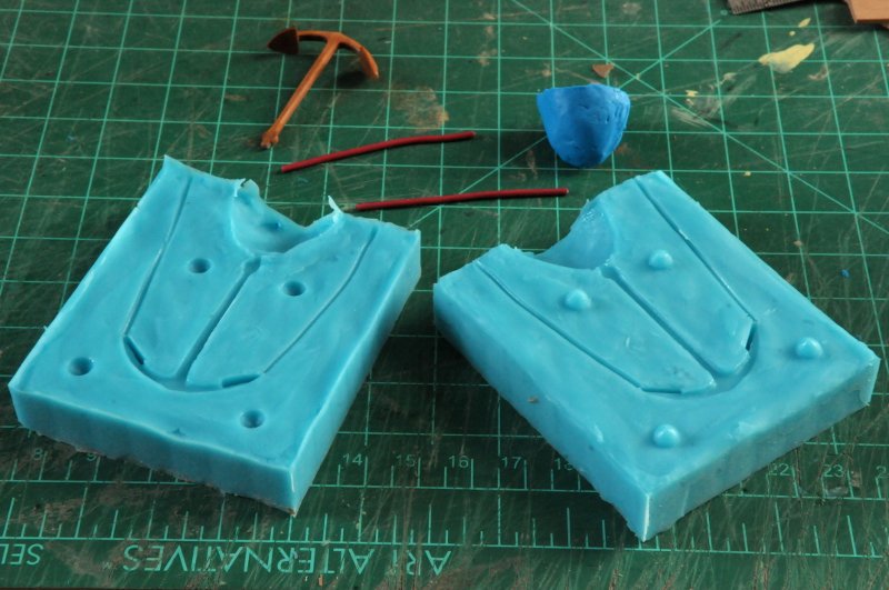
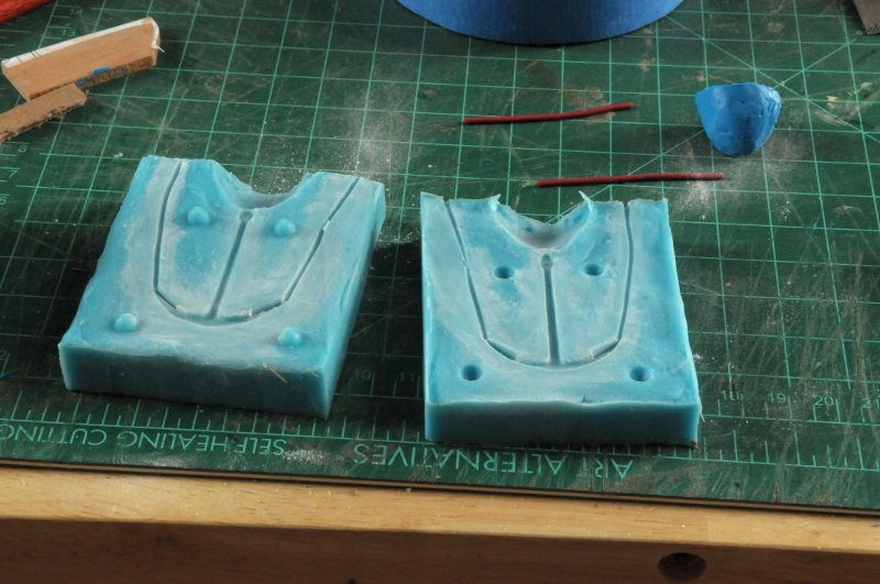
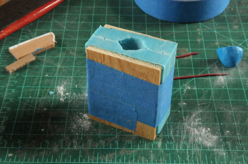
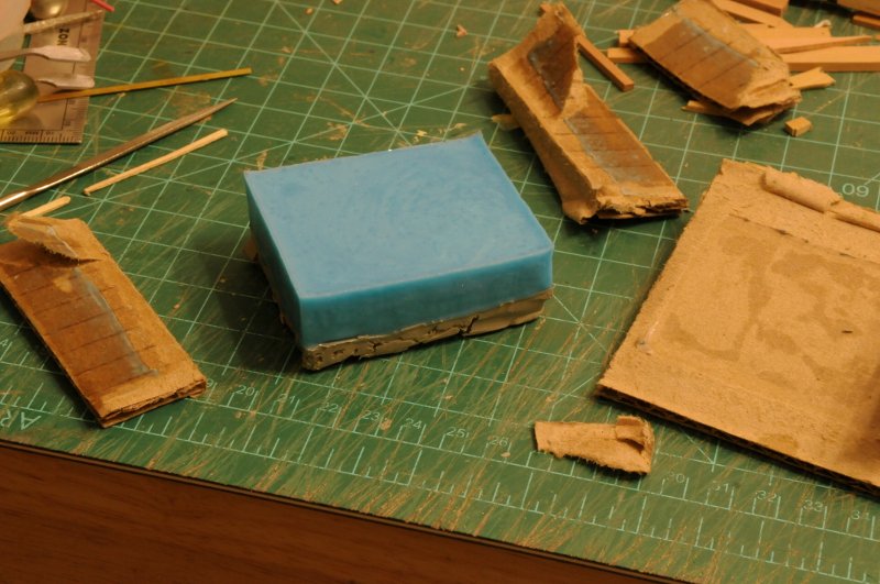
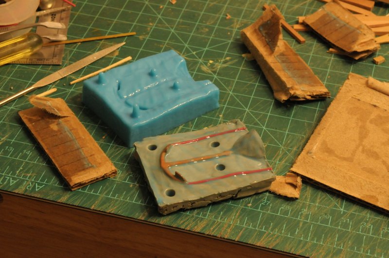
During the past week I received my Sulphur-free clay, so I was ready to try again with my anchor casting mold. As before, I made a cardboard box, formed the clay around the anchor, placed wire vents and formed a clay pour head-- Painted the mold release liquid over all the interior surfaces, mixed and poured the silicone mold material over it-- And when I peeled away the cardboard, it seemed I had a good first half of the mold. At least better than my goopy first attempt!-- After building another box around the silicone half, placing the anchor and wire molds, another clay head cone, and another painting of the mold release liquid, I was ready for the second silicone pour-- And after peeling away the second cardboard box, I had this-- Which separated into the two halves of the mold, which I can only hope are okay-- I did some minor surgery with a knife on the silicone at the air vent location on the palm tips, to make sure there was airflow (tested by blowing into the central cone with the halves held together--I could feel air on my cheeks from the two vent lines), I talcum powdered the mold-- And taped it together (I can't find any rubber bands, which the directions show-I will have to buy some)-- It's ready for the metal pour, which will have to wait until tomorrow. I've had my pre-dinner cocktail, and I'm done with serious work for today. Ron
-
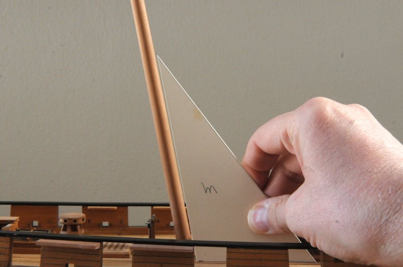
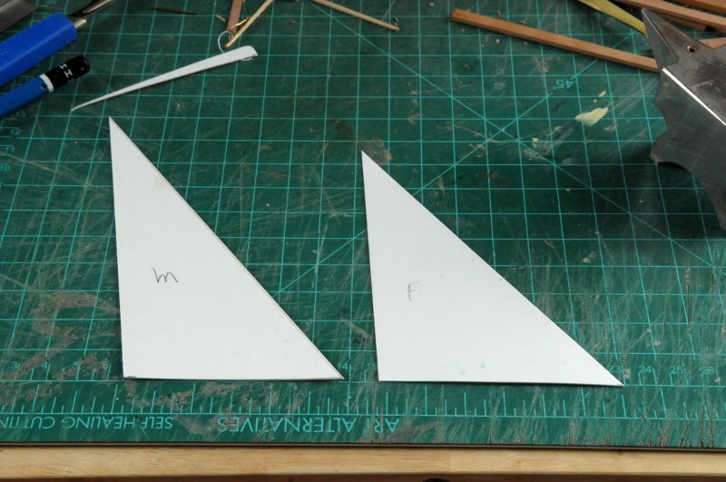
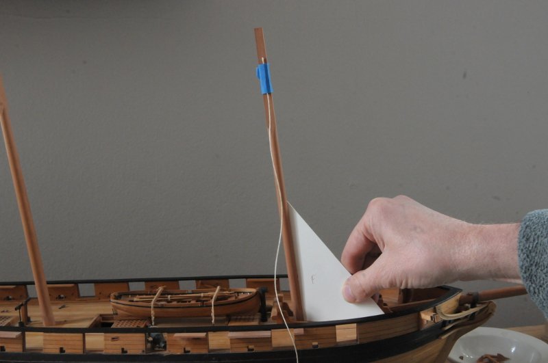
Thanks Ed! Martin, your worry made me double check my method. I checked the masts again. I think it works as long as the template is absolutely vertical and parallel with the mast, and your eye is perpendicular. You can shift your view angle to left or right, and the alignment angle remains constant. Ron
-
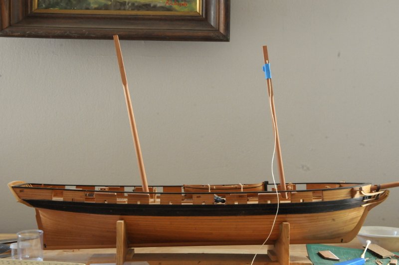
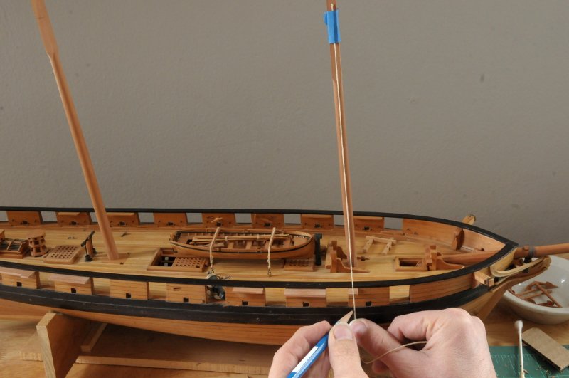
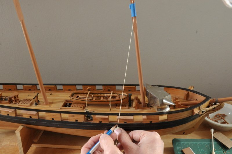
I was able to file the main mast partner piece to allow a greater rake, however, the mast step did not allow the heel tenon to slide forward enough. Happy that I hadn't glued it in place, I was able to retrieve the mast step from inside the hull-- And I extended the tenon slot forward. I also had to shorten the dimension of the mast tenon to allow even more forward play-- There is a deck stanchion that the mast step butts up against, which constrained the mast step, and even the heel of the mast. You can see where I also had to file a bit of the heel flat, so it didn't project forward of the edge of the mast step-- This done, I could reinsert the step (where I think it will remain unglued)-- And check the rake. Pretty close-- I used a different technique to sight the rake against the template, in which I put the template parallel to the mast but a bit offset. This way I had room on the deck to put the bottom edge flat. I think this is more accurate than what I was doing before in trying to hold the template right on the mast, and then having to angle the template around obstructions, or on top of deck hatches. I rechecked the fore mast using this technique and found I had to increase the rake a little bit. Fortunately there was enough play in the mast step to easily allow the adjustment-- Ron
-
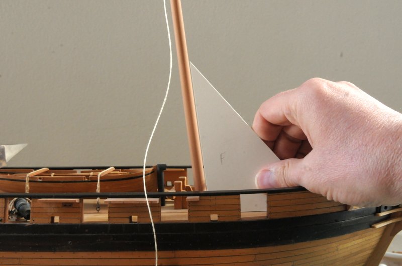
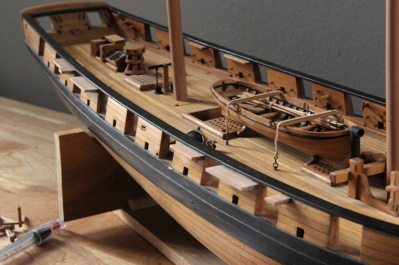
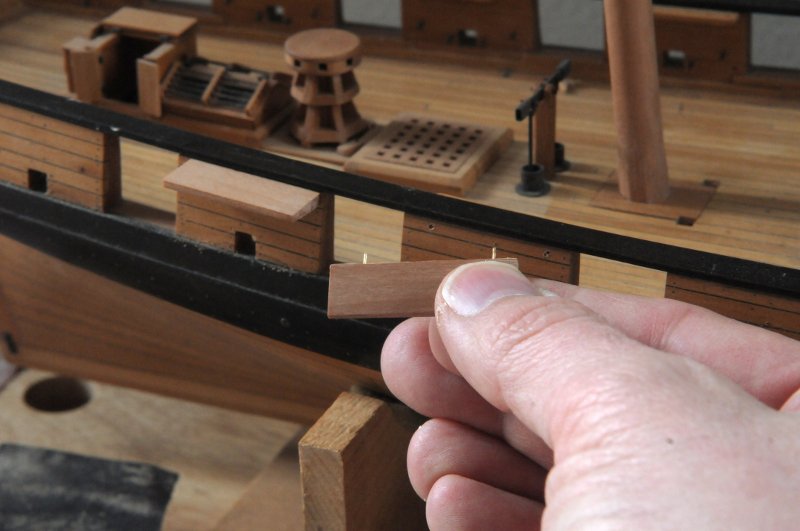
After cutting new channels to accommodate the topgallant backstays, here they are test fit to the hull. On the foremast, the last channel, which accommodates the topmast backstays and topgallant backstays, is narrower. I saw this detail on Glenn Greico's Jefferson model. I was less sure what to do on the second channel for the mainmast, which has a foremast shroud, the topmast backstays, and the topgallant backstays. In the end, I decided to notch it back, rather than taper it, reasoning that that way, the chainplate links for the topmast backstay deadeyes would be more consistent, and the deadeyes themselves would be straight in a row, parallel to the rail. Perhaps a wrong guess there, but Glenn's photos didn't show a similar situation! Here they are test fit-- Next I made card templates to set the mast rake angles. The bottom edge goes on deck, or at least parallel to it if there are hatches in the way. The left edge is the rake of the mast-- My foremast was right on, so I attached a string at the height of the platform-- Then I marked the location and angle of the preventer plates on the wale-- When I got to the narrower channel with the topmast deadeyes, I realized I couldn't mark the chainplate links. Those angles need to come from the crosstrees of the topmast! So more mast building needs to happen, or at least something rigged up to the correct location to run a string. I then checked the rake of the mainmast, and was surprised to see how far off it was. I double checked the template, because it seems like a big difference-- I'll need to work on the mast partner piece, as it's a snug fit to the present angle of the mast with not that much play. I may be able to file it to work, if not I'll need a new one of those. Ron

-
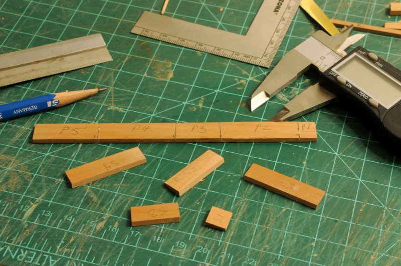
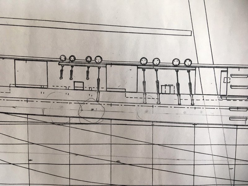
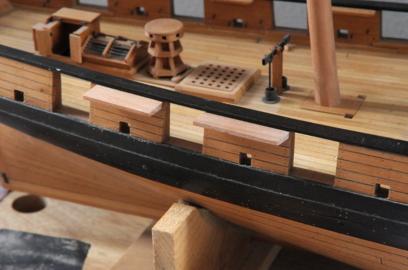
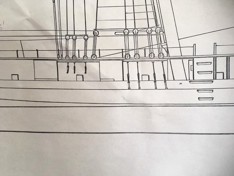
After my mishap with the anchor casting mold, work continues on the channels. I ordered some casting mold clay from Micro-mark on Apr 11th, but the order has not been filled yet, so I assume the coronavirus restrictions have that on hold. I measured the various channel pieces needed, and cut them out-- Holes drilled and wire inserted to make pins for temporary and permanent holding-- Holes were marked and drilled on the hull-- And the channels temporarily installed for marking the deadeye chainplates-- The second (aft) piece ended up a little too far aft, so it needs to be repositioned a bit. At this point I became aware of a discrepancy between Chapelle's hull and sail plans. I had been making my channels as shown on his hull plan, which is better drawn and more detailed. For some unknown reason I took a look at the sail plan. Here is a closeup of the hull plan, showing the mainmast channels (ignore the pencil circles from when I was working out the locations of the deck scuppers)-- He shows the main shroud deadeyes, and the topmast backstay deadeyes, but something is missing, that I might have noticed had I rigged a ship before. Here is the same view of the sail plan-- He locates the topgallant backstays on longer channels. Same thing with the foremast. So these two sections of channel (four counting the port side) that I have cut need to be remade. (I just noticed on this drawing he omitted a main shroud set of chainplate links!) Ron
-
Romulus, I think it is looking great! Your first planking is excellent. I'm not sure, but something doesn't look right with either the first pieces at the stem, or bulkhead #2. Before you do any more planks, study how the upper planks, near the top, will lay. You may have to so some adjustments in that area for the planking to lay well. Ron
-
I see what you mean. If it were a pattern with some width, like a cannon, I could see that working, but the target here for cutting the rubber in half is about 1/32nd of an inch, and I've got the interior curve of the arms of the flutes to cut into also. The anchor is only 1/16th (maybe slightly more) of an inch thick. I do appreciate your thoughts on the matter. Ron
-
Thanks for the advice, Dowmer. I've seen the option of suspending the pattern, and filling up to it with RTV, thereby bypassing the clay step. The difficulty there is making sure the pattern is exactly flat and level, and that the RTV pour is exactly halfway up the pattern, which seems difficult given the thinness of the anchor. I'm not sure I can do that. But I'll either give it a try while waiting for the new clay (already ordered), or if I still have trouble with the clay. Ron
-
Okay, here is the first unboxing-- Fail!! The rubber at the clay surface (though also around the wood and wire) was goopy and unhardened. My suspicion is that the clay I used was the cause. So, I will send away for the special casting clay. Ron
-
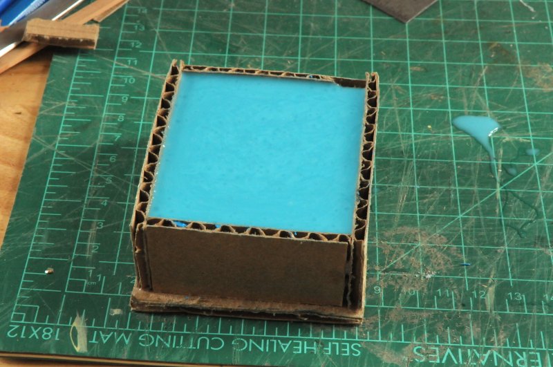
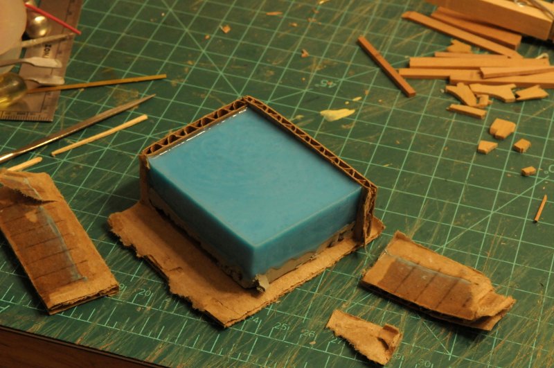
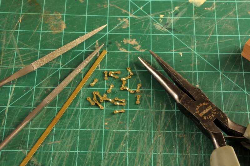
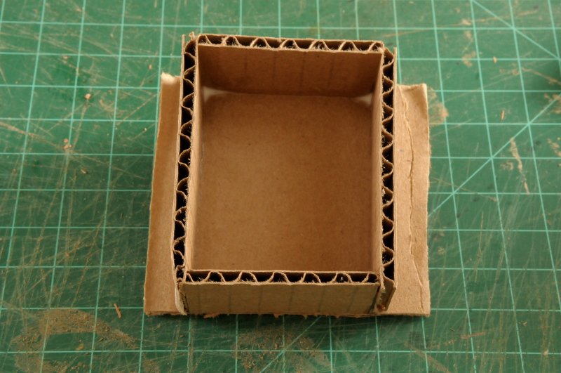
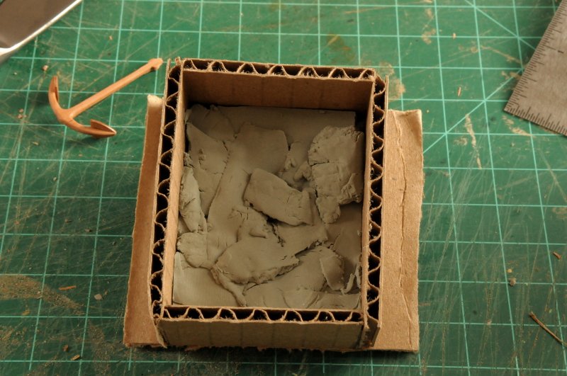
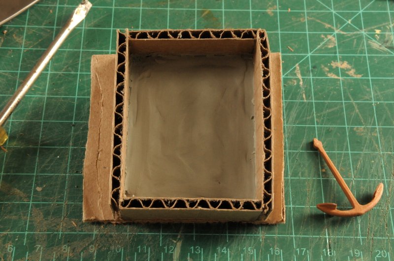
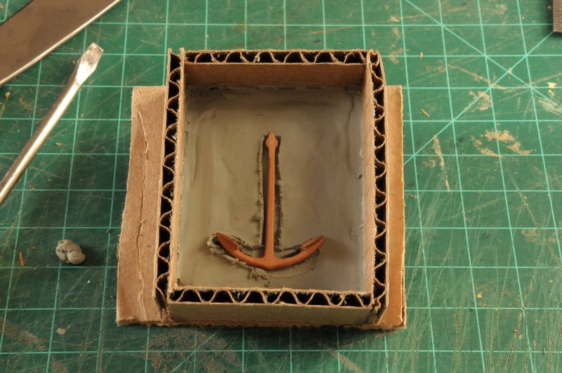
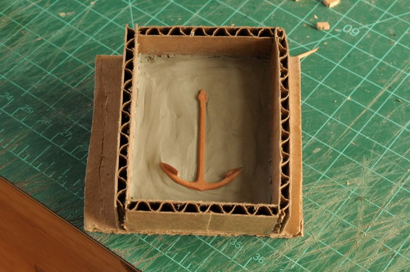
Thank you to all the "likers"! Here I have nearly completed the 20 Preventer Chainplate Links. Though much of the filing took place while they were still attached to each other on the strip of brass, I still had to finish them individually and my fingers are sore from holding these while filing. I think I will be drilling the holes larger, as the brass nails that I was planning on using don't fit. I was able to score a line down the middle of each before making the bend (you can see it on some of the right side up pieces), denoting the fact that in reality these were actually loops made of bar stock. They are not deep scores, and I wonder if they will even be visible when blackened. These will be stored away until all the chainplate loops are made and ready for blackening-- And now the anchor casting adventure begins. I am showing this as I go--so the failures and mistakes you will see. And I have a strong feeling that there will be plenty. First, nowhere did I see corrugated cardboard recommended as a box material. I know I have some illustration board around somewhere, but I have so many Amazon boxes!-- And the clay I have is not the special kind that Micro-mark sells. I forget to get that when I ordered the casting materials. So I am going to try regular modeling clay-- I put chunks in, and smoothed it out-- Then, because the clay is rather hard, and I was afraid I would break the palms off if I pushed it into the clay, I cut a depression for the anchor, so there would be less pushing-- Even so, I broke a palm, and had to re-glue it and wait. (I finished the preventer links during this interval.) After the glue set, I reinserted the anchor, and smoothed the clay around it-- Then, using electrical wire which seemed about the right diameter--though with my luck the plastic insulation will be incompatible with something, I made the air vents, and I made the register pockets with the end of a paintbrush. I formed a pouring head out of clay (there's an obvious issue with that, which I now realize)-- I painted on the mold release (which had the disconcerting effect of dissolving the clay a bit--maybe a hint of disaster), mixed up the rubber and poured-- So we will see together what becomes of this. Ron
-
Hi Romique, Excellent progress! It looks like you are taking your time and being careful. That is good. You mentioned "first layer of planking", so this will be double planked? I ask to make sure, because on your second layer of planking I think you will want to make sure your garboard strake doesn't curve up so far at the bow. It will cause crowding for the rest of the planks there. If this is a first layer, no worries. Ron