HOLIDAY DONATION DRIVE - SUPPORT MSW - DO YOUR PART TO KEEP THIS GREAT FORUM GOING! (Only 51 donations so far out of 49,000 members - C'mon guys!)
×


rlb
-
Posts
655 -
Joined
-
Last visited
Content Type
Profiles
Forums
Gallery
Events
Everything posted by rlb
-
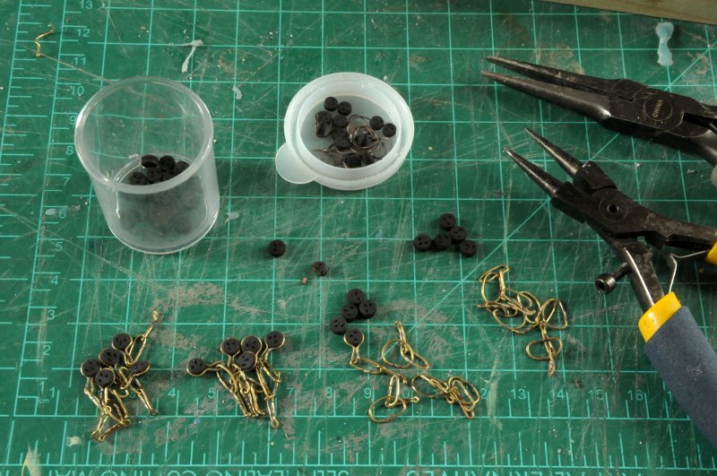
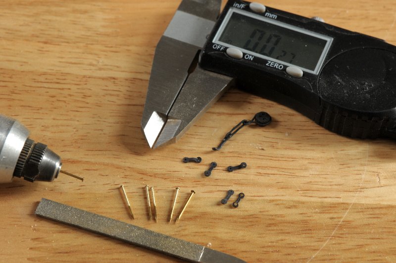
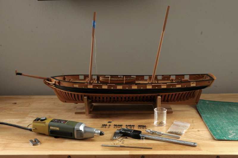
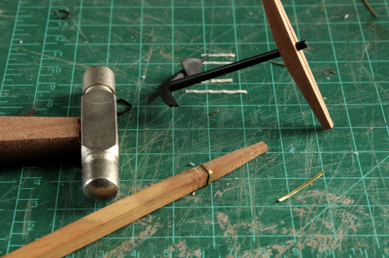
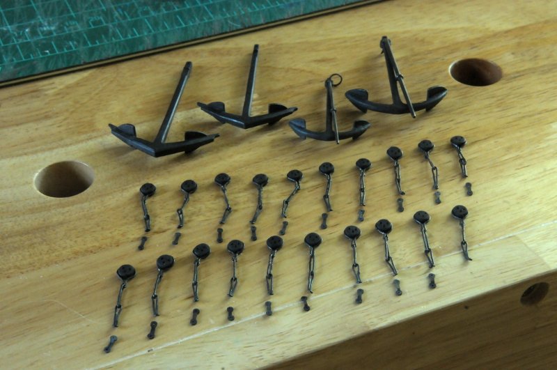
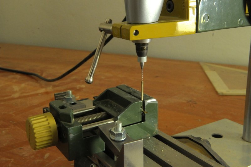
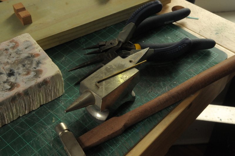
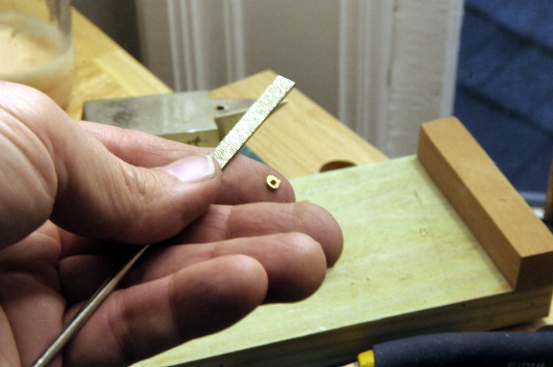
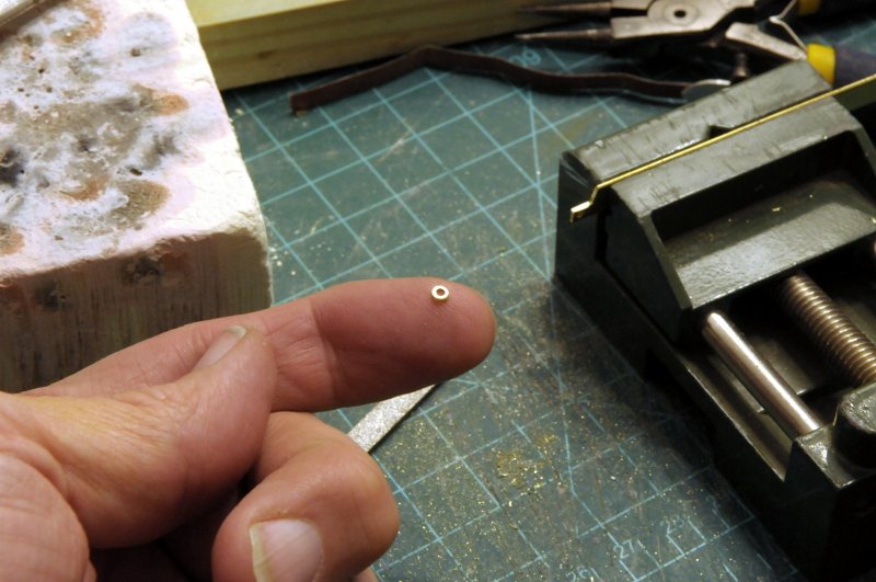
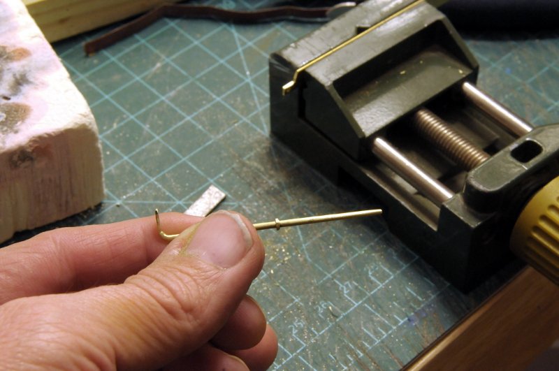
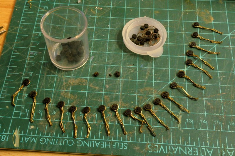
 Now that the anchors are behind me, it's time to finish up the channels and chainplates. The channels have been shaped and glued to the hull, reinforced with wire pins-- I have some brass brads, however they are too large to use as is for the bolts that fasten the preventer plates to the hull, so I need to file them down a bit. There are about 60 to do, and I thought about buying some that were the right size, but rather than spend the money and wait, I decided to do them by hand. I need to reduce the diameter of both the shaft and the head. It only takes about a minute per pin. Even with them thinned, I need to drill the holes in the preventer plates a little larger. You can see the difference comparing the ones on the left to the last one on the right (both the pins and the plates). I'll cut the pins much shorter when it's time to install them-- The work area in a more cleaned up state than usual-- Ron
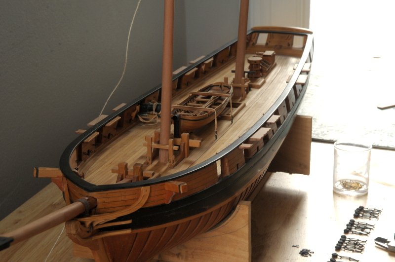
-
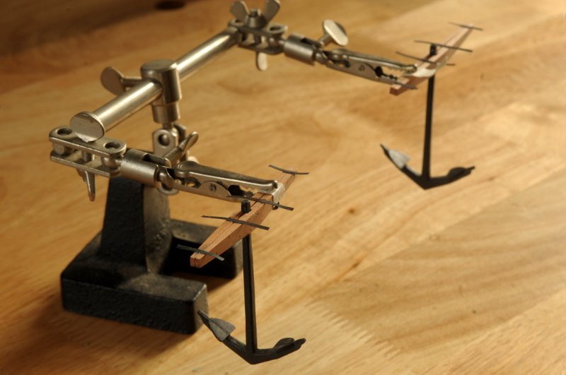
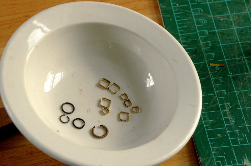
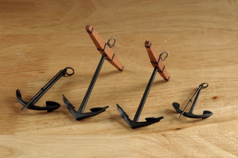
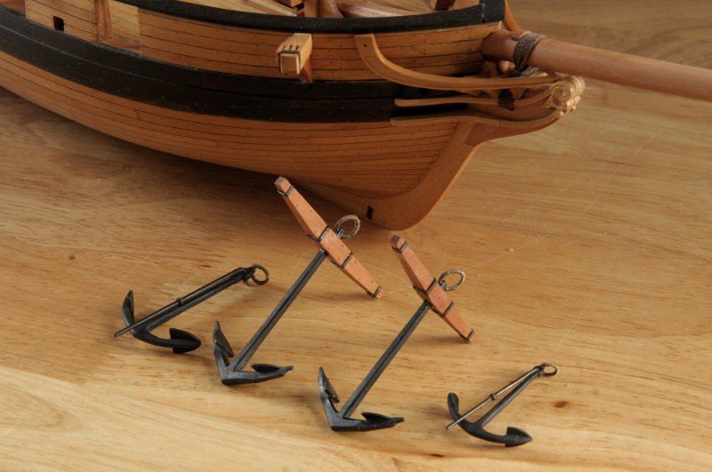
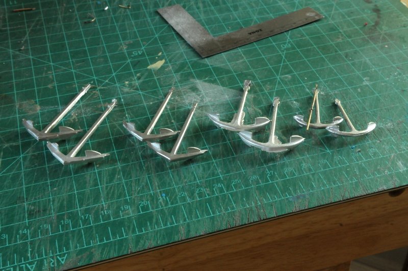
Moving forward with the anchors: Here I have blackened the straps, and anchor rings-- My plan was to epoxy the blackened straps to the top of the stocks, and once the epoxy set, bend the bands around and epoxy the ends underneath-- Unfortunately, the epoxy wouldn't hold the bands, even though the brass was paper thin, and took hardly any force to bend. They just popped off. I tried CA glue next, but that didn't work either. Plan B was to solder the bands closed, and then slip them onto the stocks. However, the brass was too thin, and melted before the solder would flow. I cut new bands from thicker brass, and bent and hammered them around this dummy stock, then soldered them closed. I then test fit them on the real anchor stock, trimming and re-soldering as necessary to get a snug fit at the proper locations on the stock-- Once I had my eight bands, they were ready to blacken. You can see I also "pudding-ed" one of the rings-- Most of the bands fit well, and they are just held by friction. I did the other rings, and here is Oneida's complement of anchors-- Ron
-
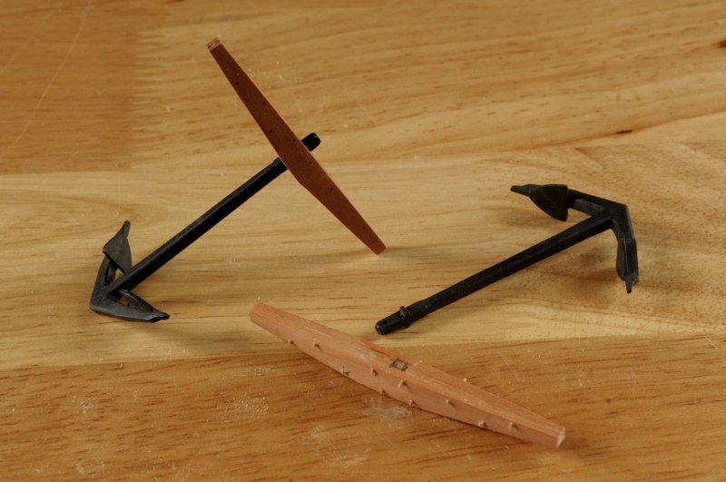
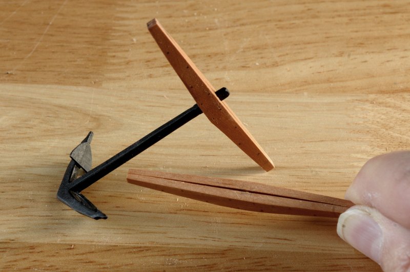
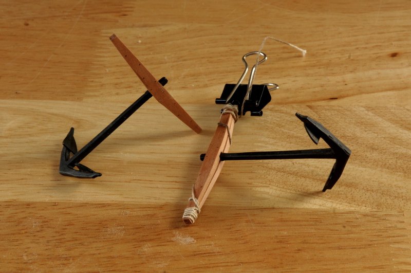
Thanks for your kind words, Mike! I could have easily used the wooden anchor masters instead of casting one-off metal copies. It was a great learning exercise, though; and I prefer the metal copies. Work continues to finish the anchors. All four of the shipped anchors on Oneida are different sizes. Here the wooden stock of the #1500 anchor is treenailed. The two halves of the stock are temporarily glued together-- Here the treenails have been sanded flush, the halves have been separated with isopropyl alcohol, and the interior gap has been shaped-- After chiseling out the interior location for the anchor shank, The halves are glued together again, captivating the anchor shank-- I pondered a while concerning how to do the iron bands. I decided that I could tape the bands, and then use those as patterns for the metal pieces. The beginnings of the Anchor rings are also shown here-- The anchor rings are here, and I slid off the masking tape patterns for the bands. Two different sets for the different weight anchors-- Unfolding the bands, I was able to cut lengths for them-- The the next step will be to blacken the rings and bands, and attach them to the anchors.
-
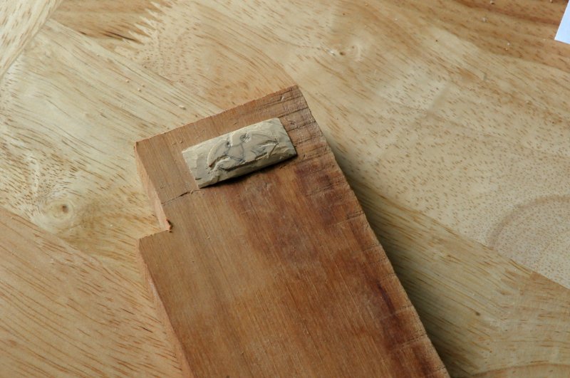
Thank you, Smo and Martin. Maybe I should have been more terrified of painting the letters! I like your suggestion of a sliver of wood to fill the gap. Ron
-
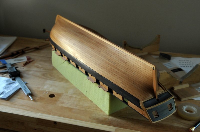
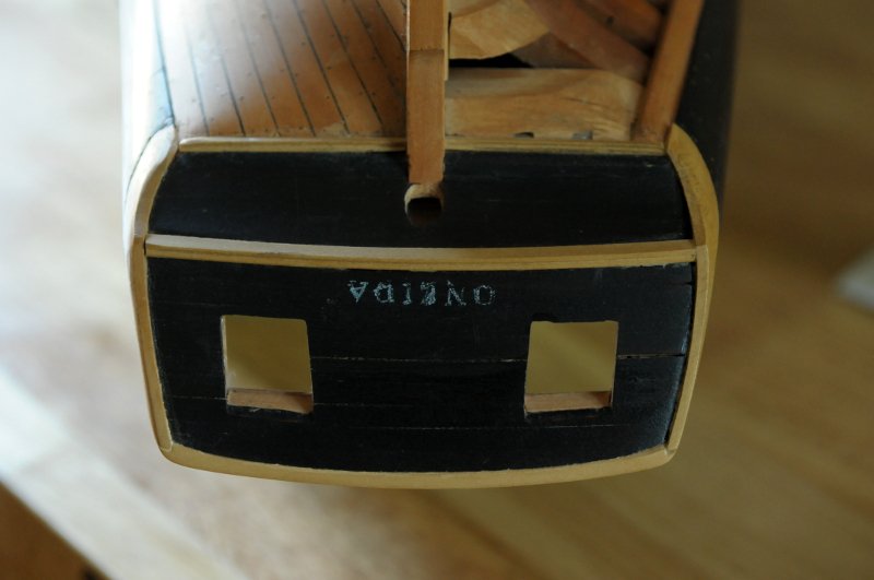
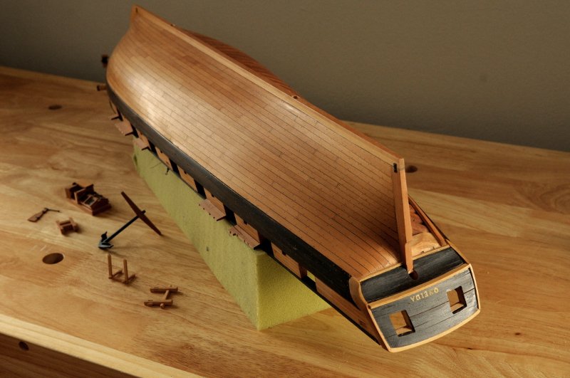
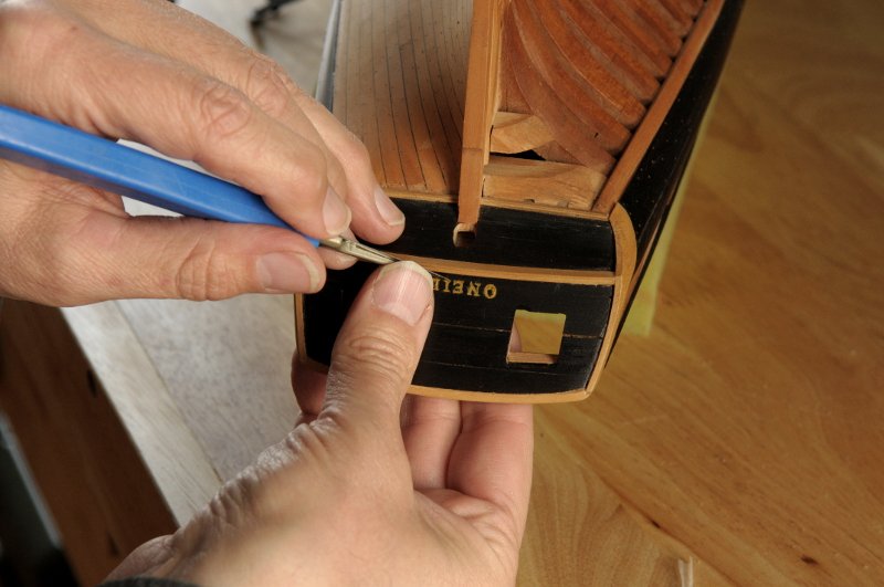
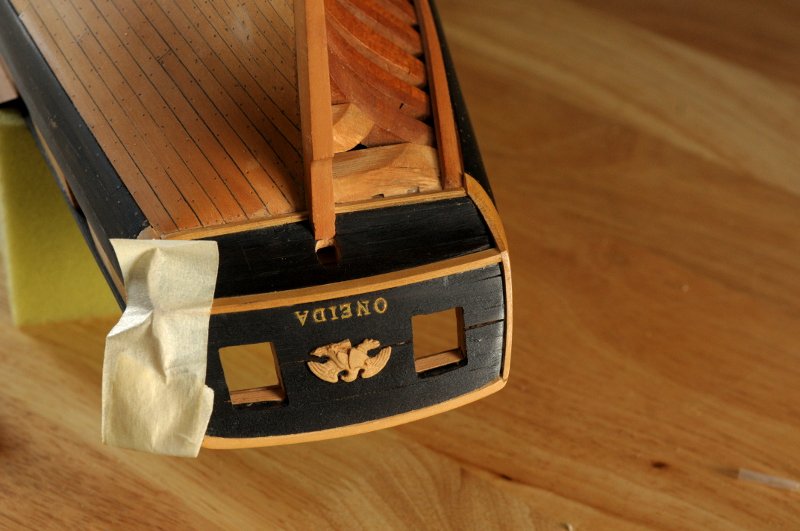
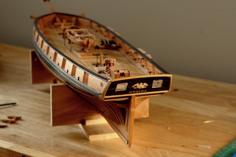
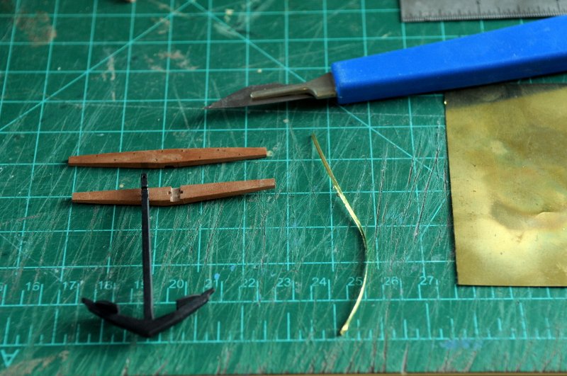
Hello All! It's been a while, about 6 months, since I've done any work on Oneida. I felt I botched some work, and it sapped my motivation completely. It's only in the last few days that I've felt ready to start (yet) again. Back in June, after finishing the eagle carving, I made preparations to paint the ship's name on the transom. I wanted to actually paint the letters, not use a decal, or transfer letters. I knew I was going to have to turn the hull upside down to do this, so I wanted to do it now, before finishing anything else. I experimented printing the name is some different fonts, and different sizes to arrive at something that looked about right. Here is the printed name, taped to the transom with a small piece of white transfer paper underneath-- At this point, I nervously turned the hull upside down, hoping I wouldn't break or lose anything. I left the ship's boat lashed down, and removed anything that could be taken off easily. This photo is after I then "colored" the lettering with a sharp pencil, which transferred the letters onto the planking. You can barely see it there on the transom-- Here's a close-up. Not too pretty. But enough to give me a reasonable guide for painting-- I used some artist oil paint, and the finest brush I have, and did the best I could. It was not very good. I didn't even take a photo. For some reason, this completely deflated me. And, unfortunately, I gave up the ship. I turned it right side up, and left it alone. Fast forward: I'm working from home due to Covid, don't get out much except to grocery shop, and when it was warmer, do some walking/hiking on the weekends. I finally got bored enough to look at the ship (actually I have looked at it often enough, but without any desire to do anything), and see if I could make some improvements to that attempt at painting the name. I turned the hull upside down again- And I set about with a knife to trim and scrape at the edges of the painted letters, trying to clean up the serifs, and the uneven thicknesses of the strokes. In this photo, all of the letters have already been given some work. It was worse before-- All the letters needed some surgery, but the ones that needed the most work were the "O", the "N", and the "D". After cleaning this up, it looked better. Not as good as I would have liked, but enough better to accept. I also had to glue a transom molding that had become detached at one end, and I glued the eagle- You can see a nasty gap in the transom planking. It was the first planking I had done on the whole ship, and it looks it. I think I can fill it with some darkened sawdust and glue. Here she is back right side up-- I've also continued working on the anchors. Here the wood anchor stock pieces are shaped, treenailed (for appearance only, for they should have been drilled through the companion piece also; but that would require a precision in which I have not the confidence), and carved out for the shank. I've cut a thin sliver of brass sheet for the iron bands that help hold it together- All for now--Happy Holidays and Joyous New Year, if I don't post before then. Ron
-
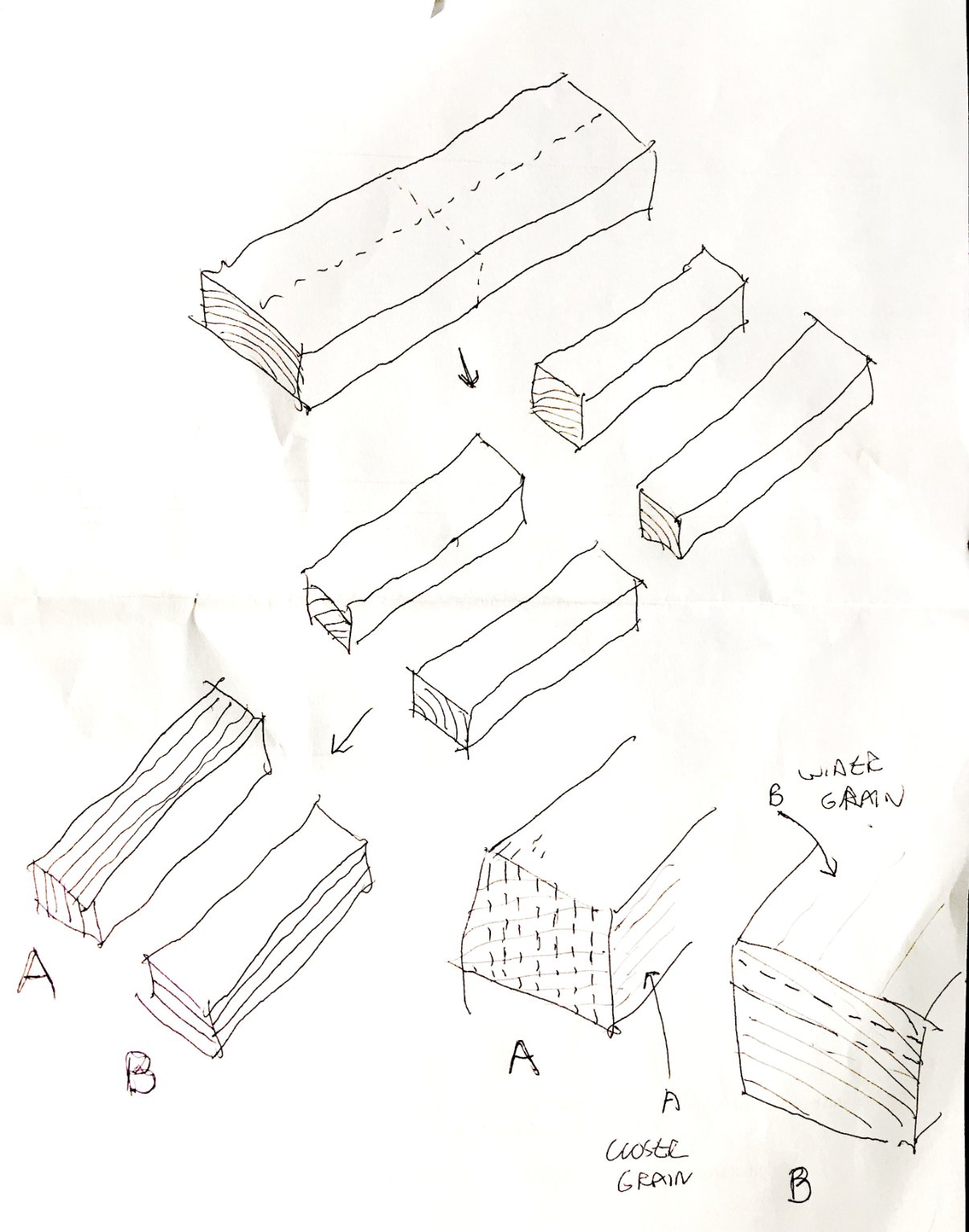
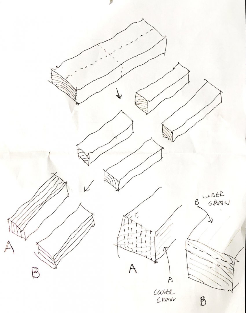
I am wondering how to go about cutting down a piece of lumber into usable billets (approx. 2" x 20" x say 1/4"). I hope this diagram makes sense-- My question is--is A or B the preferred method for the "final" cutting, in view of how the grain runs? Does it matter whether the billet will be used for framing, or if it is going to be further cut into planking strips? Ron
-
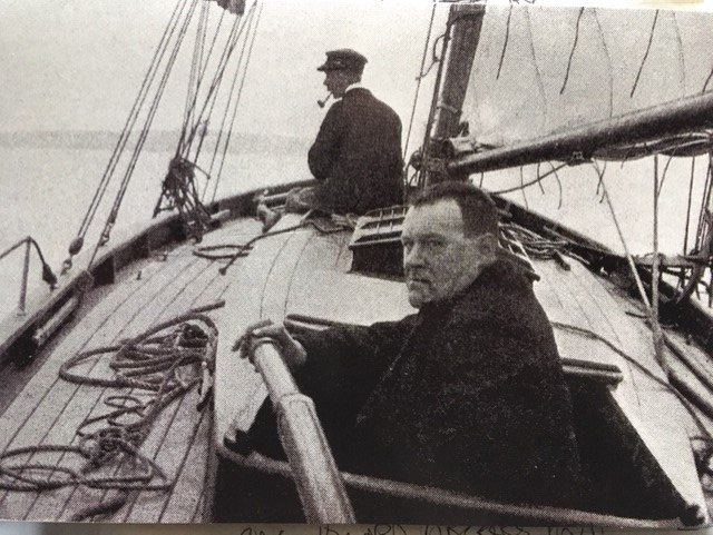
You might add Nona to the list. I think it was a pilot cutter, owned and sailed by Hilaire Belloc. Belloc wrote a great little book titled "The Cruise of the 'Nona'", in which he sails along the coast of Southwestern England (if I remember correctly), ruminating about the wonders of sailing, among other things. I've thought of trying to model this, but there is little information I've found. Just this photo (on a card from a friend who introduced me to Belloc) and some minimal description in the book. Ron
-
Looking good, Matus! I would do both decks the same, that is, if you show caulking on one, show it also on the other. Sweep ports were for oars, which were called sweeps. Ron
- 108 replies
-
- 1
-

-
- armed virginia sloop
- model shipways
- (and 1 more)
-
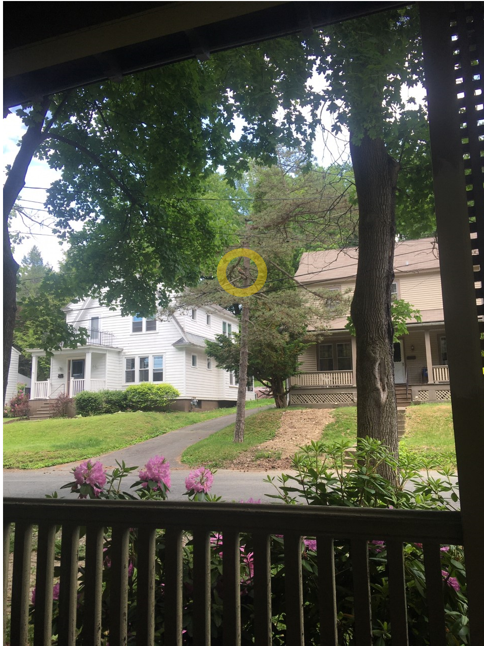
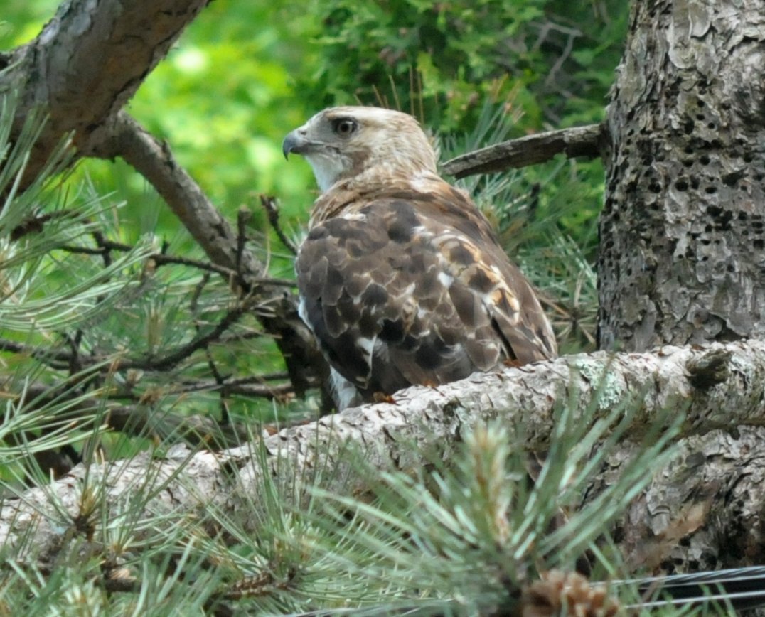
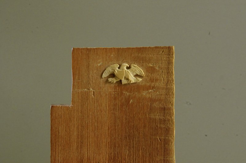
I'm calling this done. Sometimes you get to a point where you're afraid of going just too far, and messing up what you've done to that point. The beak never really materialized, there's no feather texture on the neck and body, and the wing feathers could be better (well, everything could be better), but I'm happy with this, and I'm going to stop before I slip and make an irretrievable mistake-- Isopropyl alcohol is repeatedly swabbed over and around the eagle to loosen it-- And after a while, the eagle is released-- This afternoon, from my porch, I surprisingly saw this guy (or gal) hanging out in a tree across the street-- It stayed put long enough for me to run inside, grab my camera and move a little closer for a couple of shots-- Now, that's what the beak should look like! Still, I took it as an good omen that I was done. Ron


-
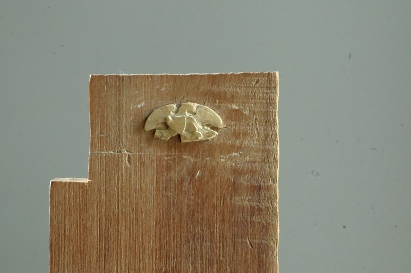
Thanks Phil! So many things to learn in this hobby. I'm enjoying the carving, though I can't imagine doing a ship with a lot more. It's very slow going at this point. Continuing to work on the overall relief areas-- At this point, I began thinking that the thickness of this piece from the "ground plane" of the flattened area was about right, and I needed to get rid of that "ground" and to reduce the overall height. Rather than shave everything down from the top, I unglued this from the base, and rubbed it on sandpaper until that "ground" was paper thin and translucent (guessing I removed about 3/128ths of an inch!). Then I glued it back, and trimmed what was left of the "ground" away. Now I am continuing to work on developing the relief-- If you compare this to the last photo of the previous post, I think I improved the shape of the shield (the curve of the right side and top, which were too flattened before), but I may have somehow reduced the width of the eagle's neck too much. Ron
-
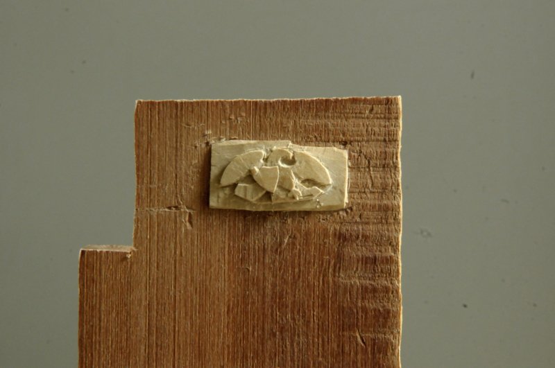
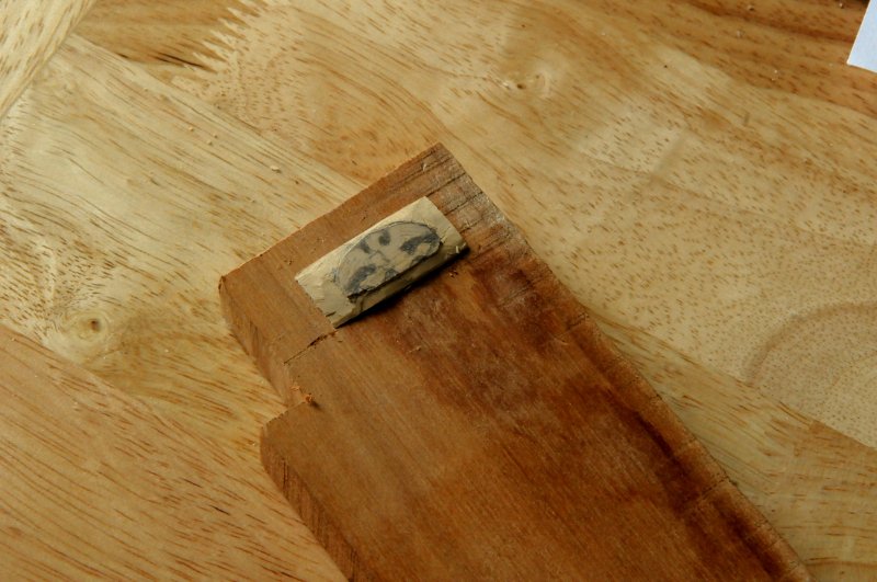
Working VERY slowly on the eagle. At this rate it will take me a good week to finish it. As I've worked, I've discovered details I missed at first (one important one being the talon gripping the shield), and I've sanded down the surface of my carving to be able to recapture those details. My model image is very low resolution, and if I look at it too enlarged, the details (like the talon) blur too much to be apparent. I have to look at it small, to see more! The outline is basically there now, and I am working on developing the basic relief areas-- I am realizing that the beak is critical to this piece, and I am holding off on its definition. It's what will distinguish this from being an eagle, seagull, donkey, or an aardvark. Ron
-
Congrats on the new home, Martin! You're moving to my general area of the country! When do you leave? Ron
- 467 replies
-
- 1
-
-
- fly
- victory models
- (and 1 more)
-
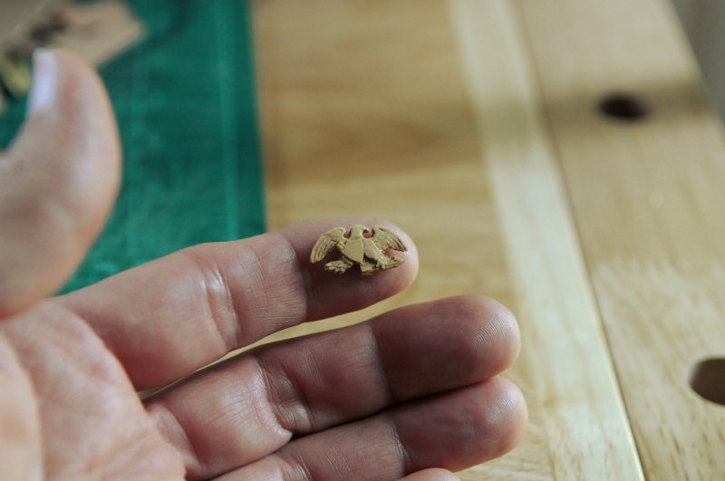
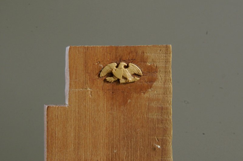
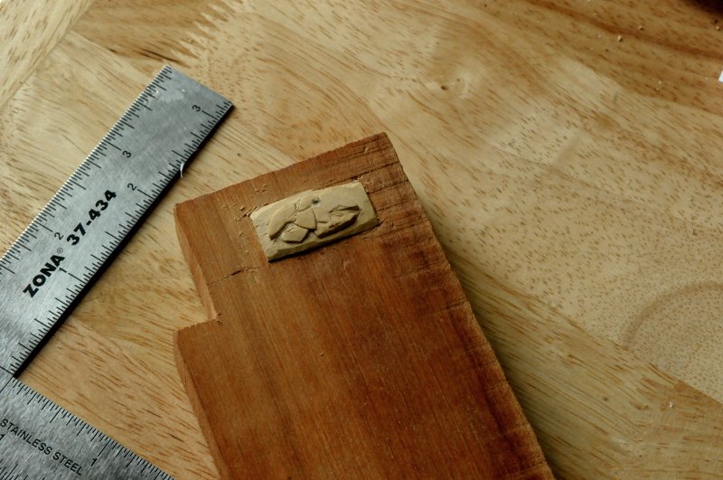
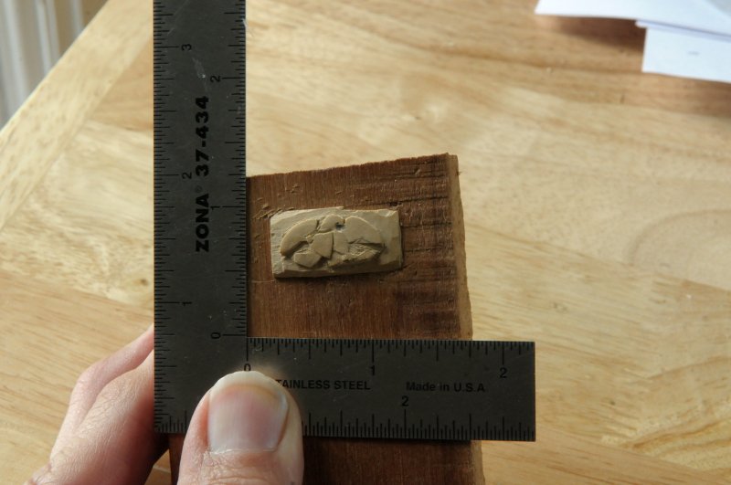
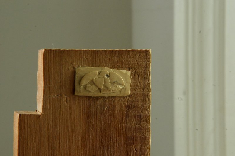
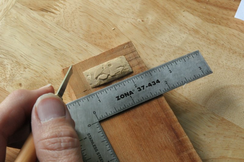
Thanks, Martin. I am using a small piece of Castello Boxwood, temporarily glued to a hunk of wood. Here is a photo with some scale context-- The eagle itself will be 13/16ths of an inch across. My birthday was last month, and I treated myself to a very nice set of micro carving tools. It was that or the Byrnes saw, and these won (and they were less expensive). I feel a bit foolish, as they are for folks way beyond my talent level, but the carving is something I want to get better at. Here is my model for the eagle-- Ron

-
Change of pace. I began carving an eagle for the transom--
-
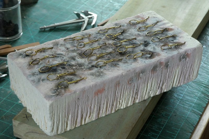
Thanks for the tip Dan. I bought some of the JB epoxy and used it. Anchors and chain plate link assemblies blackened-- Yes, I am short one preventer plate. It could be anywhere! I'll have to make a new one. Ron
-
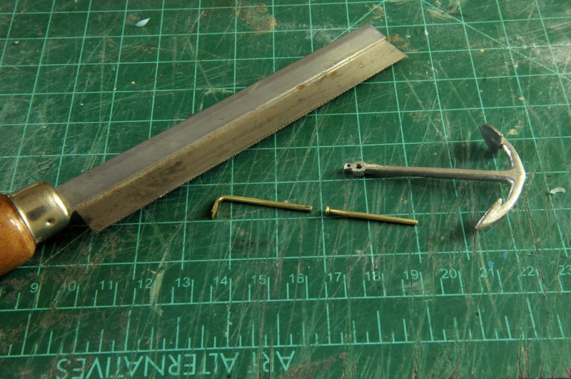
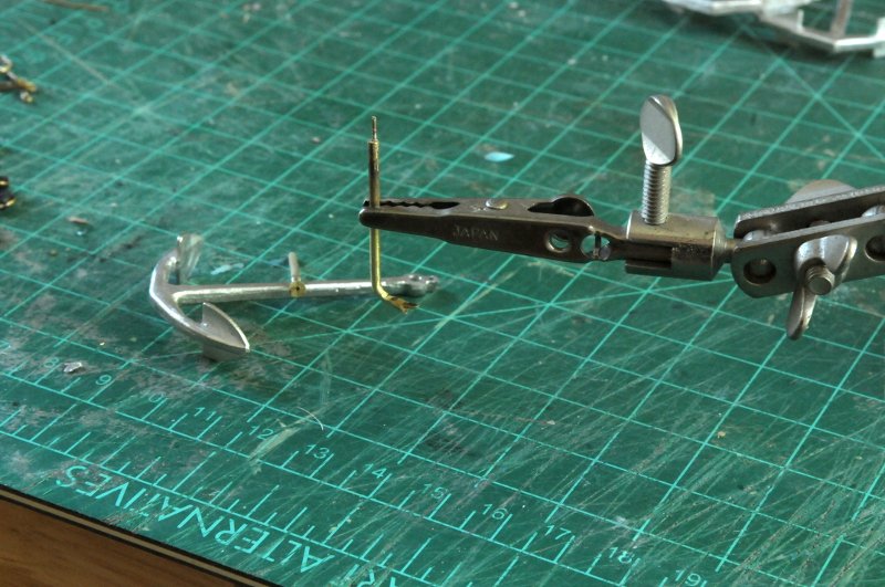
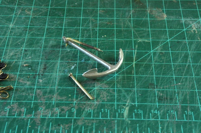
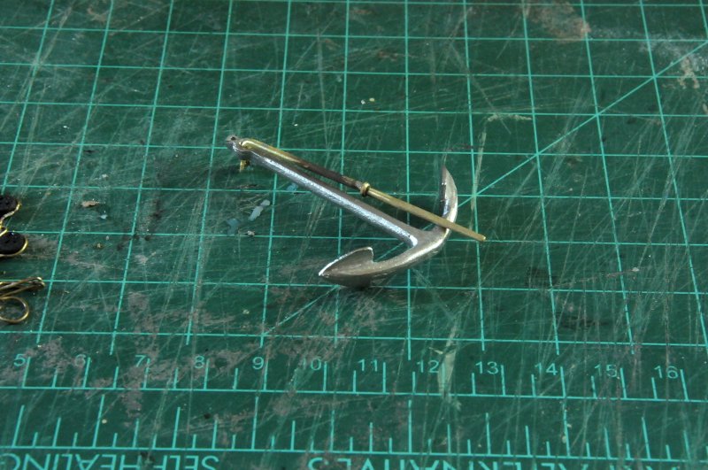
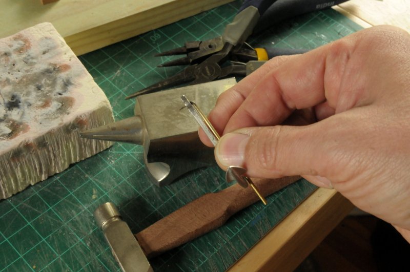
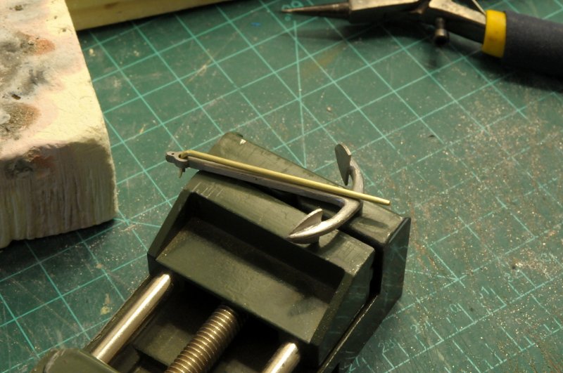
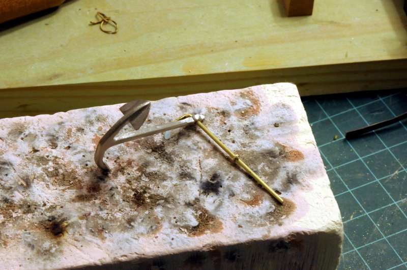
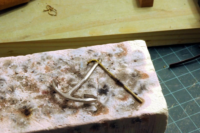
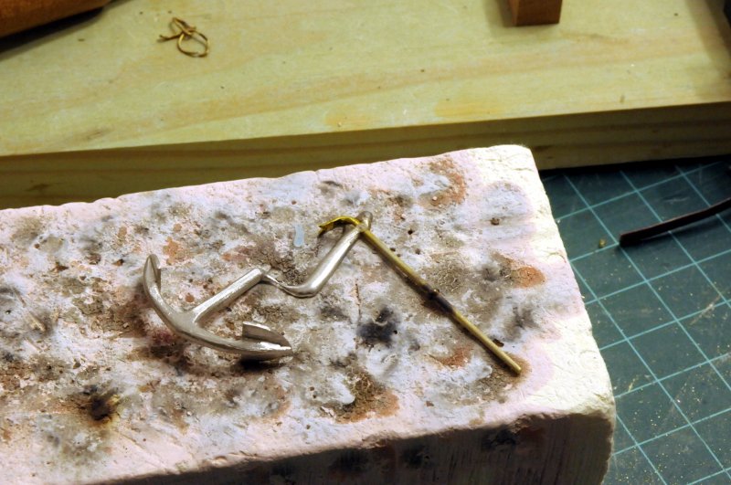
Now that the anchors have been cast, I still have to figure out how to deal with the iron stock. I'm not going to attempt soldering near the casting, and I would like to be able to use the stock I already made. I thought of hammering the "foot" end narrow enough to pass through the hole in the anchor, and then hammering it flat again, but I have doubts about that working well. I decided to saw the stock in half, with the thought of epoxying it together after blackening (I'm not sure how epoxy would hold up to the blackening process--has anyone tried that?)-- While sawing I had the thought of drilling a hole in both ends, and soldering a small bit of wire as a pin, to make a more secure joint-- Here is the pin soldered in-- My hole was drilled a bit off center (I'm a terrible machinist!), but so is the hole in the other half of the stock, so as long as I get them rotated correctly, the halves should line up well-- This is dry fit-- I admit I am tempted to try soldering the halves together, using heat sinks and wet paper towels. Maybe I'll do some experiments with an extra anchor. But most likely I'll epoxy them. The shank will be lashed down with the anchor; there should be minimal stress on the joint. Ron
-
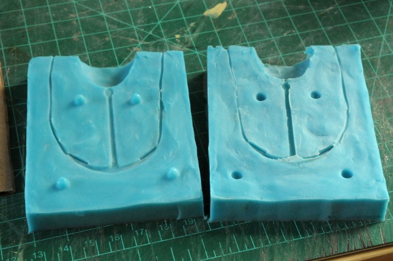
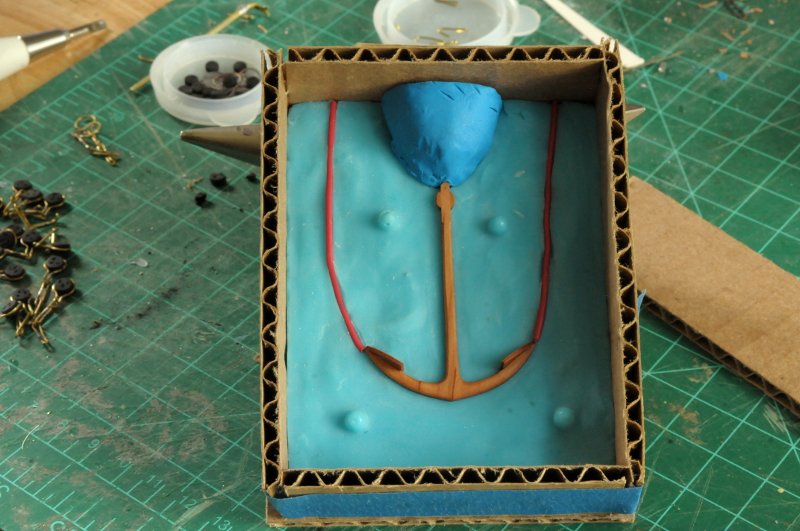
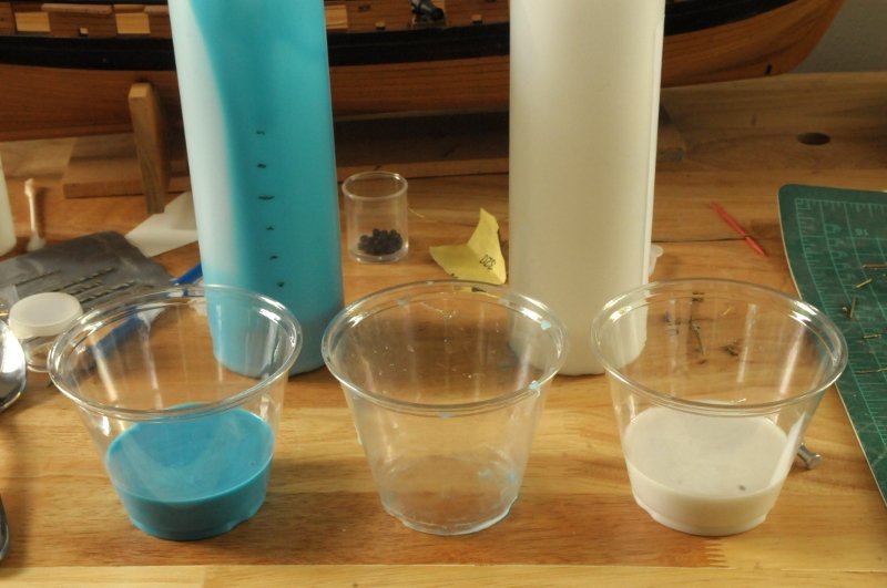
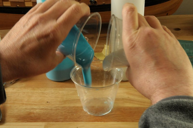
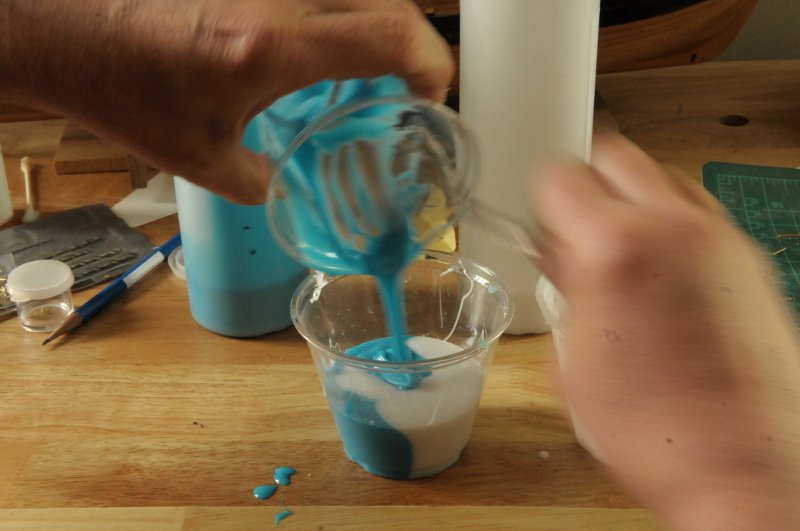
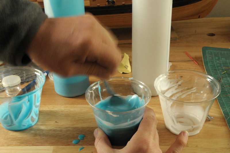
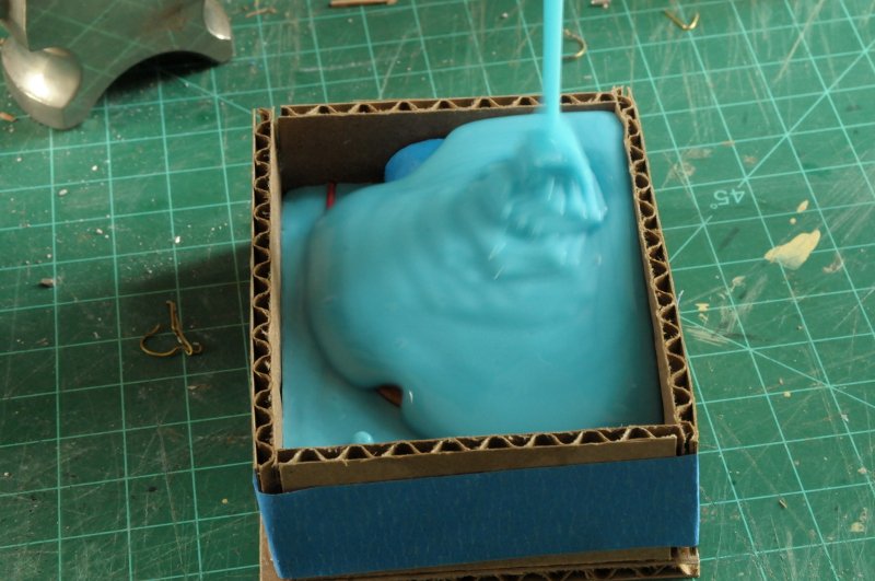
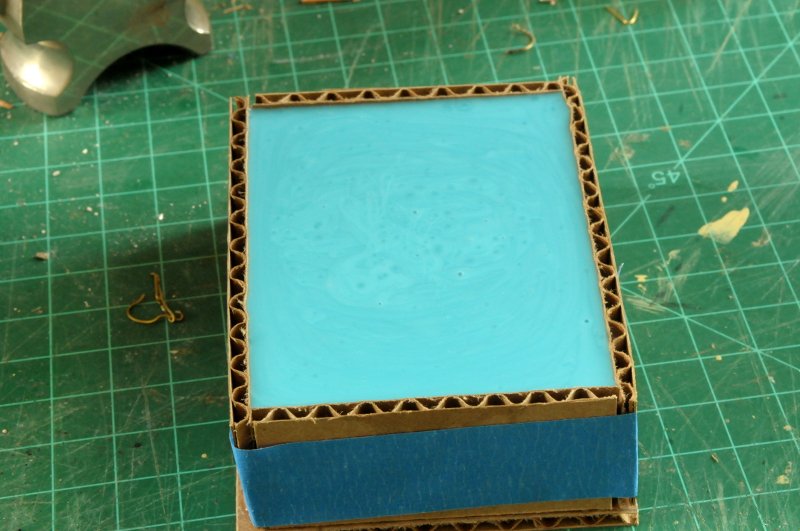
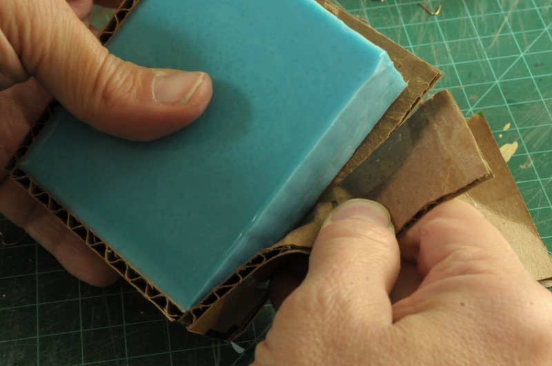
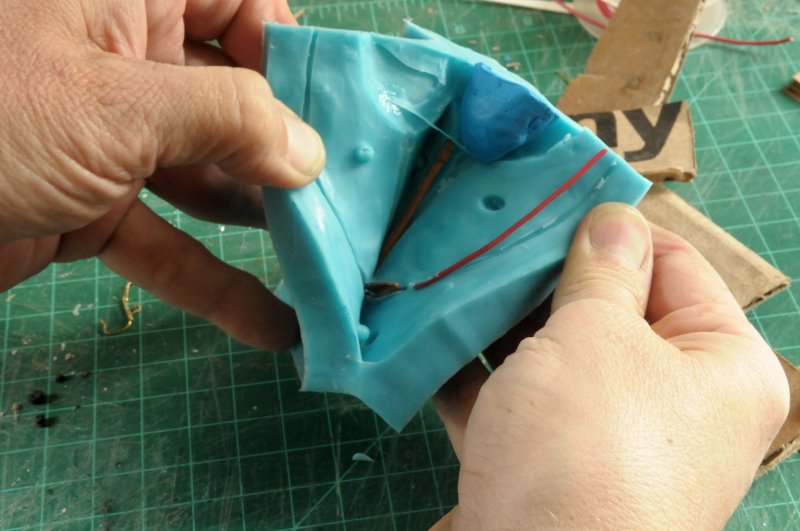
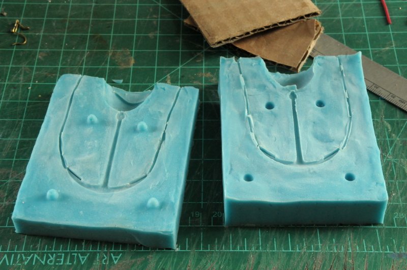
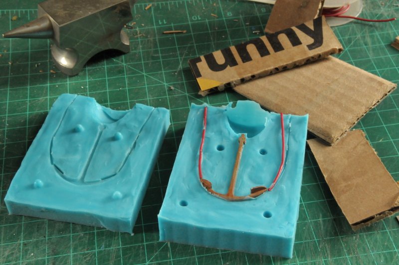
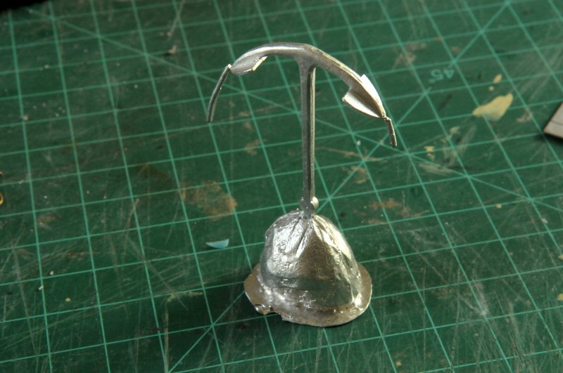
Thank you so much, Dowmer, Steve, Dave, Dan, and Martin for you words of condolence and encouragement. Martin, you are so right. These failures are a big part of model building, and I must remember they will never end! Best of luck on your workshop drawers, you will get it right! Dave and Dan, if I had thought about a heat sink (as I should have), it might have helped, though the tin alloy has a melting point MUCH lower than the silver. A little surprising to me (and maybe a result of your encouragement), I am back at it today. I decided to go back and correct the mold (thanks again Dowmer) before casting another anchor. Here is the mold in question-- \ On the right half, you can see flaps of silicone at the bottom tip of the anchor that cause trouble with the casting. As I mentioned before, the depth might also be suspect. I took the left half, built a new mold box around it, placed the anchor, made a pour head, and cut new wires to fit in the air vents. These were particularly difficult to match up with the mold, getting them to settle in correctly with all their irregular curvatures-- Here is more detailed description of the mold material mixing and pouring. I use disposable cups because after my first trial, I discovered that the two parts before mixing are messy and not easy to clean. Easier to just throw away the containers. The center cup though, can be reused, since once cured, the remnants of mixed, cured material, can easily be removed. Here I have poured the two halves, estimating the amount I need-- Now the 5 minute timer begins as I combine the halves-- I use a regular kitchen teaspoon to clean out each cup, not wanting to waste any of the material-- Using the same spoon, it is mixed in the cup-- And finally, poured into the mold-- My estimate was just a bit over, I didn't mean to fill right to the top. But better a little too much than too little-- After an hour or so of curing, the mold can be separated. First, peeling away the cardboard box-- Then peeling apart the mold. This looks a little ugly here, past instances have been cleaner-- But it's not so bad. There is a little bit of "overage" on the lower part of the anchor, but I think I can clean that up-- Here are the halves, cleaned up and powdered, ready to assemble and pour. I'm not worried about the extra flaps of silicone on the air vents, that doesn't seem to affect things-- The result of the pour-- This looks fantastic, actually. Much better than the old mold. However, there was some funky stuff going on at the head of the anchor, with the pour cap, that made this unusable in the end. But the basic mold was good, and I set about pouring some more, in this size, as well as the other sizes-- Though I never got another one of that third size without any flash at the bottom (as in the previous photo), I now have a complete supply of good anchors; and unless I have another disaster, these should do me well--
-
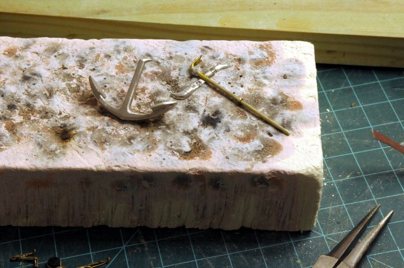
In between gluing the channels to the hull in preparation for test fitting the chain plate assemblies, I worked on the second iron-stock anchor. In the first anchor, I made the right angle bend and spread the end after soldering the stopper flange in place. It was not easy to make the bend and detail the end after it was part of the anchor, so I decided to do it the other way round, and make the bend and flatten the end first, while I had better access-- Then, I can slip the anchor on, and then fashion and solder the flange ring-- Instead of simple wire, this time I drilled a hole in a piece of brass bar stock, cut it out, and filed the flange round-- It test fit nicely on the iron stock, and I was feeling pretty good about the whole thing-- Here it is ready to solder-- I held the torch to the ring, and waited for it to glow and the solder to run. It never happened, but what did happen is this-- After it was cool enough to touch, I discovered that the ring had been soldered. Maybe before the anchor melted, I don't know. I'm not used to soldering larger pieces of brass like this. First the deadeye burning, then melting the anchor. Both through mistakes that could have easily been avoided. It's easy enough to cast another anchor. The stock is more work. This one can't be used because it can't be fit with both the flange soldered and the flattened end already done! Additionally, this was one of the anchors that would benefit from a better mold, so do I take it back that far and redo the mold? My battery of mental energy is depleted. I may take a few days to recharge. Ron
-
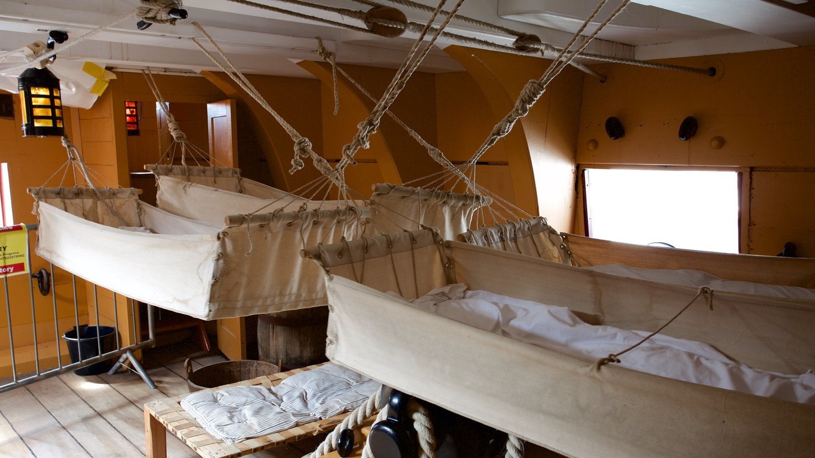
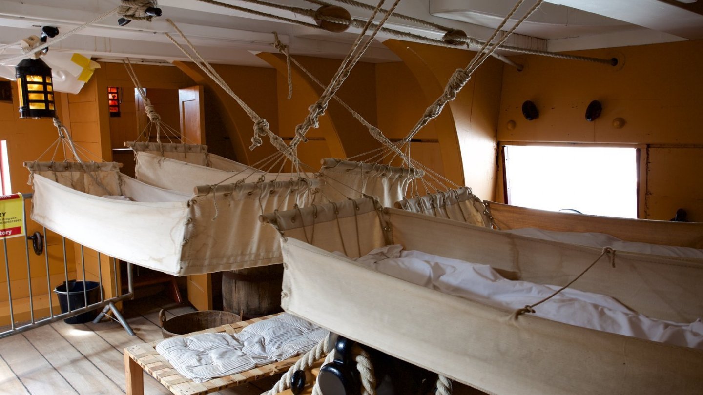
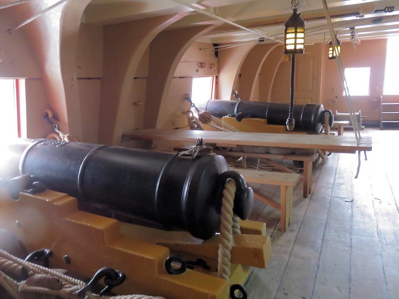
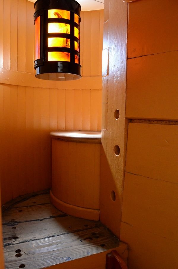
Hi Mark, You always have the most interesting questions! I'm not sure this is any help, again photos from Victory--not your ship--but the first photo shows the access door to the roundhouse as a small vestibule with a door at the deck level. You can just see the ladder steps (look under the hammocks that are in the way), and that horizontal gleam just below eye level inside is the "seat". Here is the interior of the roundhouse (looking from deck level)-- And finally from a little farther back showing the vestibule and door on the left, and on the right edge the steps leading up to the bow platform-- Ron PS. If you would rather not have these photos cluttering your excellent log, let me know, I'll delete them.
-
Heh, heh, Well, only a small update. I didn't do much on the ship today. Just work on fine tuning the shape of the binding links, and the middle links. When stretching out the middle link of the last assembly, the joint gave way. No problem, I'll just solder it back, better than ever. I laid it out with the dab of silver paste, fired up the torch and applied heat. I watched as the flux melted, the link turned red, and the silver melted across the joint. Then I smelled it--burning wood. As I moved the torch away, I could see the little deadeye glowing red around it's circumference where it was held by its binding link. I licked my fingers and gingerly pinched the deadeye, hoping to cool it and stop any damage. It was hot and still glowing as I released it. I pinched it again but dropped it on the floor. When I picked it up, it was no longer burning, but the damage was done, the perimeter had burnt away and it fell out of the binding link! In the center of the photo, one burnt deadeye, and one crushed-- I replaced it with my one remaining spare, and now I have my 20 chain link assemblies, ready to test fit. And if I have to re-solder any of them, I will remove the deadeye first!! Ron
-
B-25 Mitchell "Meet Miss Runyon" by Javlin-HK-1/32
rlb replied to Javlin's topic in Non-ship/categorised builds
I am imagining your house filled with display cases. First you see one filled with military aircraft (superbly done, by the way). The next you see is all dolls. Then another with aircraft. Then more dolls. And so on. Not aircraft in one room and dolls in another. All in one room. Ron -
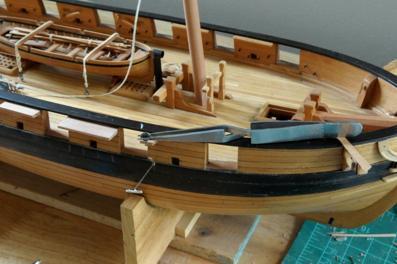
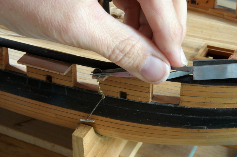
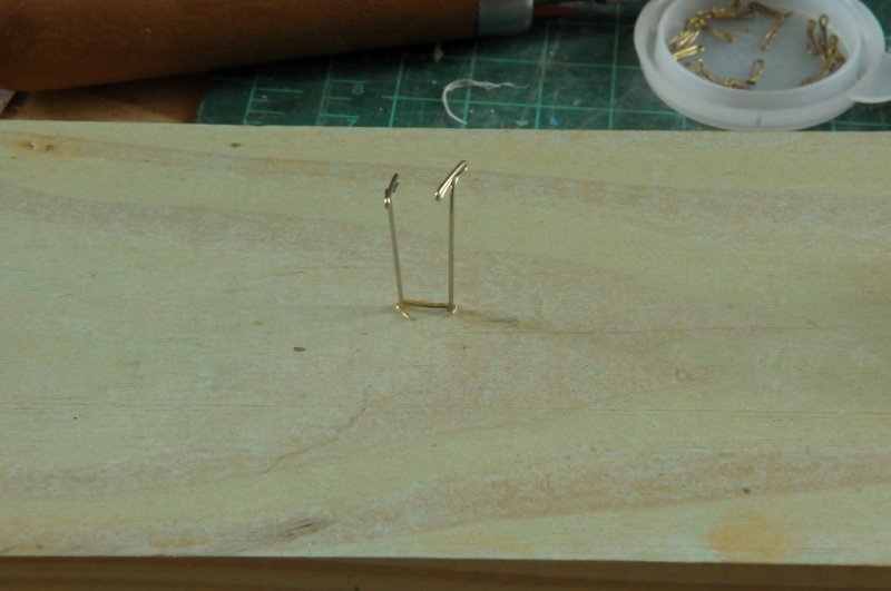
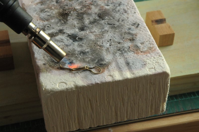
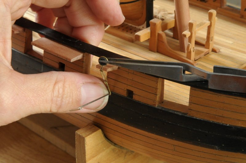
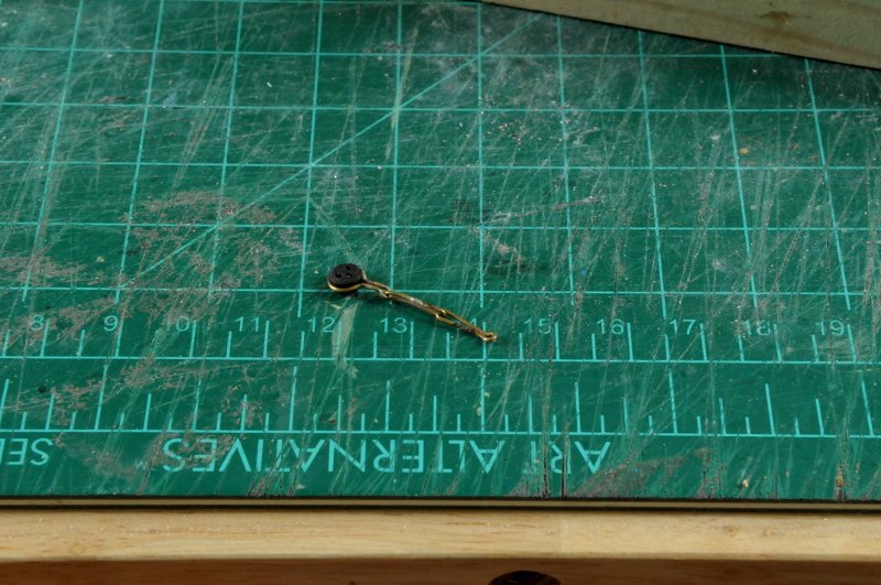
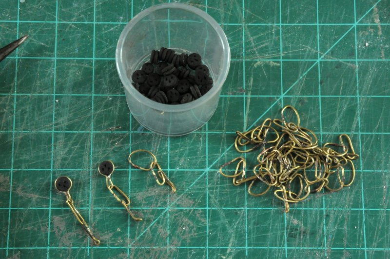
Thanks to all who have taken a look, and those who have hit the like button. Thank you, Dowmer. It is very satisfying to have learned something new, and cast the anchors out of real metal, instead of making them painted wood. The first, smallest one, actually came out the best! There are some minor problems with the molds, especially on the middle two sizes, having to do (I think) with not having the anchor forms securely and fully bedded in the first half of the mold before pouring the second, which resulted in the anchors coming out a sliver too "deep". I'm not positive that's why because I thought I was being very careful on that point. It's also possible there was some flexing in the mold with the way I held the halves together. In any event, the anchors look good, and I am almost out of mold material, so I'm not going to try redoing the molds at this time. I want to blacken the anchors with the chain plates and links, so I need to continue on with those. I have the binding links, toe links, and chain plates made, so all that is left are the middle links. With tweezers I held a test deadeye and binding link in the chain plate, and pinned a toe link to it's location on the wale-- Then I bent a piece of wire to bridge between them-- Using this piece I then put two pins in some wood, to bend a link around- I only made one, as a trial, and after removing the deadeye from the binding link, assembled all three links together, and soldered the middle link closed-- The safe way would have been to use higher melting solder on the binding and toe links, to avoid them coming unsoldered when heating the middle link. I only have one type (I think it's the lowest type, or maybe middle) but I had no problems with the other links. I replaced the deadeye, and the assembly was then test fit. On my first try the link was too long, so I shortened it by snipping it, trimming it, and re-soldering it. This time I soldered it with the deadeye still in the binding link, as an experiment, and there was no damage (meaning I didn't burn it up), so if I have to make adjustments on the rest of the middle links after the fact, I should be able to do so without too much fear. Here is the test chain link assembly-- And here it is test fit-- I made 20 or so more middle link loops, assembled them with the other links, and prepared to solder them-- I had a relatively large number of failed solder joints (six or seven). Not the already soldered joints, but the new ones. One link actually melted, and I had to replace it with one of the extra loops I had bent. One link I had to re-solder three times before I got it right! Eventually they were all solid joints. I will temporarily put all the deadeyes in, and test fit them all before blackening. Technically many of those middle links should be different lengths to account for the increasing angle of the shrouds. Actually, I'm sure many of my toe links and middle links vary slightly, so I'm hoping I can match all the assemblies to the place they fit best. And if I have to snip and redo some links, so be it. On the left is the first test assembly that is pretty much bent "to spec". The second is not finished; its binding link is only roughly to shape, and the middle link hasn't been "stretched" and straightened. And of course the third hasn't even had the deadeye bent into place-- In the course of fitting the deadeyes (so far), I crushed one. Its remnants are in the middle of the photo below. To the left of it is my one remaining extra. In the container to the left are the matching upper deadeyes that the shrouds will be attached to, and in the lid are the smaller topmast deadeyes and their binding loops. Those may wait for a later time, though it would probably make more sense to do them now also-- I'll finish putting these together, then test fit and adjust them. Somewhere in there I'll fabricate the iron stock on the larger of the two round arm anchors. Then I can blacken everything. Ron