
HOLIDAY DONATION DRIVE - SUPPORT MSW - DO YOUR PART TO KEEP THIS GREAT FORUM GOING! (Only 13 donations so far - C'mon guys!)
×


rlb
-
Posts
655 -
Joined
-
Last visited
Content Type
Profiles
Forums
Gallery
Events
Everything posted by rlb
-
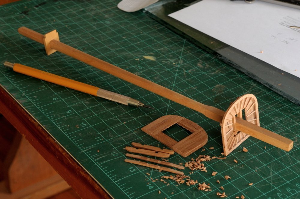
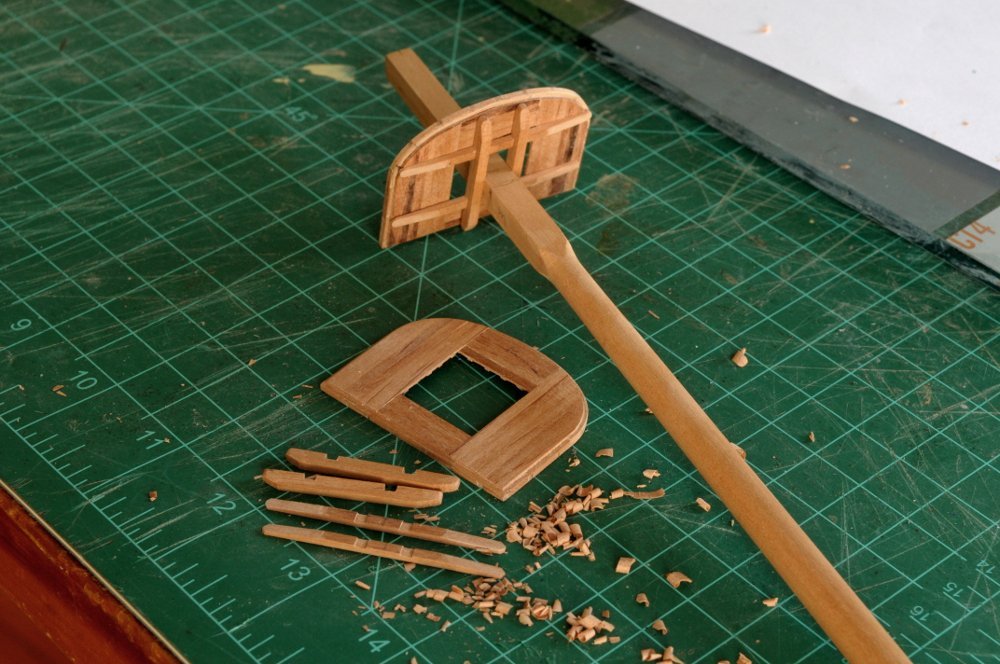
 In over 15 years, I may never have made a post with only one photo. Here it is, the current state of the mast work-- The hounds/bibs have been shaped and glued onto the masts. The trestle/cross trees are not glued. Chamfers and tenons have been cut into the mast tops. The small loose pieces are the bolsters which will be glued to the trestle trees, and the two pieces at the top are the topmast blanks. I have neglected the carronade tackle blocks, and will have to buckle down and put some time in to get caught up to my one set a day goal.
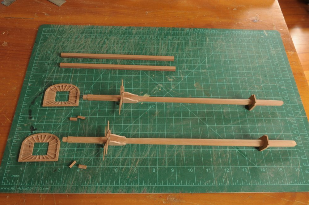
-
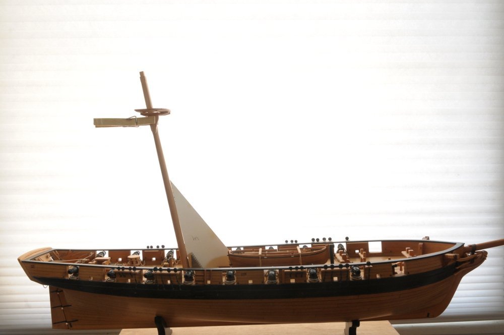
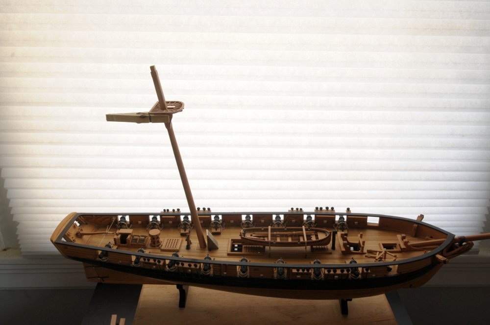
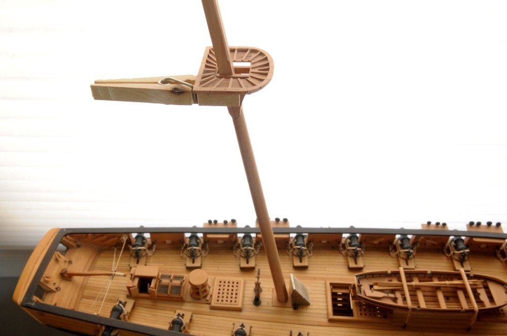
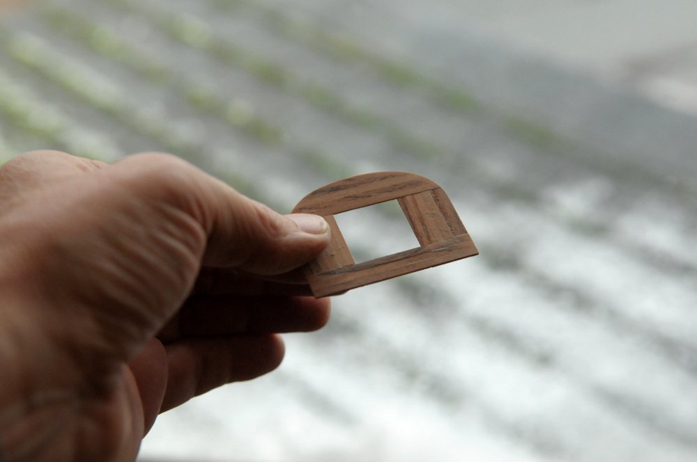
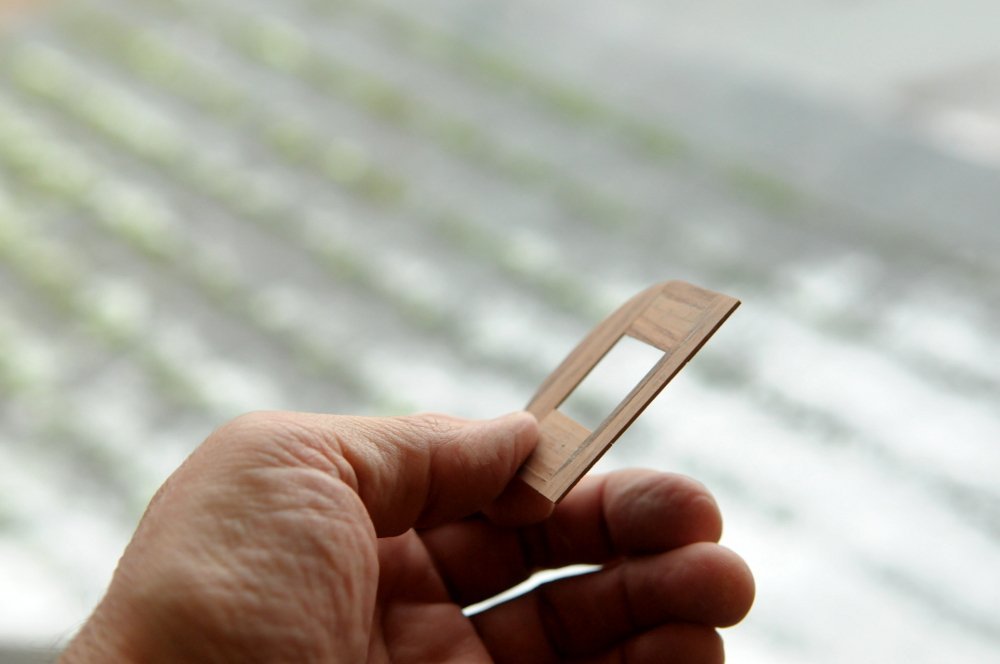
Thanks Joe! More unanticipated issues! I had to redo the trestle trees. If you look at this photo from my previous post, notice the location of the aft cross tree. There is a slight gap between it and the aft opening of the floor, whereas the forward cross tree is just about even with the forward opening of the floor. Look also at this photo of my previous post-- This is exactly how Petrejus shows it. However as I began test fitting the bolsters on the trestle trees, and blanks for the topmasts, I began to realize that it wasn't going to work. There simply wasn't enough room between the cross trees for the mast and topmast to fit correctly, and the bolster to be in the right position on the mainmast. I thought at first this might be due to the substantial rake of the mast. But Petrejus' Irene is raked also. Ahhh, I realized my error. I had scaled the top down, based on Chapelle's drawing, and the photos of the Jefferson model, whose tops, though I don't have measurements, looked by eye to be slightly on the smaller side. My mistake was in also scaling down the cross tree spacing. I had previously been puzzled that the Petrejus' trestle trees seemed too close together for the mast to fit through, and I had adjusted them for my masts. This should have tipped me off, but I didn't change the cross tree spacing at that time. Fortunately, the trestle trees were easy to remake, and I could reuse the cross trees. Here is the new arrangement-- Testing this with the mast, bolsters and topmasts, I think this will work. I could now move on to the hounds/bibs. Blanks are cut and the joints cut. These need to be thinner than the trestle trees, but I used the same stock, as I don't have any thinner at the moment. Rather than sand it thinner now (actually it also needs a slight taper), I'm going to assemble them, and then do the final sanding to thickness-- Petrejus says that all tops should be parallel with the load water line, though, curiously, Chapelle's drawing shows the tops not at all parallel to the waterline, and not quite perpendicular to the mast--somewhere oddly in between. I cut the hounds parallel to the waterline and did some rough shaping, testing it against the mast. Here it is clothes pinned to the mast, and supporting the trestle trees and top, with my template for the rake-- The top looks very slightly pitched back, but I think it's actually due to my camera not being exactly level. That also makes the rake look just a bit more than it really is- Satisfied, I now have a pattern to roughly shape the other pieces. The rake of the fore mast is less, so that top angle on the hounds will be different-- The others will be roughly shaped, tested, and then the contours finalized, along with sanding them to the correct thickness. Ron
-
Looking great, JJ! Ron
-
Congratulations James! And whatever was the impetus, I am deeply indebted to you for starting this site. Thank you. Ron
- 488 replies
-
- 8
-

-
- Indefatigable
- Vanguard Models
- (and 1 more)
-
Thanks Dan, and thanks for looking in. With the tops basically formed, I set about making the cross trees and trestle trees. After the complexity of the tops, they were pretty straightforward. The main and fore set do need to be slightly different, as the dimensions of the fore mast are very slightly less than the main mast. Here the main mast trestle and cross trees are temporarily assembled. There will need to be some adjustments to the length of the pieces-- The main top assembly was then checked on the main mast to make sure the trestle tree spacing fit the mast. The mast top was measured before the notches were cut into the cross trees-- The foretop assembly will be checked as well. You may notice that I worked on the top cleats. The break of the slope is better when the cleats leave the rim. I am working backwards from the tops, to the trestle/cross trees, to the mast. The bibs will be made and shaped soon. All is still in progress. The shroud futtock plate holes need to be mortised into the tops, as well as some other rigging preparations. Bolsters need to be added to the trestle trees, and refinements need to be made to the masthead above the top. On most ships there is a railing on the aft end of the top. I am omitting it, based on the US Brig Jefferson model by Glenn Greico, which is a similar Great Lakes ship from the same time period. Ron


-
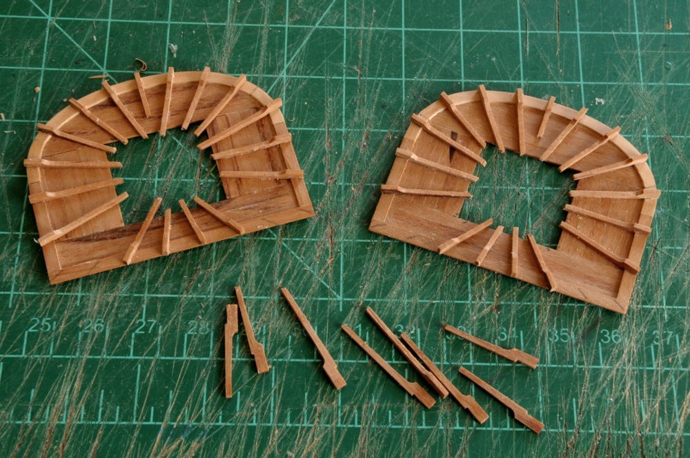
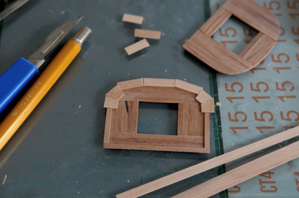
I determined that I needed to redo eight of the cleats. If I were a perfectionist, I would have had to do more (strike that, if I were a perfectionist, I would have to redo them all--for reasons to be noted later). There were a few that were barely passable, to my standards. So eight is enough-- The eight were made with an extended 'big' end. After gluing these in place, work was begun infilling the rim with chocks. Time consuming little pieces--a different angle at each end, and the front ones had to be filed with a curve on the inside, with the outside to be sanded down after all the chocks are glued in. The top on the right has had all chocks installed, the one on the left is in progress. And here are the tools used for them (actually there were a couple additional files, and a disc sander used to fine tune the angles)-- After gluing in all the chocks, the sides and back were sanded to even out the projecting cleats, and the front sanded to finalize the curve. Then the top was sanded flat to even out and reduce the height of the rim. Something to note: the three chocks on each side of the top are wider, to accommodate the shroud futtock plates that will be mortised through them. They actually overhang a tiny bit on the inside of the rim beneath (which is how Petrejus shows it)-- And now the reason all the cleats should be redone: the break from the flat top of the cleat (embedded in the chocks) to the slope should start where it leaves the chock. Only a few here and there actually ended up breaking at the right spot. AND the break should have led to a more gradual reduction in thickness. I will do some cutting and filing to address the break points, but the slope still won't be quite right. Oh well, I'm pleased with the outcome (though they're not finished yet!)-- Seventy some pieces of wood in each of these. Ron
-
Thanks Toni! Nice to know folks read the text as well as look at the pictures! Aahh, JJ, thanks so much for that info!! I didn't know there was a difference between isopropyl and denatured alcohol. Now I do, and I'll get some. Ron
-
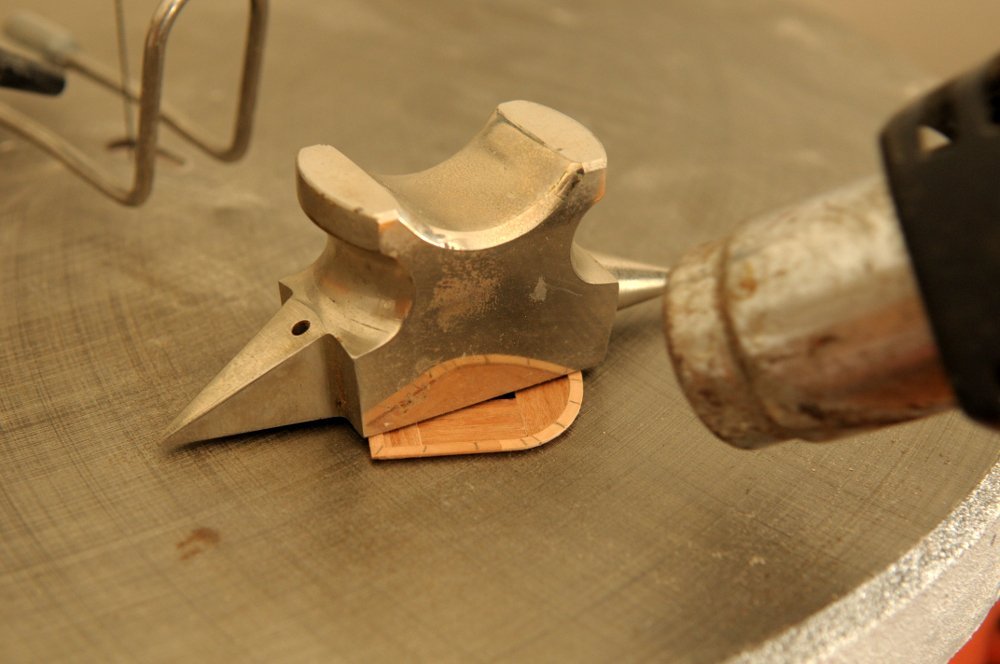
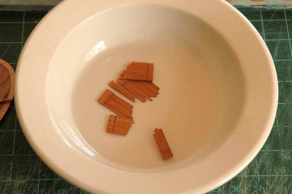
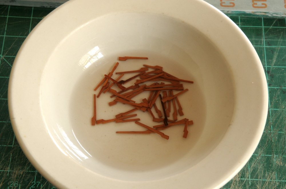
Thanks, and you're welcome, JohnLea. I hope that what I have here is useful for others. With that in mind, more progress on the tops. I had a very slight warp in one of the tops. The front part curled upwards maybe a millimeter, or a bit less. I've been keeping it under a weight most of the time, but that hasn't helped. Getting the idea from Blue Ensign's log on HMS Indefatigable, I tried a heat gun on the piece. I wasn't sure I used enough heat, I was a bit nervous about it. But it seems to have worked, and it is flat now-- I cut a bunch of blanks for the radial cleats-- And glued them together with the barest bit of glue at each end, so they can be uniformly shaped-- They first needed to be sanded flat on one side, and the aligned ends squared-- Then, with knife, chisel, and file, I made a shallow notch on one end. A good mill would have done this well, and though I sometimes use my rotary tool in the stand as a mill, I felt it was going to be too difficult to be as precise as I needed to be here. The pieces are so lightly glued that they didn't stay together, and now I have four groups. You can see how the notch fits over the rim of the top-- As I began to shape the tops of the cleats, one broke off, and I shaped this one individually, as a master to guide the rest-- My procedure ended up being to file the rounded part at the 'big' end first, and then chisel and file down the flatter part. It's not exactly flat, it does have a slight taper to the end-- A few more groups broke apart, but here they are shaped and lined back up-- Into the bath of isopropyl alcohol-- I'm very impatient with this alcohol business. I've never been able to wait until pieces just fall apart. After a couple hours the glue was weakened enough that I could pry them apart with my fingers, without worrying about breaking them-- Out of the bath they dried quickly and they were test fit to the tops-- I did not anticipate that the severely skewed pieces along the back of the top, especially the corner ones, would need to be different, with the 'big' end lengthened (and/or the notch underneath cut farther back). I'll see if these are salvageable, but I may have to remake a few cleats. The big ends are just a bit taller than they will be when finished. There are chocks that will need to be fit between each cleat, on top of the rim, and then when all is glued up, the rim will be finally sanded flat to the correct height. Ron

-
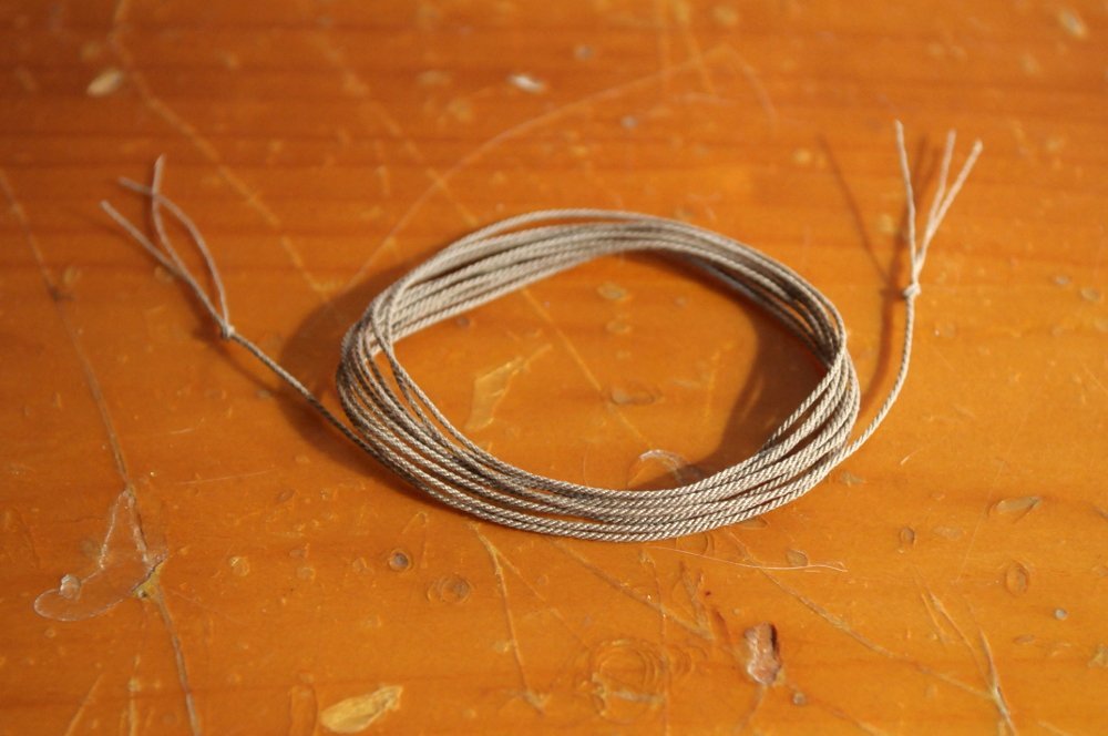
Thanks Chuck. And thanks for making the Youtube videos. I would have been lost without them. Tying the thread to the eyehooks with somewhat even tension took longer and was trickier than making the rope itself! We'll see if future attempts go as smoothly. I need to make anchor cable, and I have to figure out (maybe by trial and error!) which direction to twist everything. Ron
-
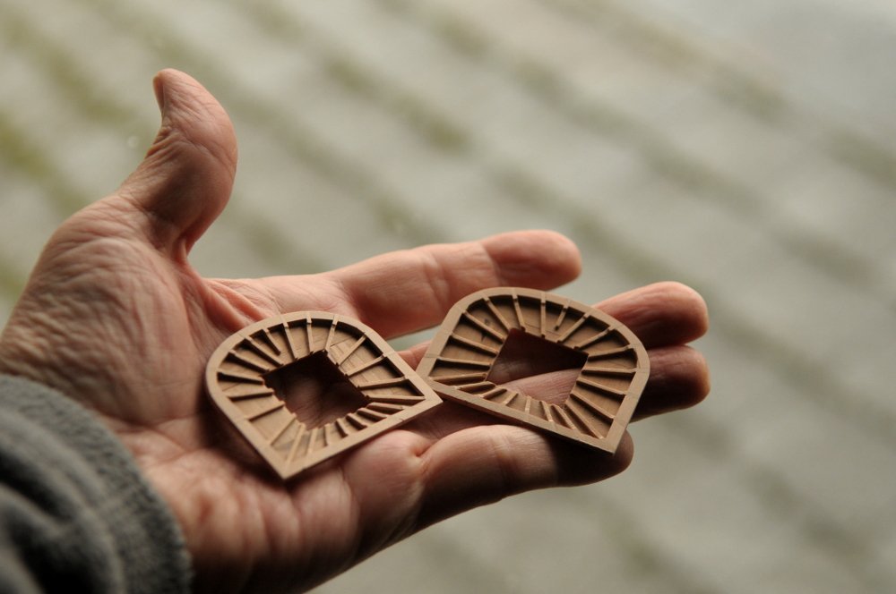
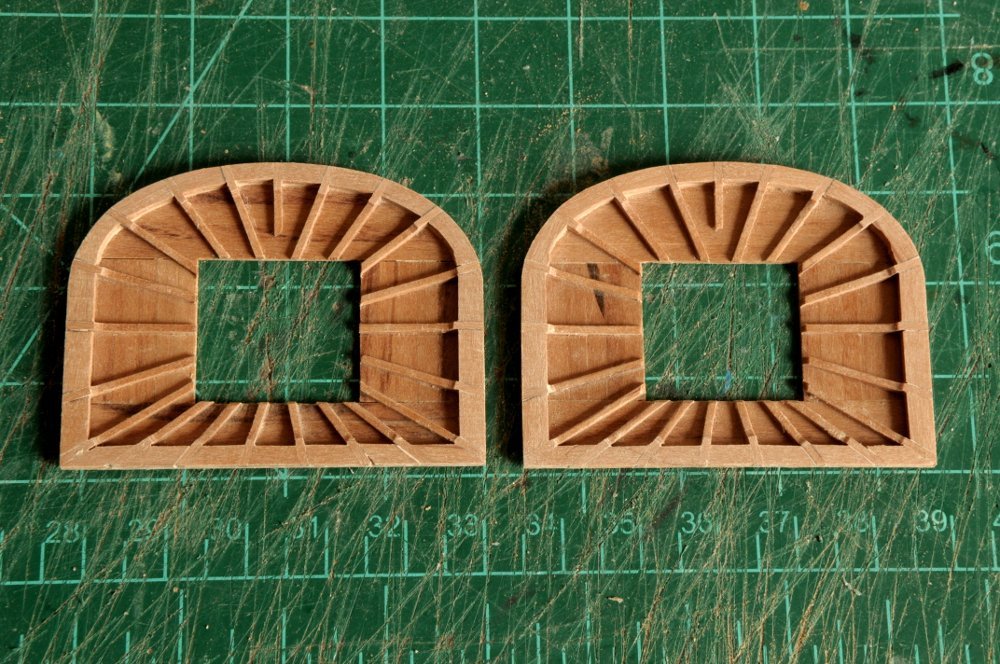
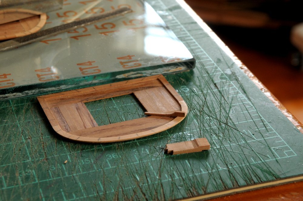
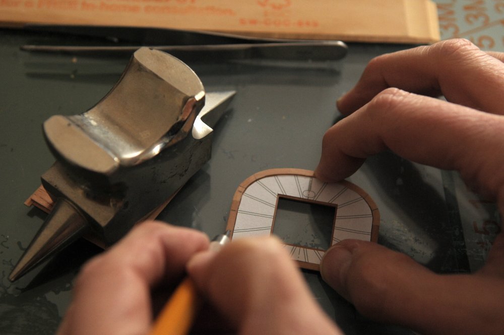
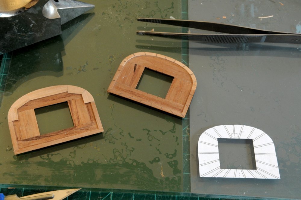
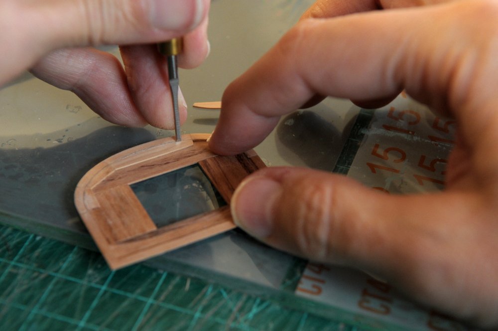
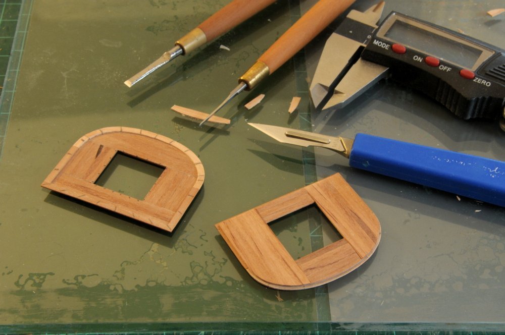
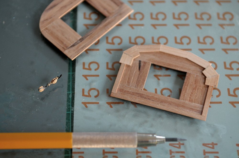
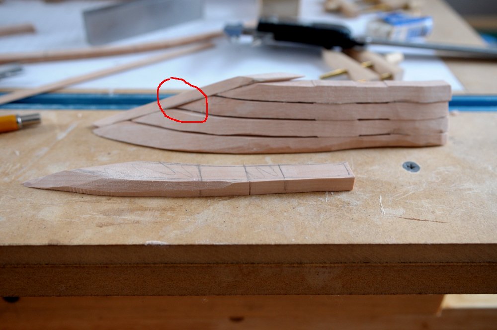
The front border of top #1 was shaped, and the same procedure followed for top #2. I did reduce the number of sections in the curve- The light pencil line was traced from the BOTTOM side of the top, just as a check to make sure the pieces would fill in the curve correctly. Next, it was glued to the floor along just the curved edge. While that was weighted and drying, a paper template was placed on the floor within the rim of top #1, and the locations of the radial cleats was marked-- Here the front edge of top #2 has been sanded-- The line of the back edge has been drawn by eye in pencil, and the piece is scored lightly with a knife, repeated a few times, but not cut all the way through-- The waste is cut away with a chisel because I felt I had more control and didn't want to cut into the floor below, as I knew there would need to be some refinement of the shape. There is no glue under the waste area, so once the chisel cuts through, the pieces detach easily-- The width was checked with a caliper, and further shaped where needed with sanding on the outside edge, or the knife and chisel on the inside edge. Here is the current state of the two tops (one upside down)-- Oh, and I did today's pair of carronade tackle blocks. Ron
-
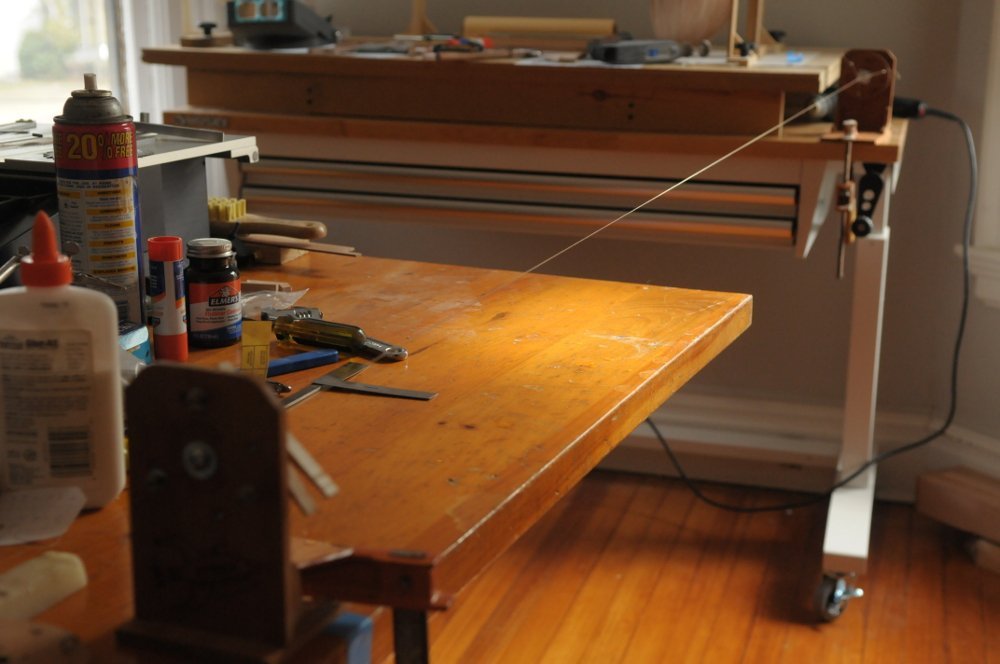
I purchased Chuck's ropewalk a couple years ago. I put it together at that time, but was too intimidated to use it (and I didn't have a pressing need for any line). With my fresh shipbuilding vigor, I decided now is the time to take the plunge-- I figured I would have many failed attempts before I got the hang of it, but it worked out great! Maybe beginner's luck, but on the first try I actually ended up with a decent rope-- I think it could have been a little tighter, and it's not any particular circumference or diameter that I need, but I'm confident now that I can make what I will need for Oneida's rigging. On to the top(s). I cut and glued up the floor for the second top, and started on the piece that overhangs the edges. No problem on the straight pieces, but the curved front is a challenge. I don't have an easy way to make a piece large enough, at the thinness required (about 1" scale) to make it in one piece, so I thought I'd do it this way-- Very tedious, but I think this will work, if it doesn't disintegrate when I shave it down to match the curve of the top. This (and the straight pieces) need to overhang the floor halfway-- I also completed another pair of carronade tackle blocks. My goal is to do one pair a day. If I can do that, they'll be done in another couple weeks! Ron
-
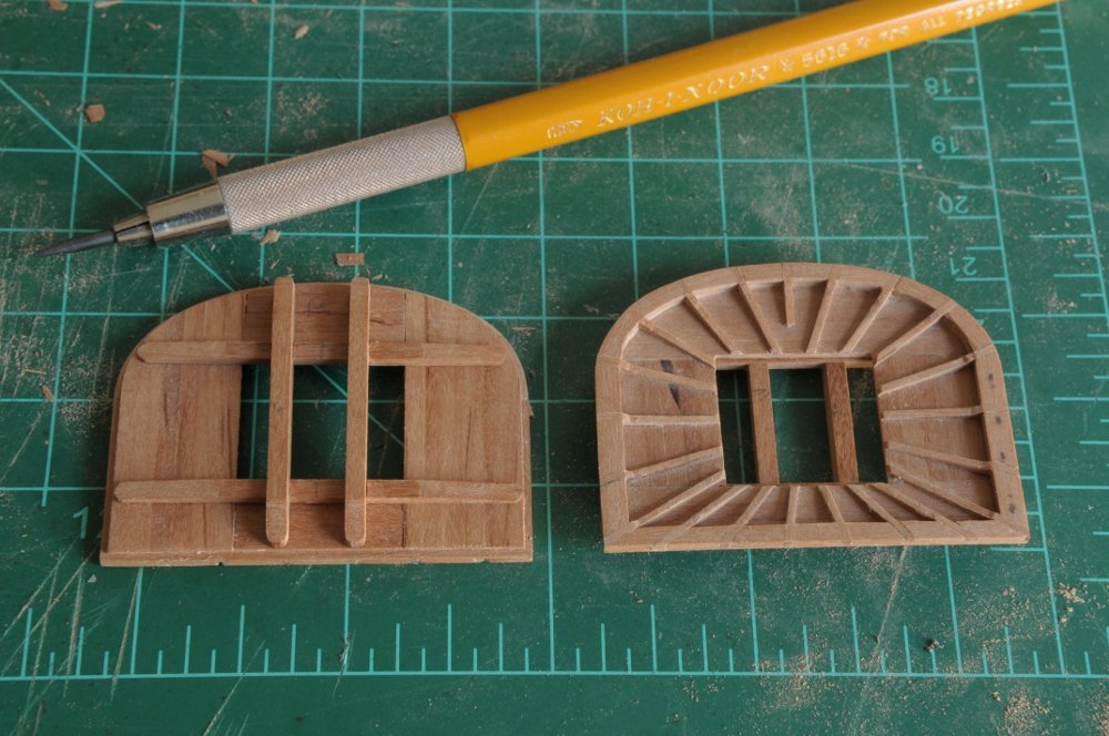
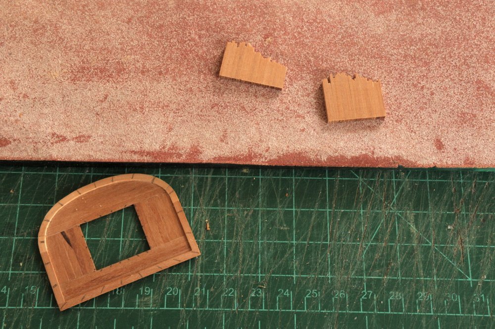
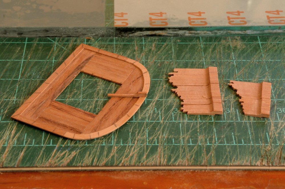
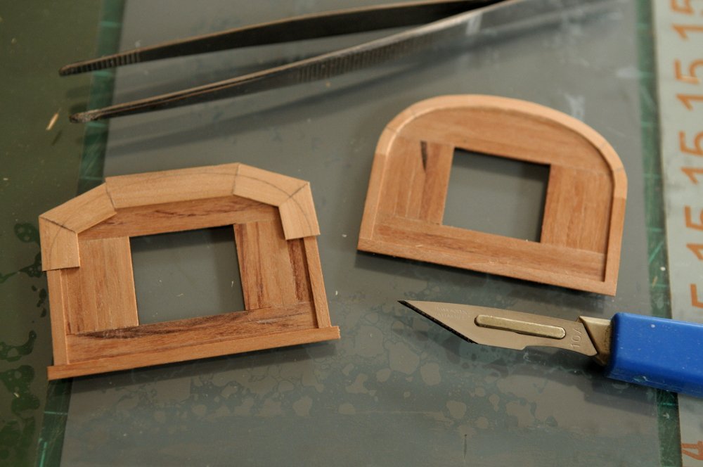
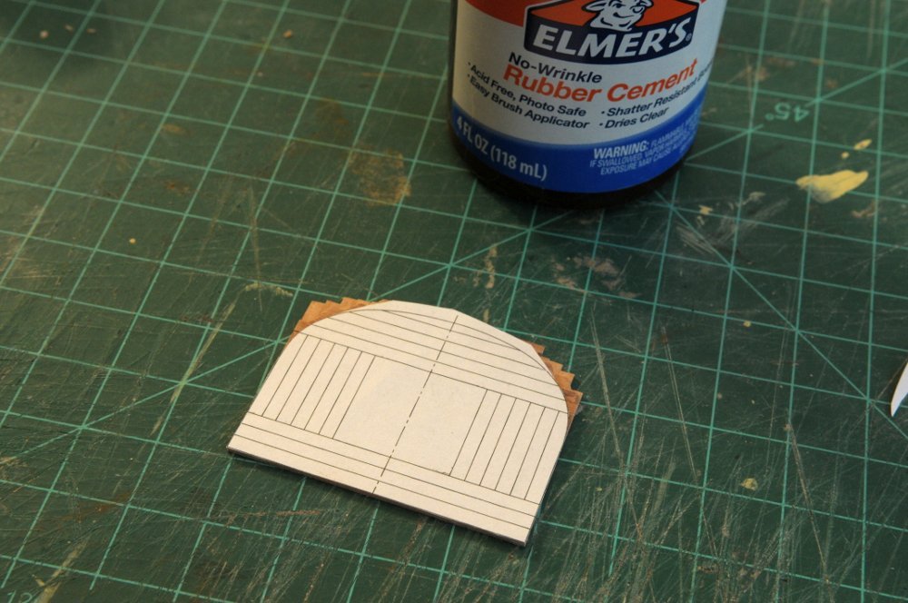
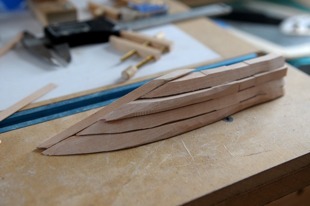
Thanks, Ed, for the encouragement. I can't predict when the urge to work takes me, but it's on for the moment! I continued on with the top. Both the main and fore top will be the same. I ended up using a very small chisel to pare down the glued up sections of the top, so they would interlock as Petrejus described-- The photo below shows that I have some more work to do before the overlap sits flush-- Once I was satisfied, I glued the pieces together-- After the floor of the top was one piece and the straight areas trimmed, I rubber cemented the pattern to it, to sand down the curved areas-- After sanding the curved area-- This is about 1mm thick-- Just a note on the color of these pear wood strips. For the first time, I've cut my own strip wood. The darker streaks are burn marks from the saw blade. Another learning curve to master. The tops are going to be stained black in the end, so it's okay. In fact, once it's stained I don't think you'll be able to see that there are 20 individual pieces making up this floor. Petrejus says there are 65 pieces in the finished top. I didn't make any more carronade tackle blocks! Ron
-
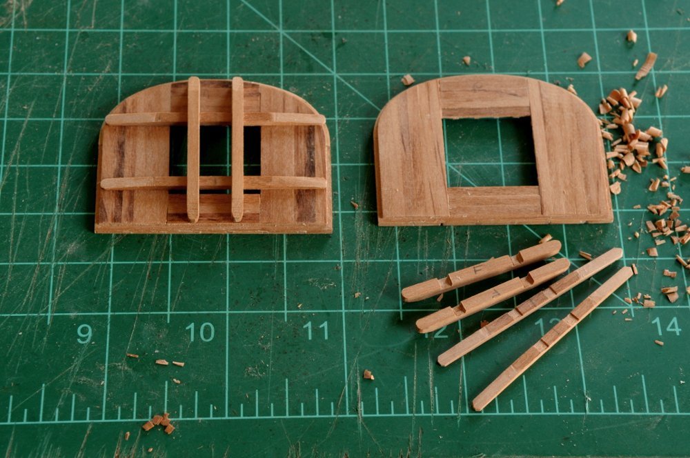
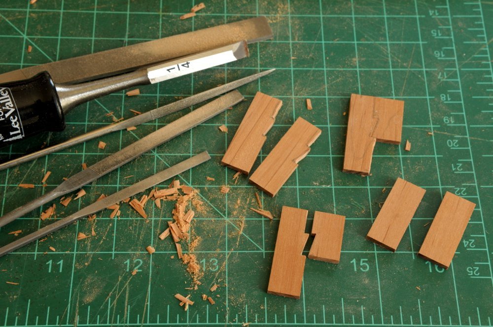
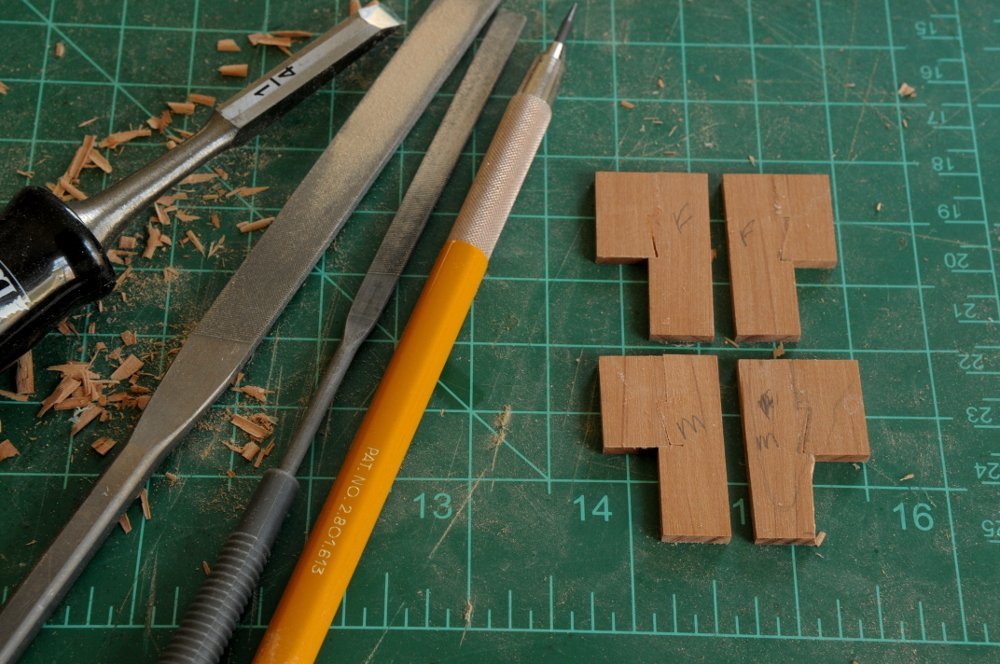
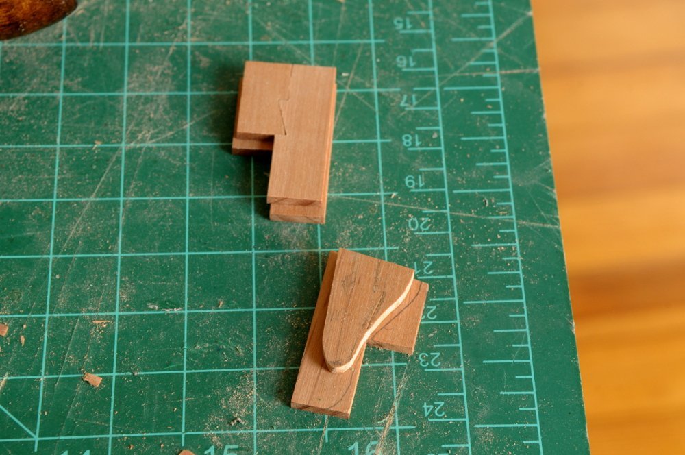
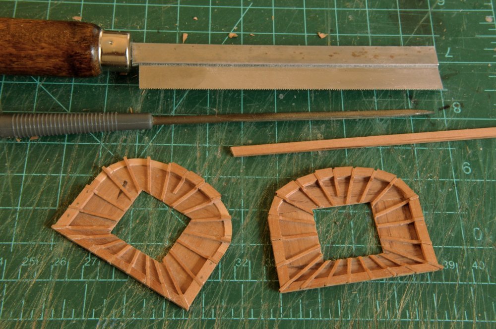
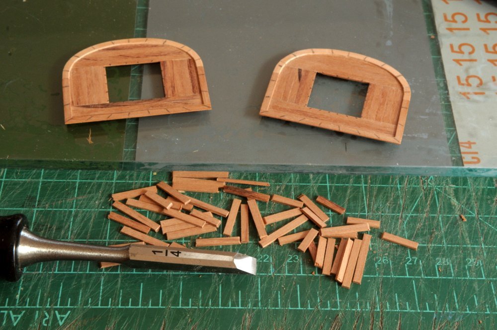
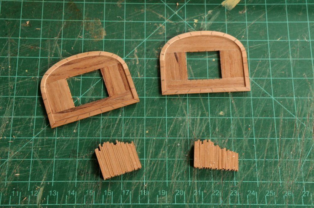
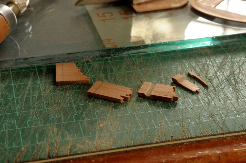
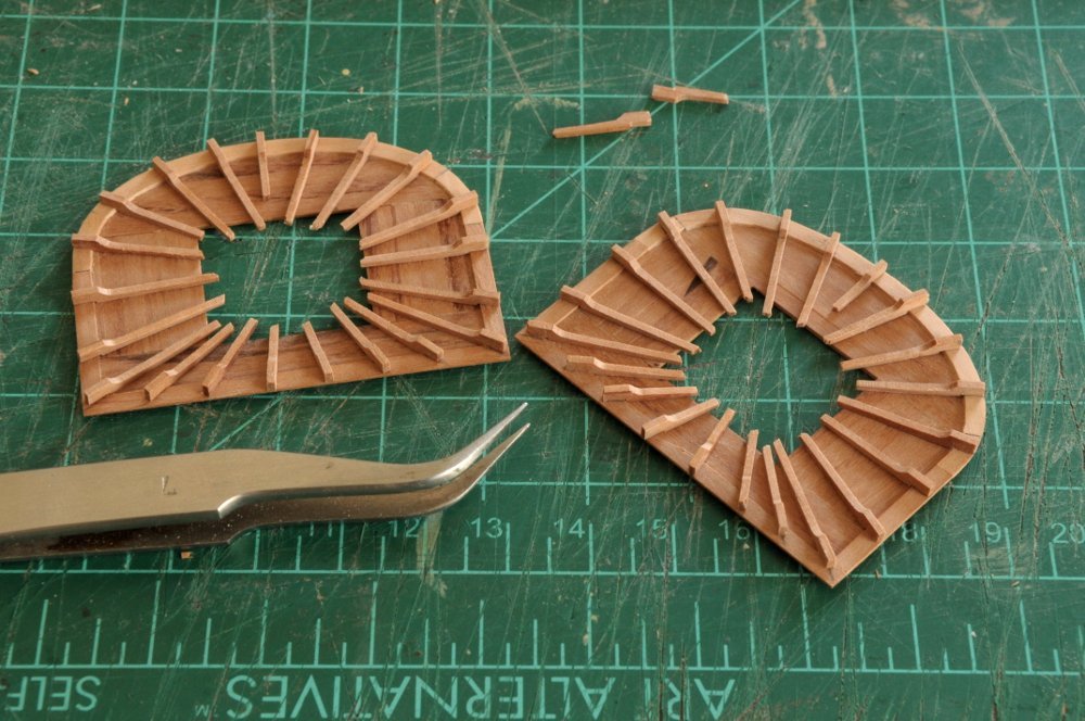
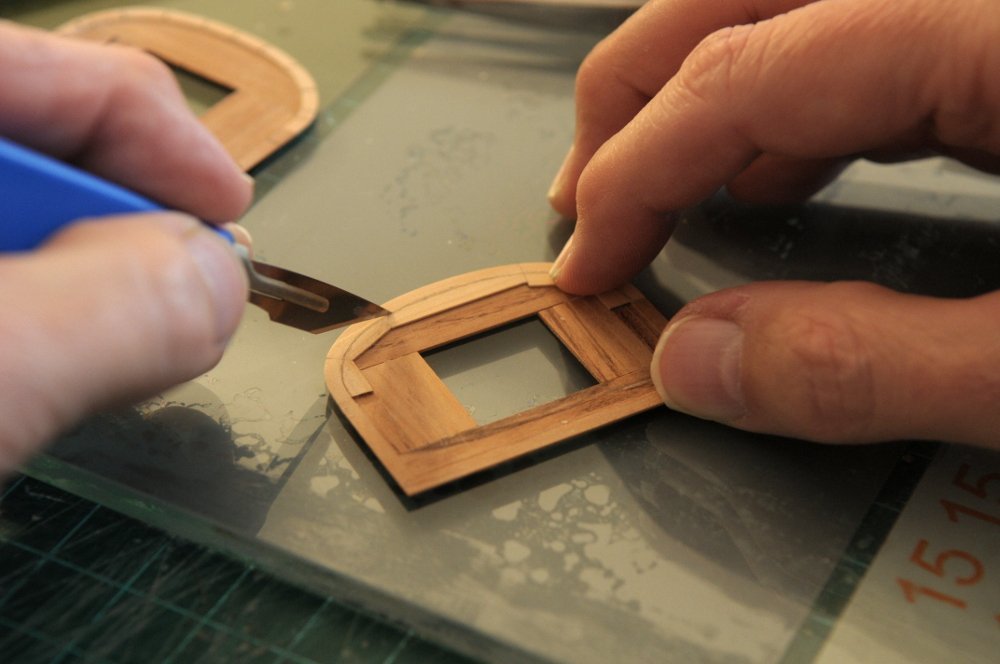
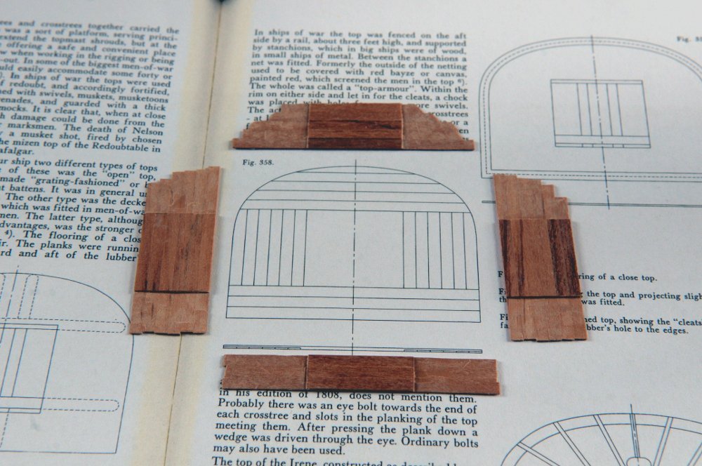
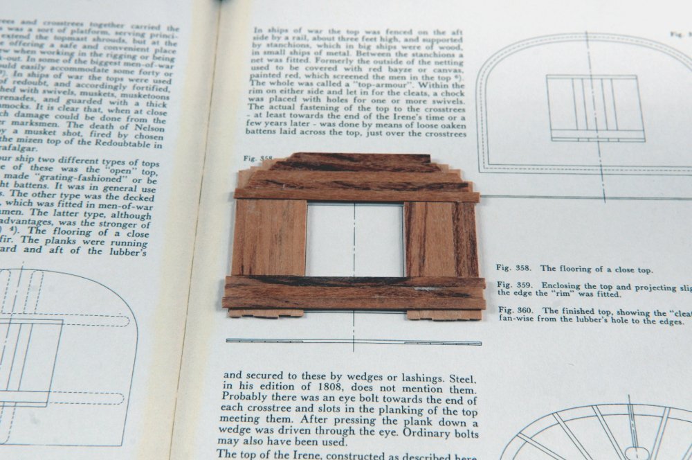
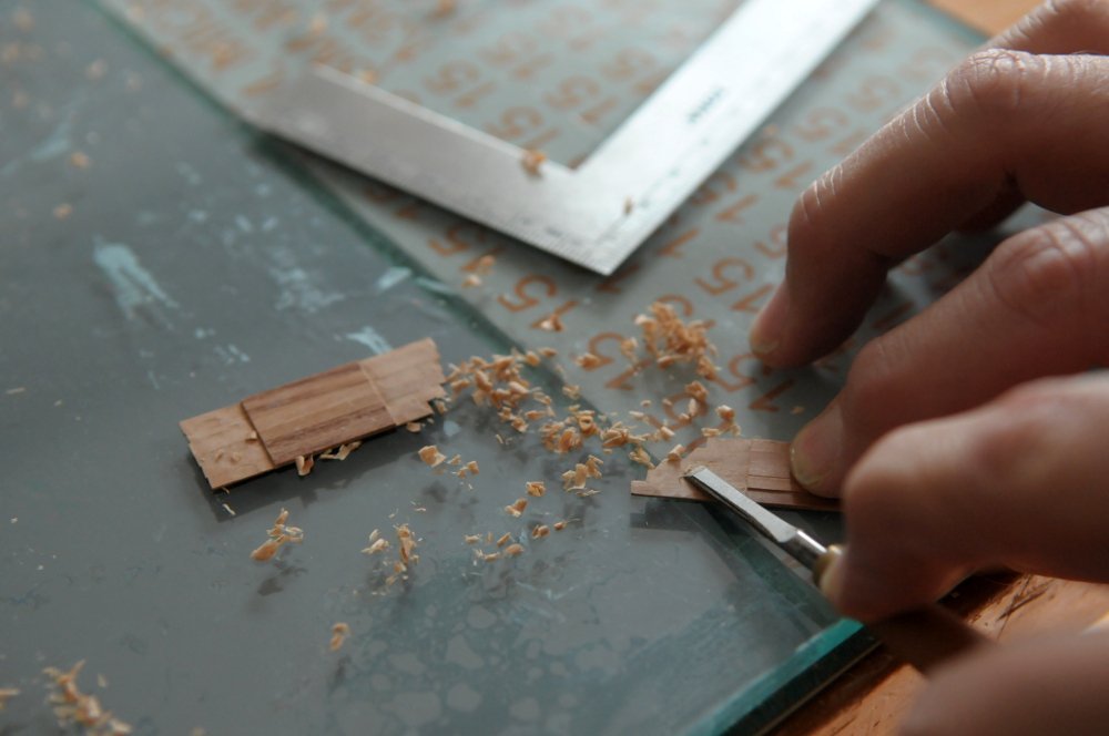
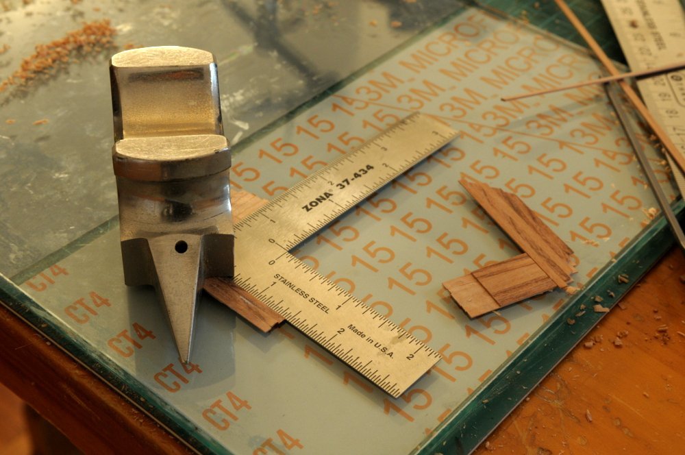
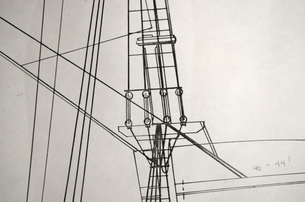
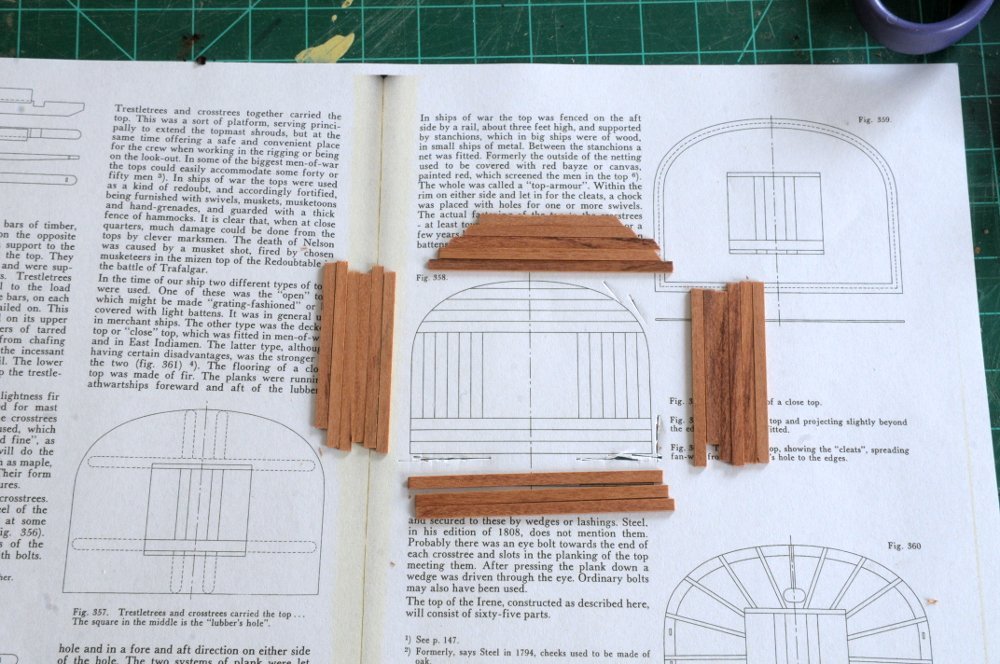
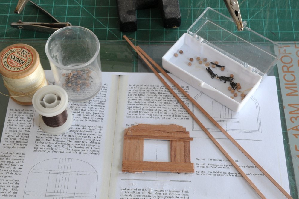
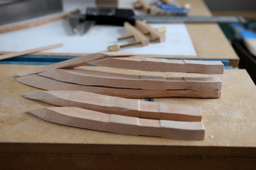
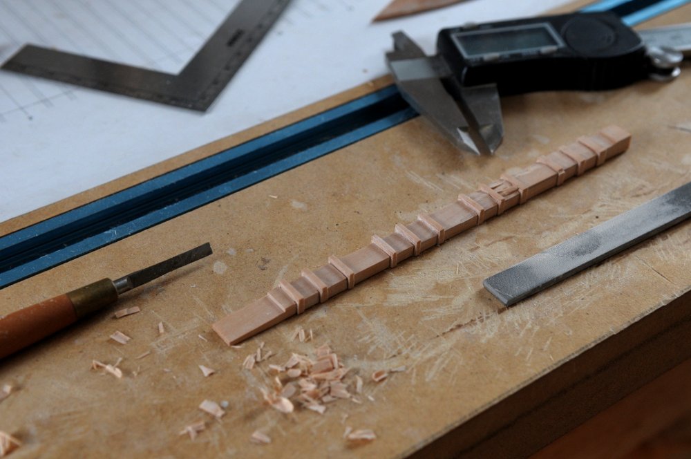
My recent work on Euryalus has actually given me some motivation to do some work on Oneida. I am in the middle of stropping blocks for the carronade tackle, and it's not a task I enjoy. I need 64 blocks, 32 with hooks, and 32 with a hook and loop. (I don't remember the correct term. I'll look it up and edit this later.) There's a photo of a pair in post #645. So I can only do a few before losing patience. I decided to work on the masts; specifically the crosstrees and tops, to break the exasperation of the blocks. Here is Chapelle's spar drawing for Oneida-- Not much detail. It looks like the crosstrees, but without the platform? I'm taking the crosstree dimension, which happens to be 6', and using that to size everything else. Using Petrejus' book on Irene as a guide, I've scaled the top to the size I need, and cut some strips for the platform floor-- These were glued, and now they need to be filed (I can't think of another way I can do this) so they are "let into each other with a half and half dap." Easier said than done considering how thin these are. Here's a shot of the floor planks glued together into the four groups, (not yet "dapped" into each other), my small but growing number of stropped blocks, and the materials going into this work-- Ron
-
Chuck, I think you are a genius. Between you and Chris Watton, kits are light years ahead of where they were ten years ago. Not to mention your ropewalk, innovations in the capstan kits, barrels, lanterns, etc. If ship modeling had mass appeal, you'd be a millionaire. (But maybe you are, with all of your blocks that all of us buy!) Ron
-
HMS Euryalus 1803 by rlb - 1:48 scale
rlb replied to rlb's topic in - Build logs for subjects built 1801 - 1850
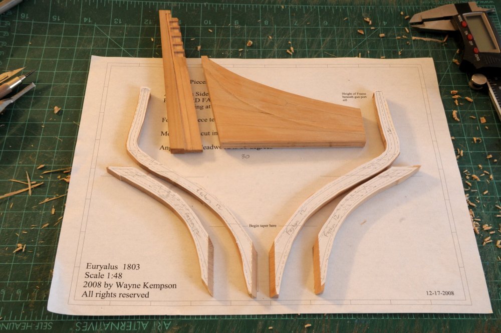
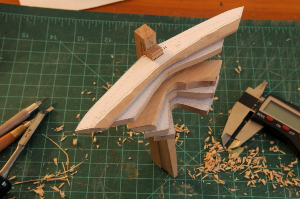
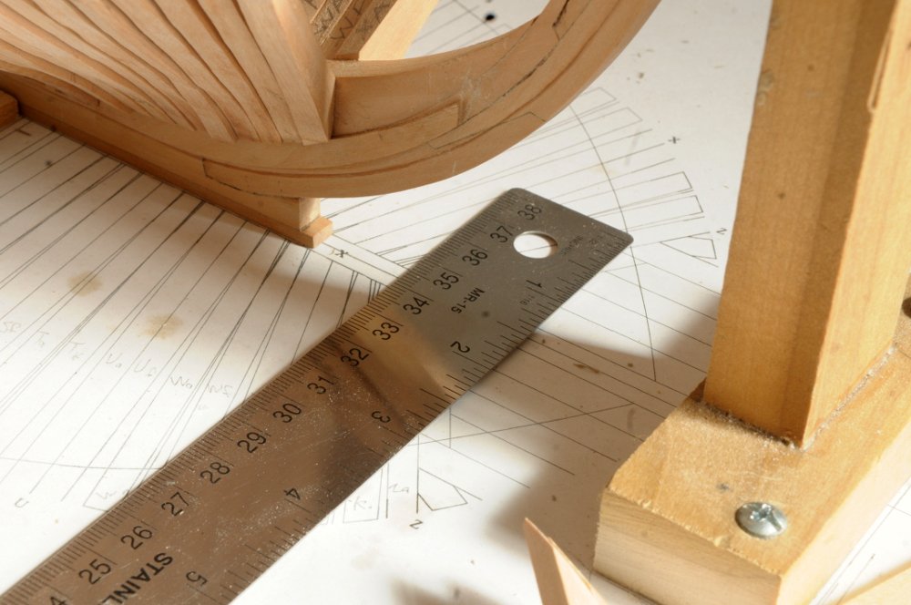
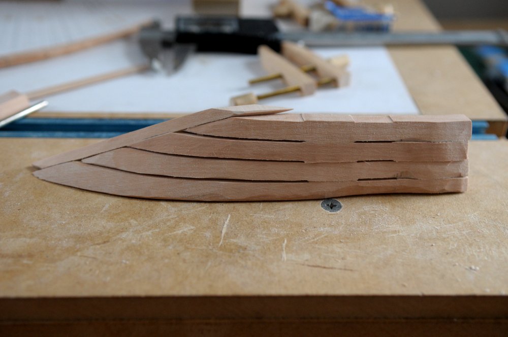
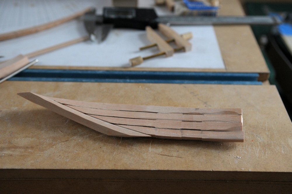
Thanks druxey. I would love to go back in time to visit one of those shipyards! In between sessions of fairing the interior of the bow section, I am preparing the sternpost, deadwood, and transoms. I hadn't cut the rabbet in the sternpost, or tapered the inner post, before gluing them together, so doing that work now is likely more difficult than it needed to be, but many shavings later, it's just about there-- The fashion timbers are cut out, and shaping of the deadwood below the bearding line has begun-- The transoms are cut. Test fitting, and rough shaping is underway. The complex warped shape of the number IV Deck transom is tricky. That's the one without the paper pattern, in the photo. I haven't started the wing transom yet-- Ron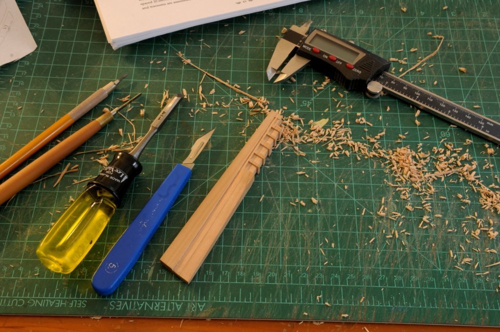
- 122 replies
-
- 19
-
-

-
- Euryalus
- Plank-on-frame
- (and 4 more)
-
Your Winnie looks fabulous, JJ!! Ron
-
HMS Euryalus 1803 by rlb - 1:48 scale
rlb replied to rlb's topic in - Build logs for subjects built 1801 - 1850
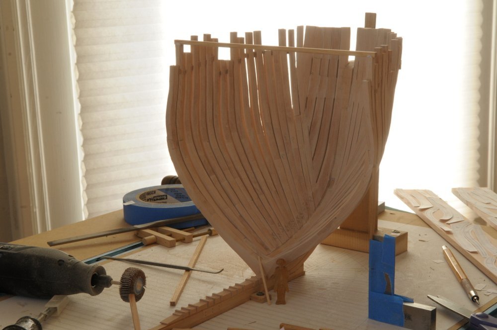
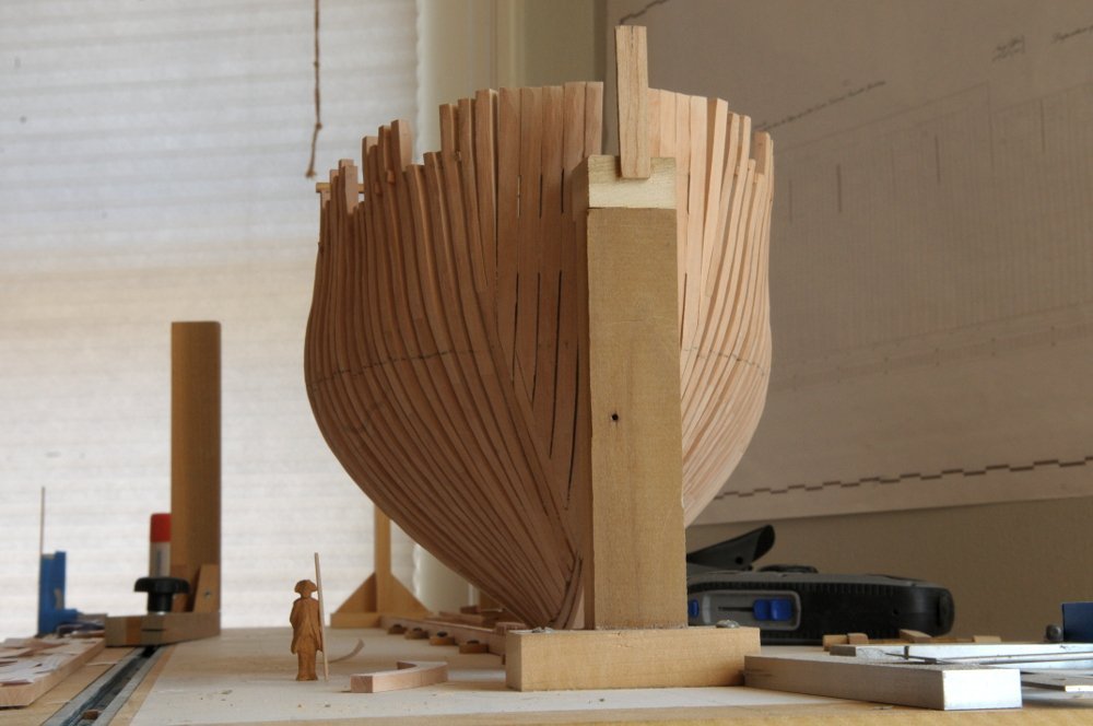
Thanks everyone for the comments, likes, etc.! I adjusted about a quarter of the frames which were slightly out of alignment, ungluing and regluing them. Those starboard hawse timbers that gave me so much trouble needed to be disassembled and adjusted as well. I'm using my bottle of isopropyl alcohol quite a bit, but hopefully now everything is good to go. Fairing the interior has begun-- I'm also starting to cut out the aft cant frames, with the ongoing puzzle of laying out frame pieces as efficiently as I can manage-- Finally for today, a near eye-level view, with a scale figure. He's holding a modern-day 2x4 to help give some idea of the size of the massive timbers that went into these ships-- Ron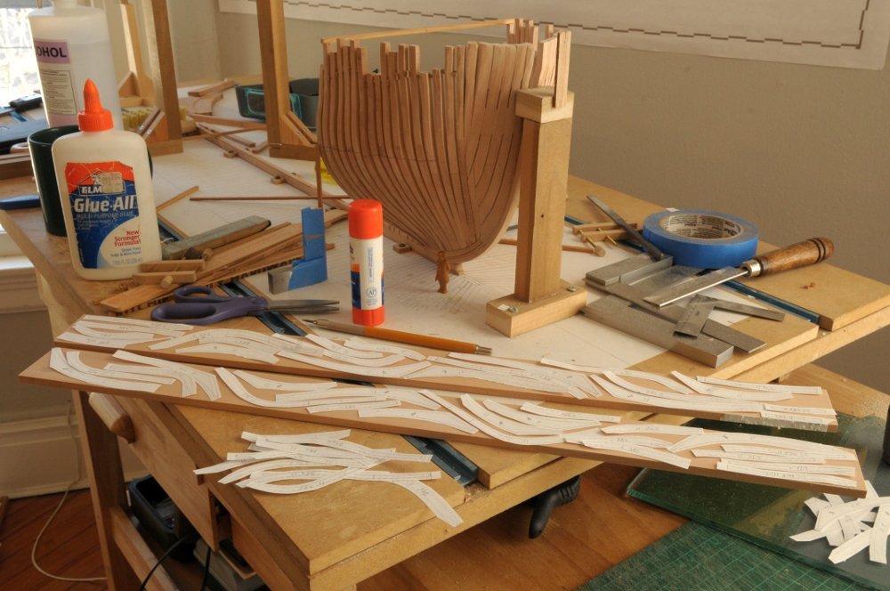
- 122 replies
-
- 19
-
-
-
- Euryalus
- Plank-on-frame
- (and 4 more)
-
Both beautiful models Ben. Nice work! Ron
- 399 replies
-
- 2
-
-
- winchelsea
- Syren Ship Model Company
- (and 1 more)
-
HMS Euryalus 1803 by rlb - 1:48 scale
rlb replied to rlb's topic in - Build logs for subjects built 1801 - 1850
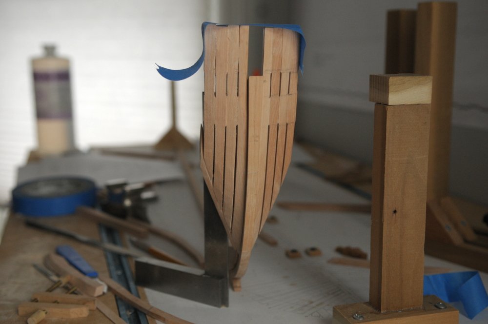
Thanks JohnLea, Ed, botra, druxey and Ben! Yes, once again the learning curve made a fool of me. It won't be the last time! I don't have a problem showing my mistakes, hopefully they give others the idea that we aren't perfect, but we can achieve good results working through the failures. Today was a good day. As before, everything is very lightly glued, and I will have to make adjustments to many of the frames--fine tuning the spacing, mostly-- before committing to permanently gluing them in place (well, with isopropyl nothing is permanent), but I am now confident that I've got the bow under control-- Ron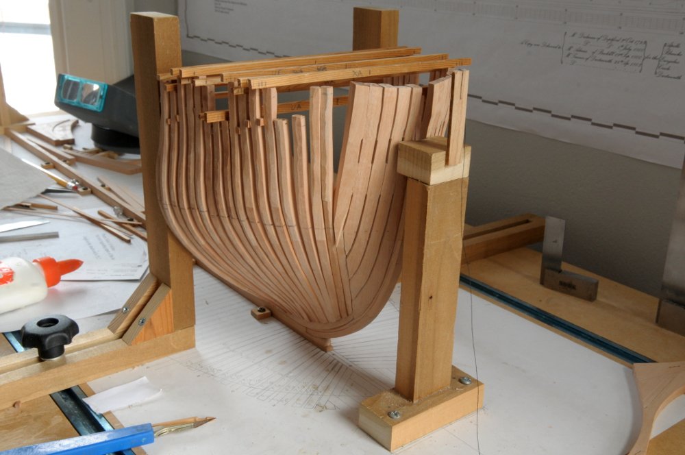
- 122 replies
-
- 15
-
-
-
- Euryalus
- Plank-on-frame
- (and 4 more)
-
HMS Euryalus 1803 by rlb - 1:48 scale
rlb replied to rlb's topic in - Build logs for subjects built 1801 - 1850
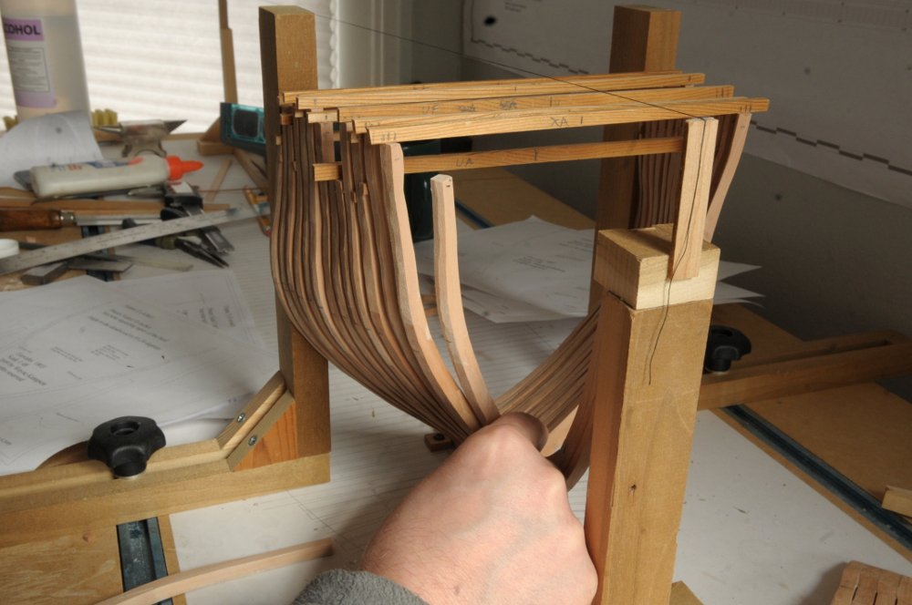
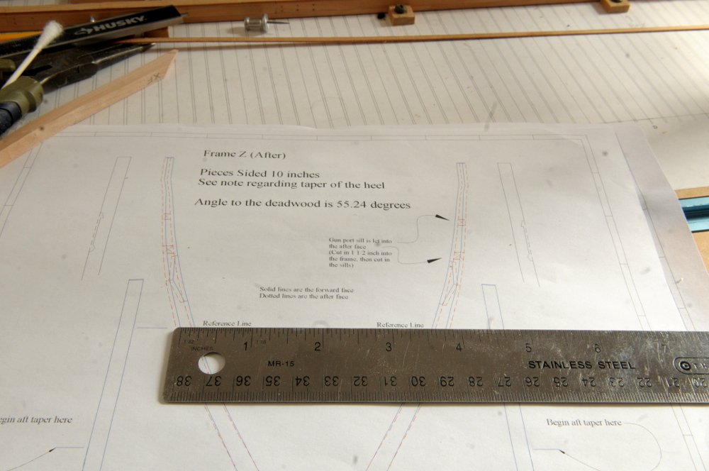
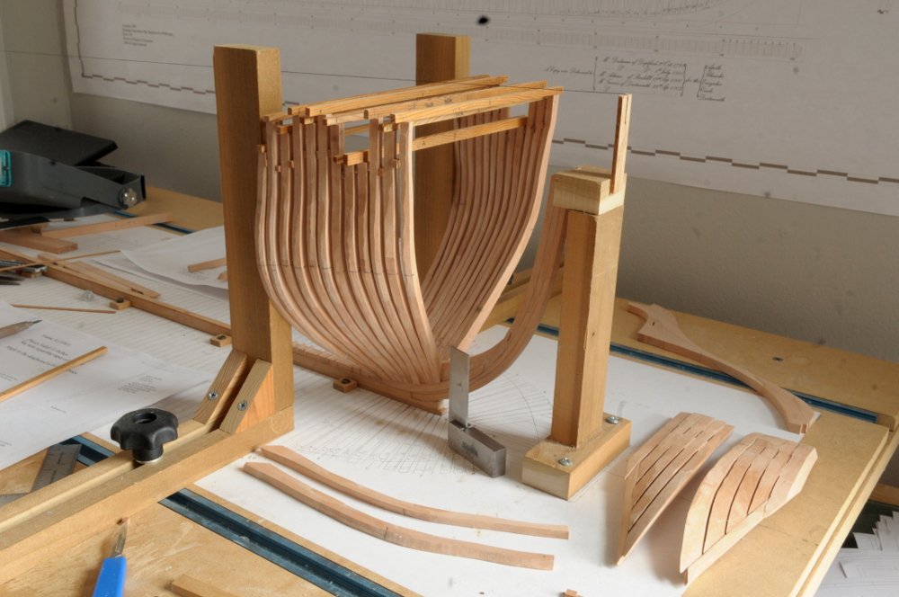
Thanks Allan and botra. After getting all the cant frames cut and glued up, I glued the first rising wood piece in preparation for erecting the first pair of square frames, which will be a starting guide for the cant frames-- That first pair in place, and the cant frames ready to go-- I didn't get far before realizing that I also needed that horizontal piece at the top, to fix the width of each set of cant frames. So I would take a measurement from the frame drawing, and after lightly gluing a pair of cant frames in place, I would check the width with the horizontal cross piece, and if okay, then glue the cross piece in place to hold everything together. This seemed to be going fine-- However, as I moved farther forward, I began noticing that in order to make the right width, my frames needed adjusting to the bottom vertical bevel that joins the deadwood. I thought, well, my initial cutting of that bevel must not have been accurate. Curiously, each frame needed the same adjustment, but I soldiered on. It also started to seem improbable that the bow would narrow enough to meet the hawse timbers-- At this point, when I held up the next frame as I had cut it out, the disparity in width was growing extreme. The frame looked just right when I set it on the frame drawing, but holding it in place, the location compared to the previous frame (which I had adjusted as I thought it needed to be) looked alarming. Something was obviously wrong-- I went back to a frame drawing (I chose Za, the frame next to the hawse timbers) and measured the width on the forward face at the "Reference Line". Just a hair over 3 and 3/4 inches-- Taking this same measurement on the framing guide on the build board the measurement here was almost exactly 3 inches even. How could this be? I knew what was wrong now, though I couldn't understand why, for a while. But it did mean that everything back to the square frames had to be undone. Fortunately (anticipating that I might screw up at some point), I had only very lightly glued everything. It came apart easily-- I now realize WHY taking the width measurement from the frame drawing was incorrect (though it works for the square frames). Painfully obvious in hindsight. I now measure the width at the reference line from the build board and compare it to markings on the lightly positioned frames before gluing the top horizontal piece. I'm just about back to where I was when I learned of my mistake-- Of course, it's all coming together much better now. Previously my one gunport width had been about a 32nd inch or so too wide, and now it's exactly right, which makes sense as the frames haven't splayed out quite so much. There is a slight gap on the bottom of the bevel at the foot of the frames now where they rest on the shelf of the lower apron, because I had taken some wood off in my folly. It will be completely hidden though. Going forward they'll sit the way they are supposed to. It also looks more like the cant frames will turn in enough to meet the hawse timbers. We'll still have to see on that. Ron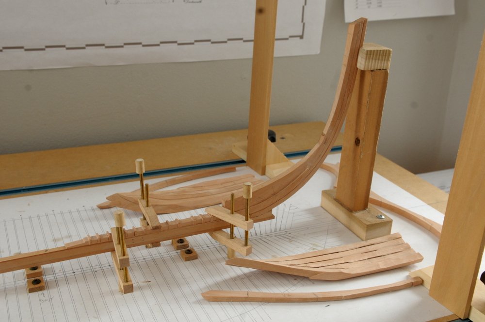
- 122 replies
-
- 15
-
-
- Euryalus
- Plank-on-frame
- (and 4 more)
-
HMS Euryalus 1803 by rlb - 1:48 scale
rlb replied to rlb's topic in - Build logs for subjects built 1801 - 1850
Yes, Allan, that is what I am doing. Thanks for looking in! Ron- 122 replies
-
- 3
-
-
- Euryalus
- Plank-on-frame
- (and 4 more)
-
HMS Euryalus 1803 by rlb - 1:48 scale
rlb replied to rlb's topic in - Build logs for subjects built 1801 - 1850
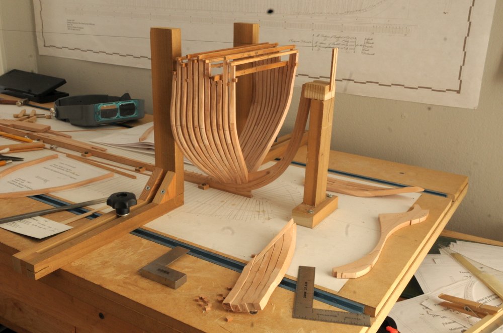
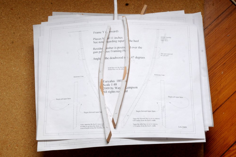
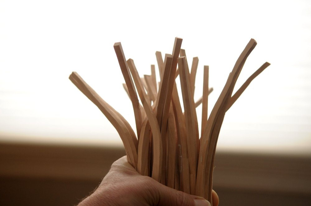
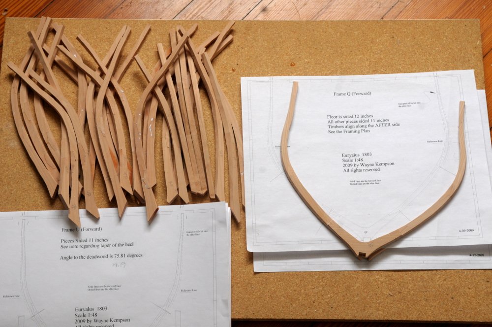
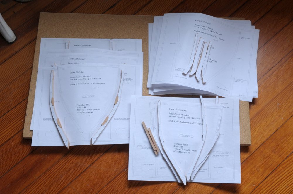
Thanks everyone for looking in, commenting, and liking! It's been a while since my last posting, but I have been spending time in the shipyard. I have been slowly cutting out and gluing up the first full frame pair,Q-(f)orward and (a)ft, and all the rest of the pairs of forward cant frames. Z was already done so that's R through Y (f and a for each). The last two are here. They just happen to be Uf and Sa. I did them mostly in order, but these were a couple of stragglers. Their chocks are cut and ready to glue in-- And the backsides, as the chocks are being glued. The slight angle on the clamping of the clothespins works well with the angle of the chocks since they don't sit square in the frames-- Here's the stack of frames. After gluing the chocks in, each frame was given a rough inner and outer bevel, still leaving them plenty full, to allow for some minor inaccuracy in the shape of the frames, and for fairing. The chocks have been sanded down almost flush. The angle to the deadwood has been sanded in, which is different for almost all of them. Next, the paper needs to be removed from the frames, the frames marked for identification, and then the canted chocks sanded flush with the faces of the frames-- And here is the forwardmost full frame, and the forward cant frames with paper removed (still some bits around some of the chocks); chocks ready to be sanded smooth-- This is an exciting point for me! Soon I'll be ready to put the forward frames on the keel, including the bollard/hawse timbers, and see the bow take shape. Ron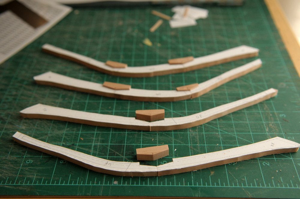
- 122 replies
-
- 16
-
-
- Euryalus
- Plank-on-frame
- (and 4 more)
-
HMS Euryalus 1803 by rlb - 1:48 scale
rlb replied to rlb's topic in - Build logs for subjects built 1801 - 1850
Thanks everyone for your encouragement! It is very appreciated. I carry on. Here are the two sets of bollard/hawse timbers spot glued to the stem. As I previously wrote, the port set seem to be okay, and the starboard set was the trouble. This set looked like it was going to work out-- However, after removing them, and doing some more rough shaping, I discovered that the second hawse timber out was not okay. I unglued it, and cut a new one, very oversized, to replace it-- I spot glued this one in place, and rough shaped the assembly-- Though these are FAR from perfect, and still require plenty of fairing, I pray that they are sufficient; though I will not be surprised to find out farther down the line that they have problems! They will not be permanently glued into place until I have more of the forward framing done. Ron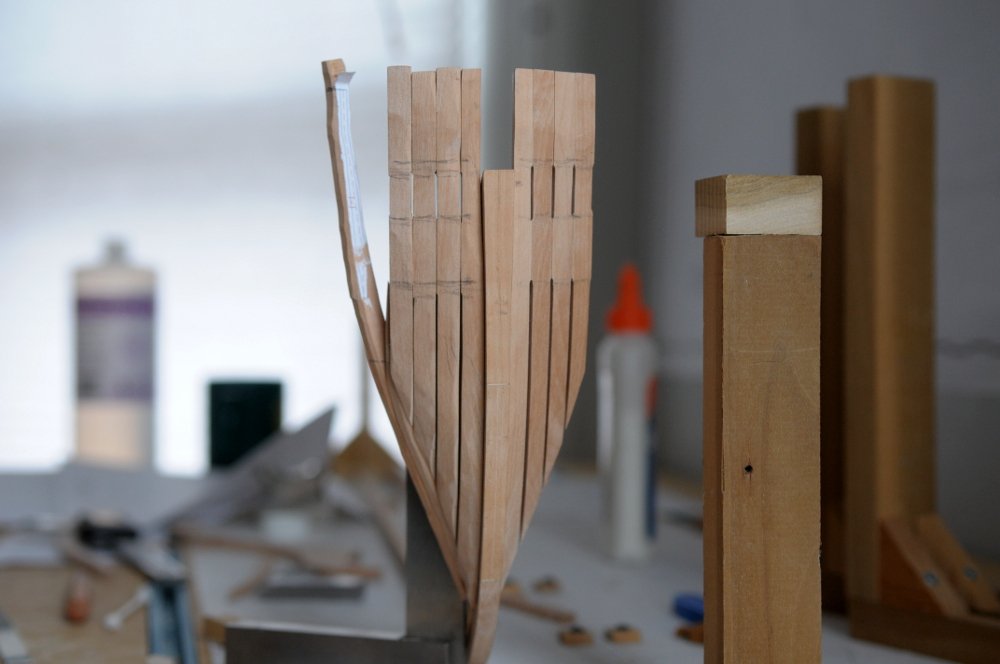
- 122 replies
-
- 21
-
-
- Euryalus
- Plank-on-frame
- (and 4 more)
-
HMS Euryalus 1803 by rlb - 1:48 scale
rlb replied to rlb's topic in - Build logs for subjects built 1801 - 1850
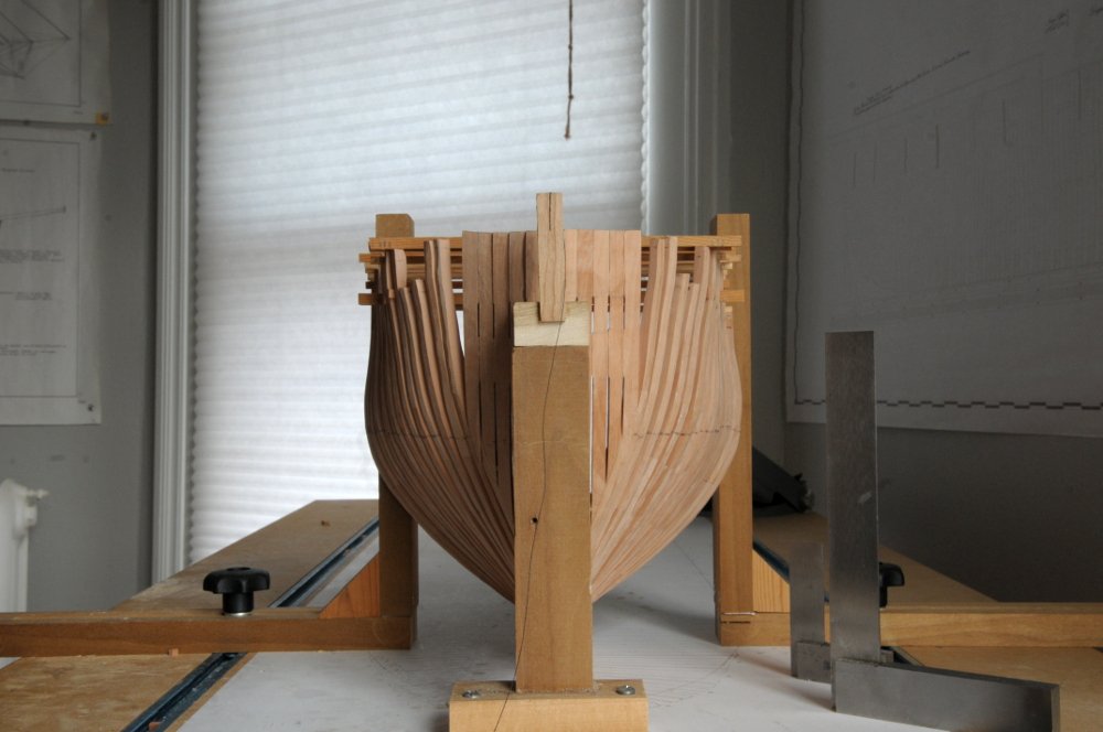
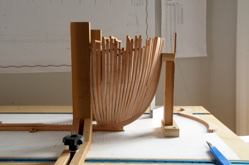
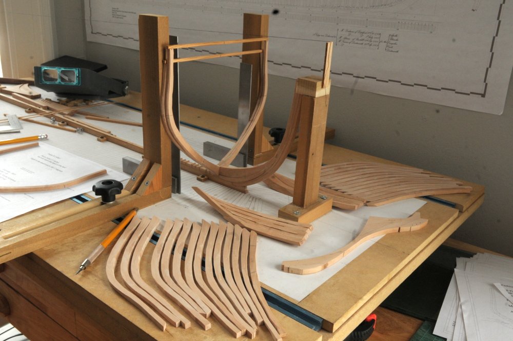
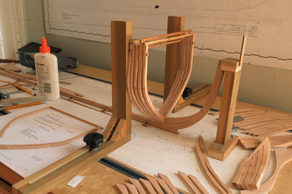
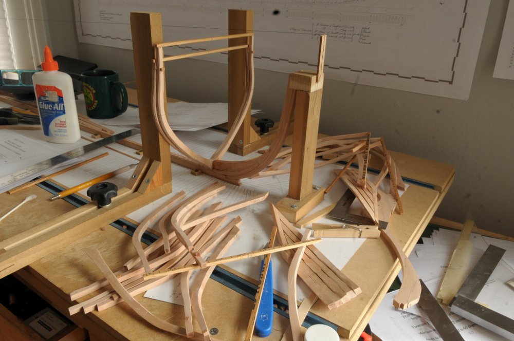
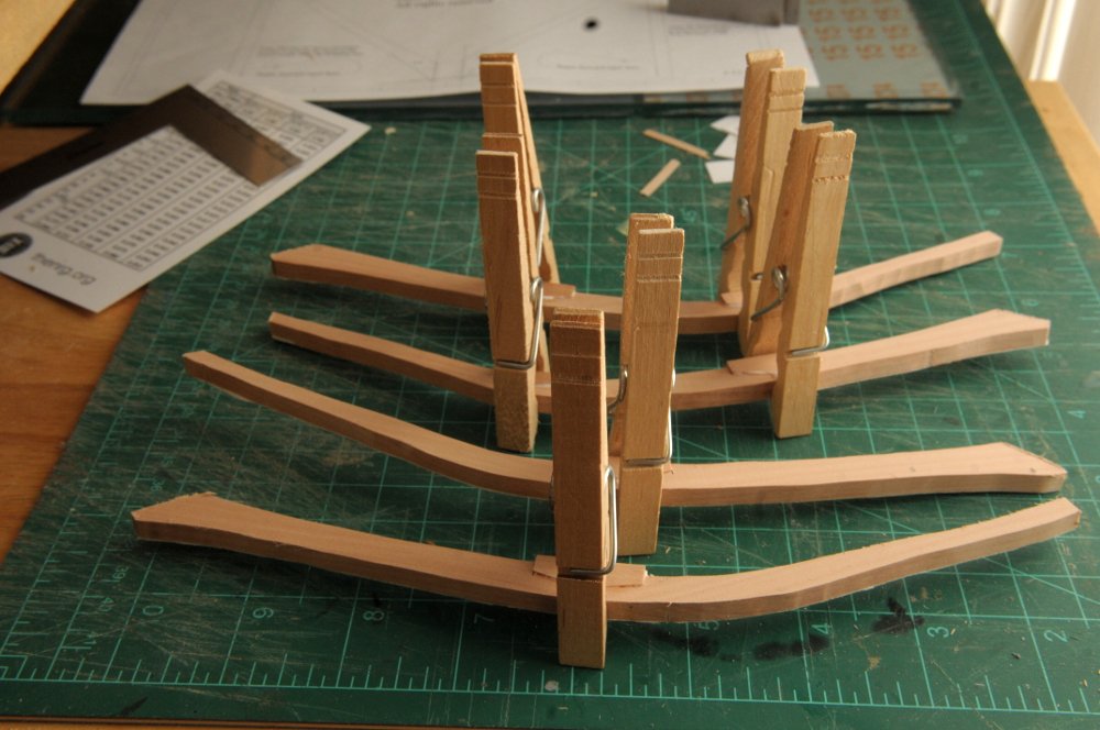
Hello all, It's been since last July that I've done any building on Euryalus. When the 3rd attempt at the bollard and hawse timbers turned out to be a failure, I walked away, and I've only just in the last week or so had the motivation to try again. So here I am-- As far as I can tell, the 2nd attempt at the port bollard/hawse timbers was okay. I was lucky I think. It's the starboard ones that have given me fits. Here is a fourth batch cut out, roughly shaped, and stacked on the board. During fitting, they seem good. I am doing a first pass at sanding the partial gaps in them. I'm not very confident yet with my Byrne's saw skill, so I'm still doing the gaps by hand. I'm also starting to cut out the rising wood pieces. I tried initially to use my rotary tool as a milling machine, to cut the notches, but the vertical adjustment is too imprecise and difficult get a consistent result with, so I'm doing the frame notches by hand, using a saw, small chisel, and file. I've broken one corner, but I'll repair it and any other that may get "chipped" at some point-- Another task is slowly working on cutting out and assembling the frames. First rough cut the pieces, then cut and chisel out the chock notches, glue up the frames without chocks, then shape and glue in the chocks. I have all the forward cant frames at various stages of assembly-- Ron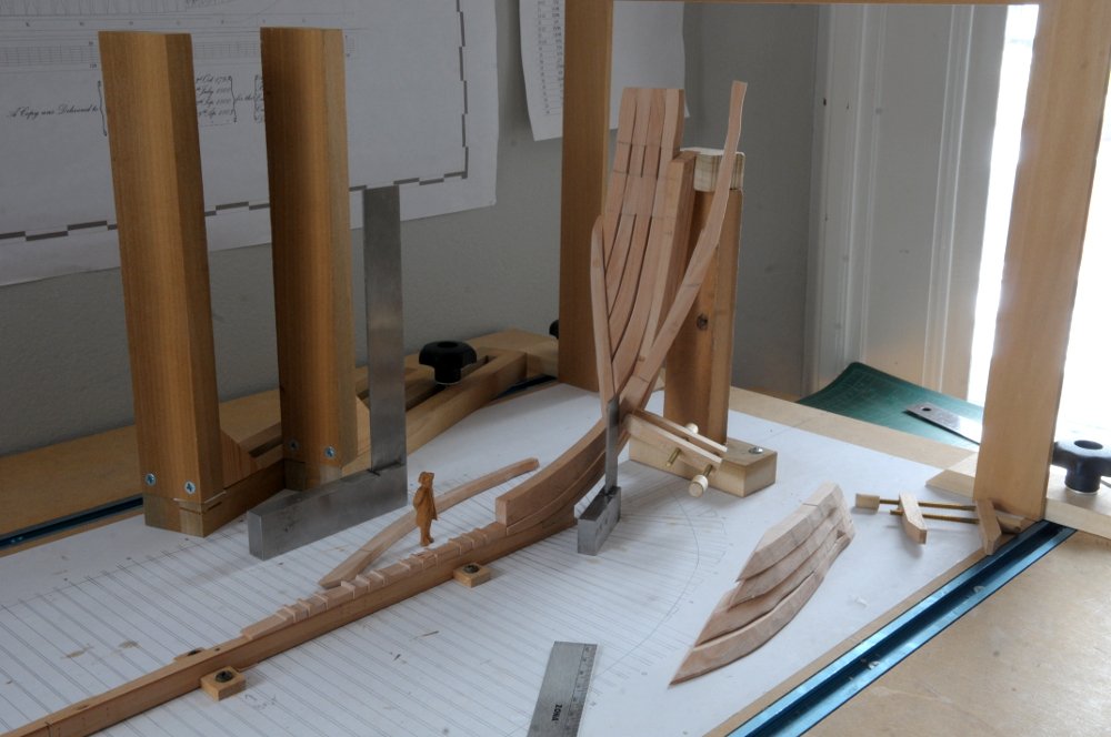
- 122 replies
-
- 15
-
-
- Euryalus
- Plank-on-frame
- (and 4 more)

