
MORE HANDBOOKS ARE ON THEIR WAY! We will let you know when they get here.
×


rlb
-
Posts
655 -
Joined
-
Last visited
Content Type
Profiles
Forums
Gallery
Events
Everything posted by rlb
-
 Mike, I understand the rustiness of starting again. My own modeling has been periods of good work, then long periods (sometimes years) of inactivity. It takes a lot to get back into the right mental frame to work, especially when you are working on something that requires checking sources, calculating things, planning the order of tasks, not to mention the concentration of doing the actual hand (or machine) work. When I start back up sometimes I can only work for 10 or 15 minutes at a time, for a few days, at least, until I build up my modeling stamina! Good luck on your progress! Ron
- 967 replies
-
- 4
-

-
- hahn
- oliver cromwell
- (and 1 more)
-
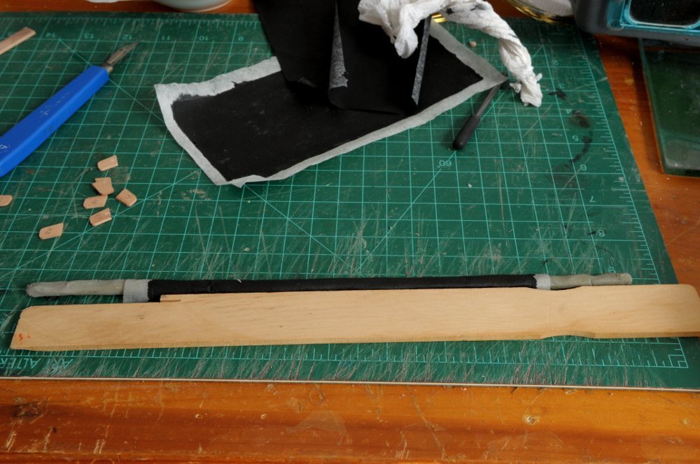
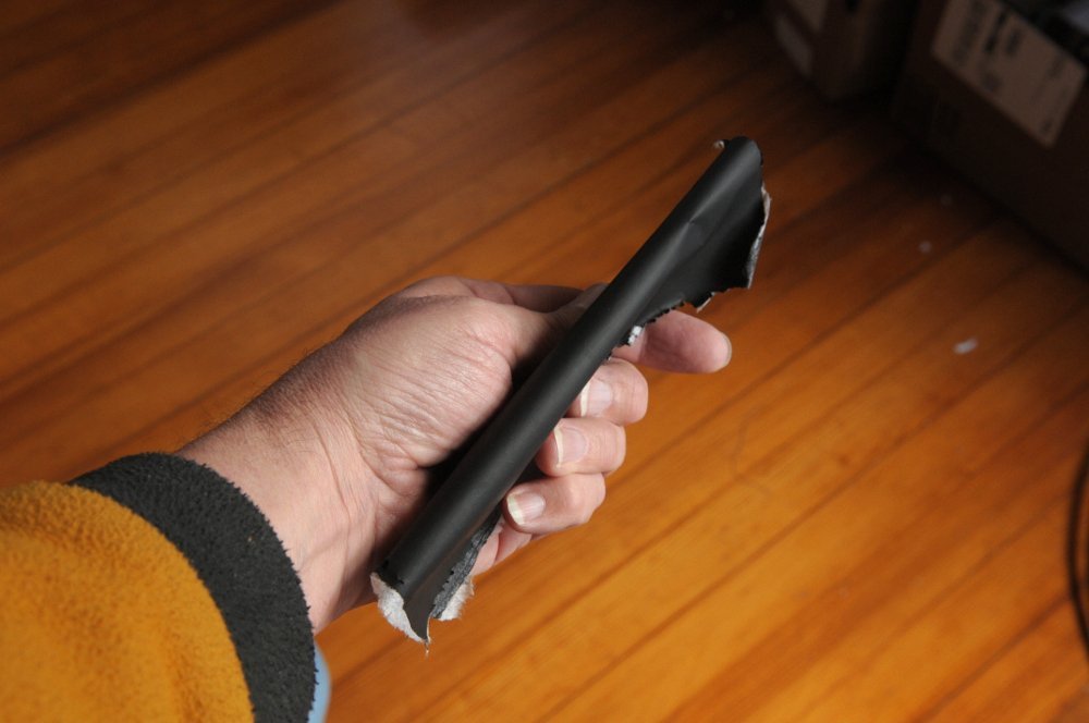
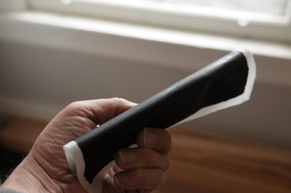
Continuing on. I'm going to try using clay to stand in for the hammocks. My plan is to wet the Silkspan, and wrap the clay. Hopefully when it dries it will shrink a little and take on the bumps in the clay. We shall see. First test is to size the clay filler, and determine the right width to cut the Silkspan-- I folded this piece over the clay, and held the ends down just to try and get some idea how it will work, and look. It hasn't been wetted, and it's also the thicker Silkpan, which I don't intend to use. But I can waste it to test, and determine the width piece that I need. I think I can trim 1/4 inch of the width of this piece-- I'm also ready to start locating the end caps and cranes on the cap rail. After epoxying a pin in each end cap, I located them on the ship, drilled holes and dry fit them-- Incidentally, I ended up narrowing each cap a bit. These looked okay in place, so I drilled more holes in the cap rail and tested the 7 aft starboard hammock cranes in place-- I discovered that some of the blackening on the cranes had either not taken, or had flaked off, so they will need to be re-blackened. I also see that the end caps need some adjustment of the top curve. The two at the entry steps are not uniform. When I narrowed the end caps I also adjusted the angle/curve of the tops, and apparently I "fixed" some more than others. The angles on the iron cranes will need fine tuning as well, once they are glued on. All for now. Ron
-
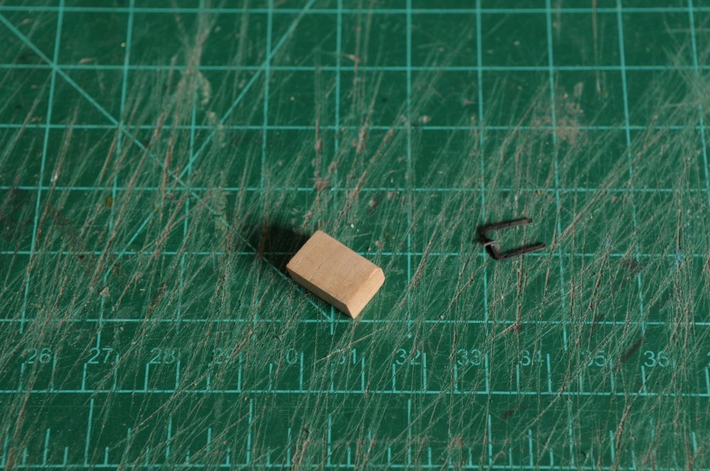
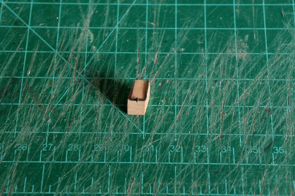
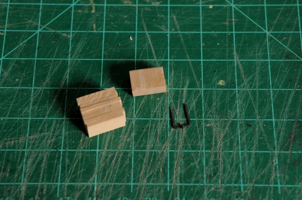
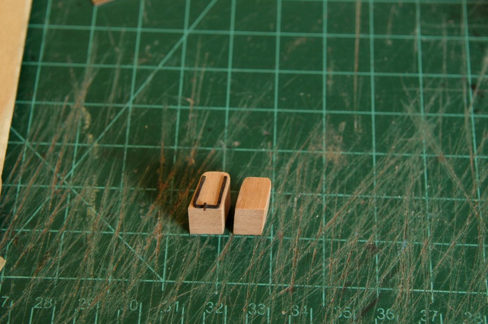
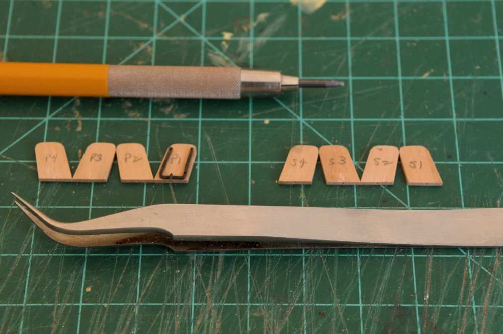
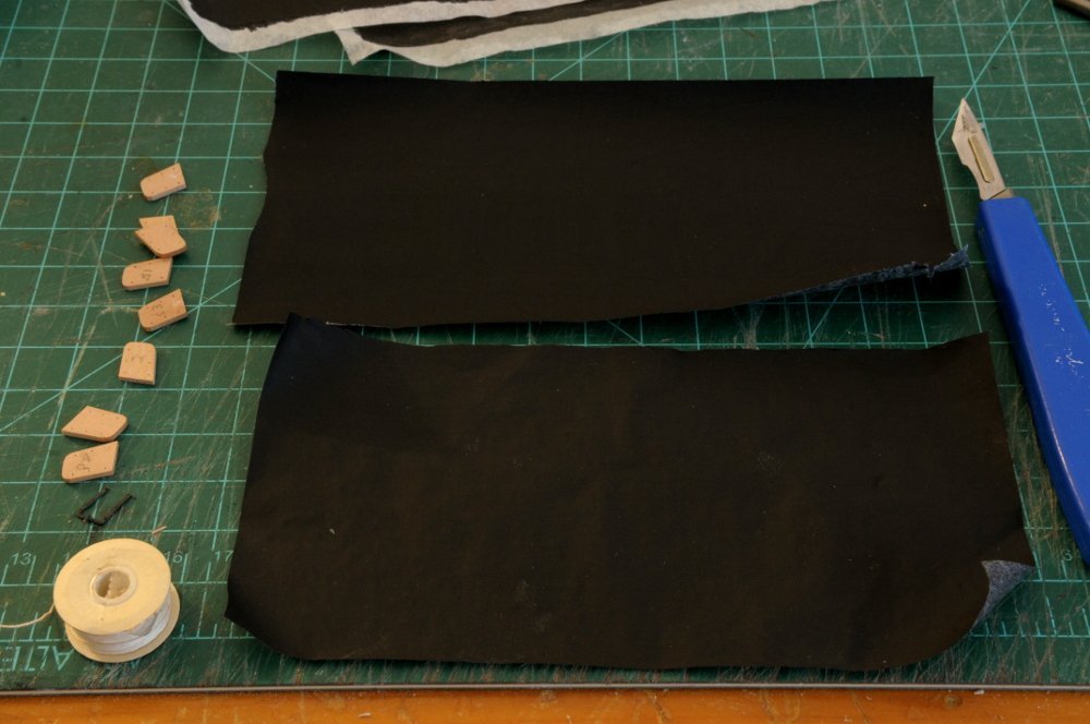
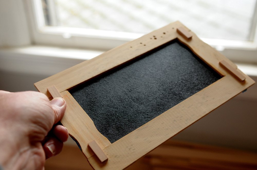
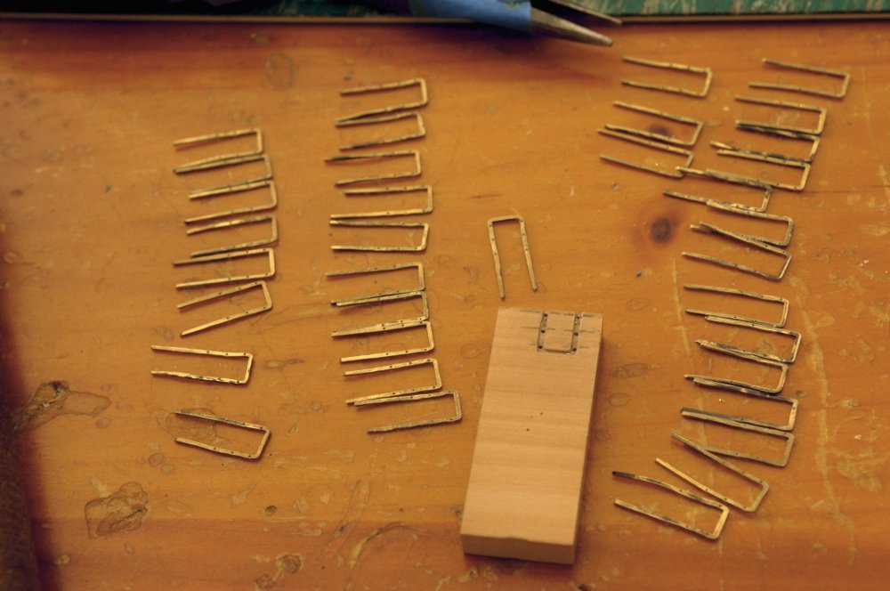
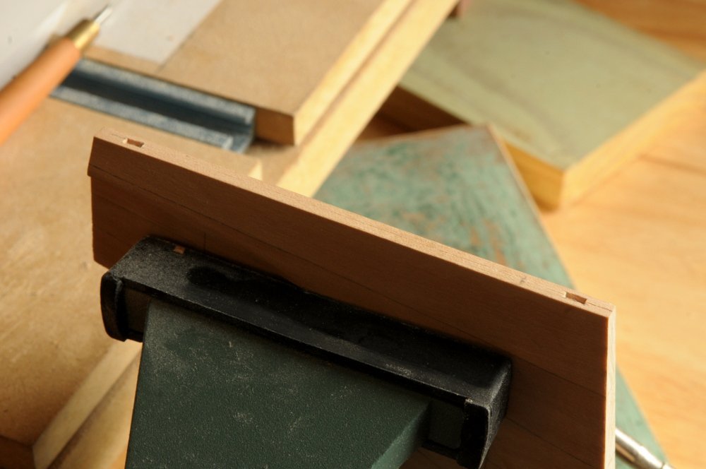
Experiments with Silkspan continue. After applying another couple of coats to the example in the previous post, I decided to try the "thin" Silkspan; the above post used the "medium" variety. There is a big difference in thickness. After wetting and taping a piece to my frame (and letting it dry), this time I applied acrylic matte medium to both sides of the Silkspan, hoping that this would fill in the fibers, so that I wouldn't need as many coats of black paint to make it opaque-- This seemed to work, and after three (I think) coats of black, I had a nice smooth, opaque surface- While coats of paint were drying, I glued eight thin pieces of wood into a block, to shape into the end caps for the hammocks-- I decided that I would follow the angle of the bulwarks, inner and outer, with the hammock cranes and the end pieces-- However, my shaping had reduced the "block" too much. It was too definitely too short, and too narrow for comfort, so I glued another set together- These should work-- I separated them, and because some had slight marks from prying them apart I sorted and numbered them to put the "bad" sides inward where they would be covered by the hammock cloth and not seen. I drilled holes in the bottom for pins-- I marked and drilled the holes for the six lines in the end caps. Here also are two sheets of painted "thin" Silkspan, which I will use-- I'll now experiment with how to shape and place the hammock cloth within the cranes, and epoxy the cranes and end pieces to the ship. I'll probably need another sheet of Silkspan also. All for now, Ron
-
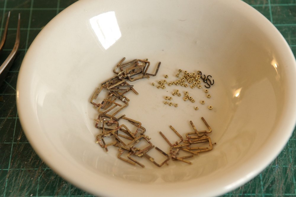
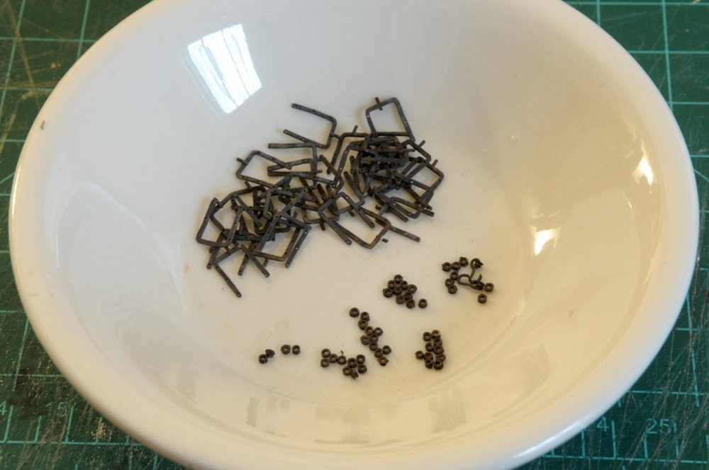
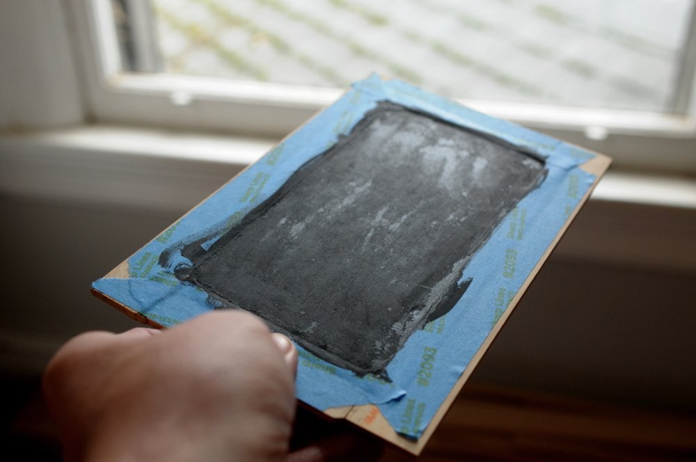
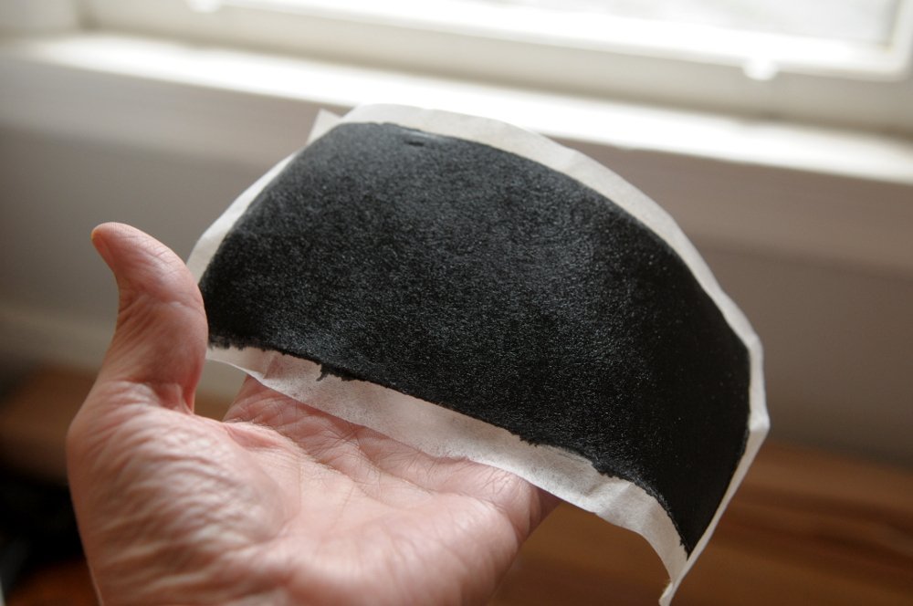
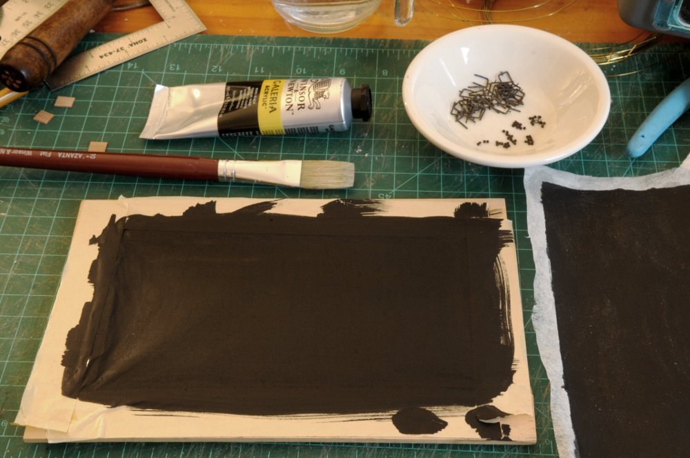
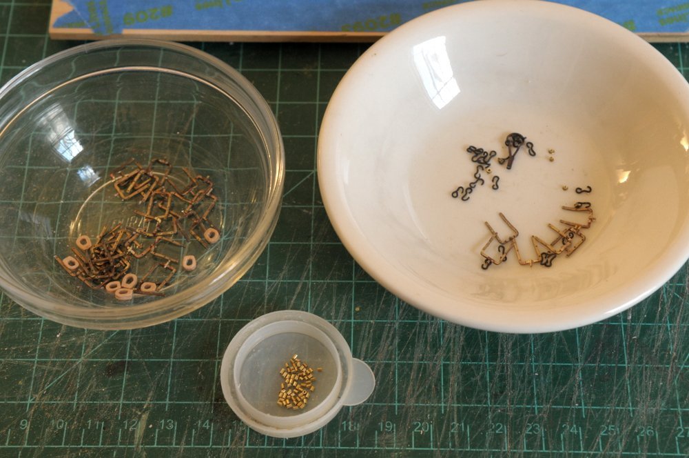
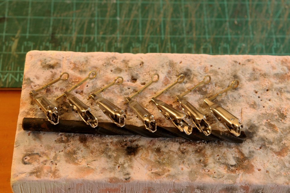
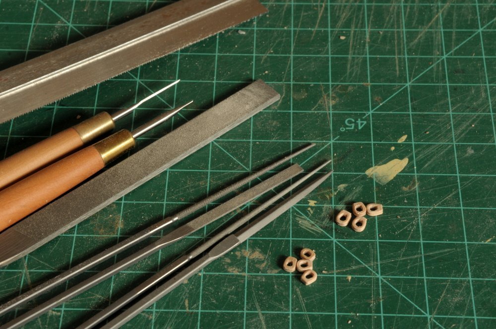
I continued work on the hammock cranes, and also punched out a number of thimbles. I'm happy to report that my success rate improved greatly, and I only lost one!! These are now ready to blacken-- After blackening-- The thimbles are in groups of ten, plus four. Fifty-four in all. Hopefully enough, though I may need a few that are bigger. I don't know. On to the Silkspan. After putting a second diluted coat on the piece, it was just as transparent as before when backlit--not so much when viewed normally. So I painted a coat on undiluted-- It was pretty opaque, but there were now brushmarks that would be out of scale. It was also uneven coverage. Most of it was smooth (though with some brushmarks), but some areas still showed the fibrous texture of the Silkspan. All in all not a satisfactory result. I also wasn't sure it had enough sheen to look like oiled or tarred cloth. So I tried painting the back side with Tung Oil finish to see how that looked-- It really accentuated the texture. Not at all to scale. What was worse, the Tung Oil seeped through the thin areas on the "front" side, making that side kind of a mess-- Off the frame this is the back side-- And this the front-- When doubled over, similarly to how it will be seen on the model, the sheen of the painted (front) side may be okay. Maybe less than actual oiled cloth (I'm not even sure!), but as is typical with scale models, gloss looks better if it's toned down-- So I will try another piece. I'll build up the layers with diluted paint, until the fiber is filled in evenly without brush marks. I'm also using a much larger brush. I don't feel like I'm "scrubbing" into the material nearly as much. After the second coat it was much more opaque than the first attempt, even though I don't think the paint was any thicker. This is coat number three. I'll need at least one more-- All for now, Ron
-
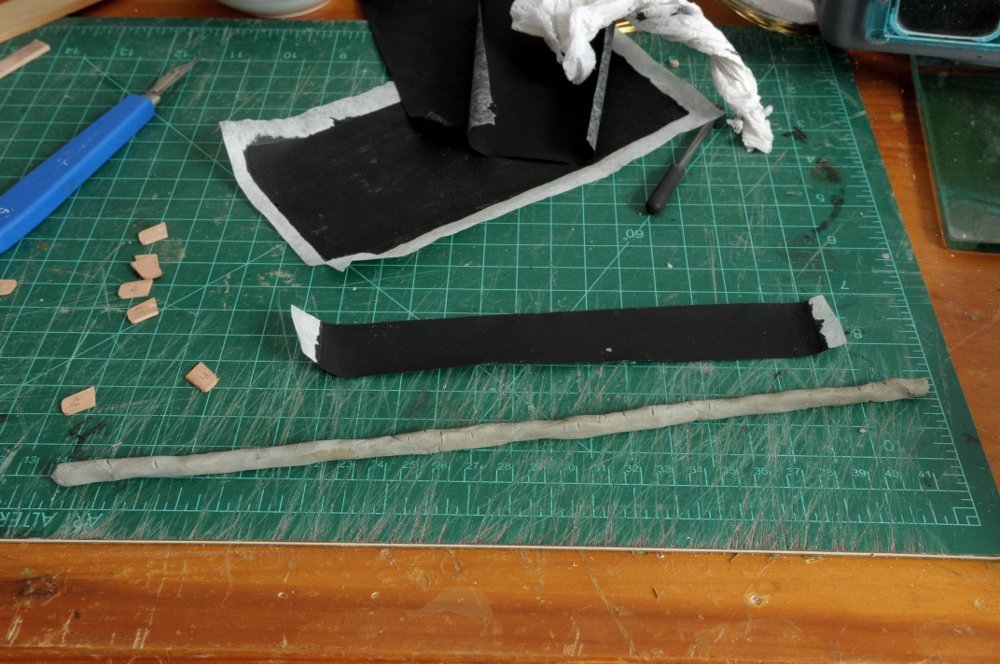
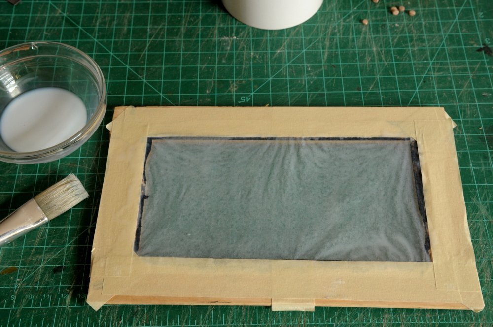
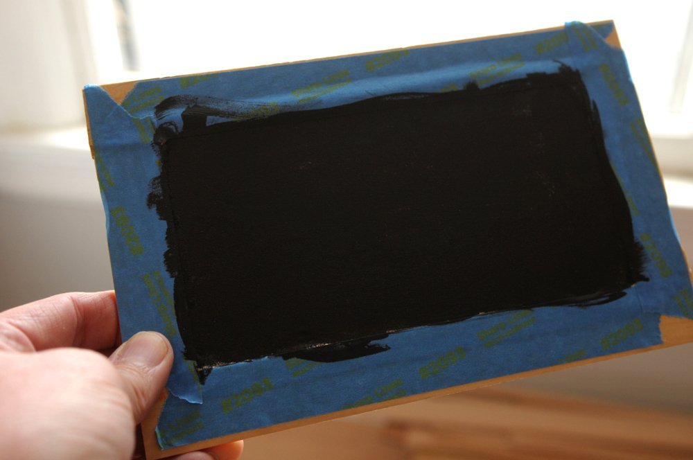
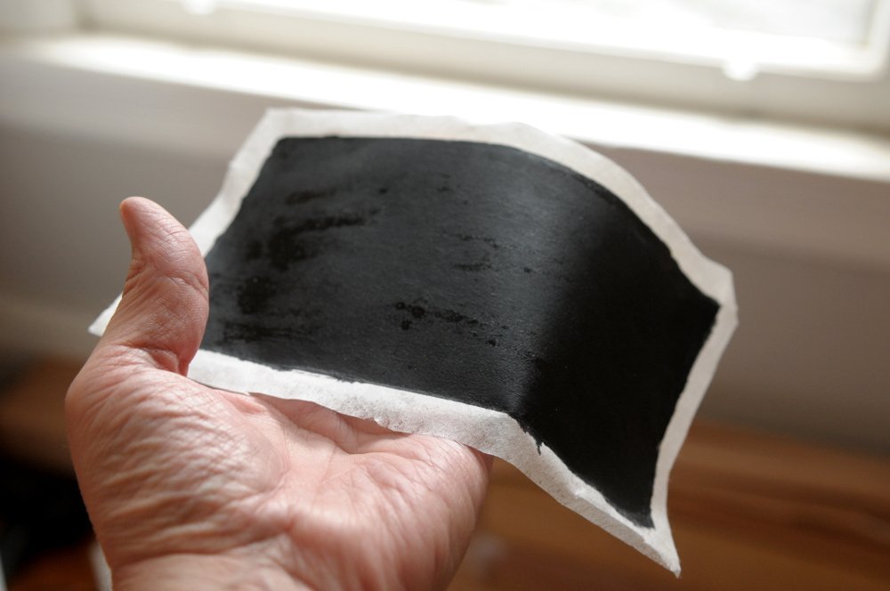
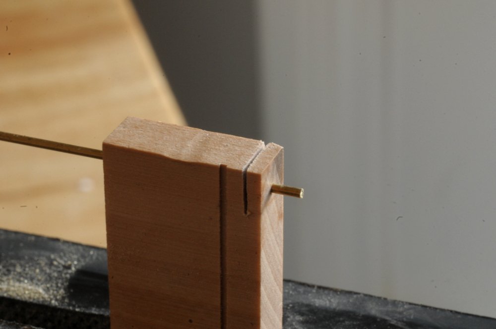
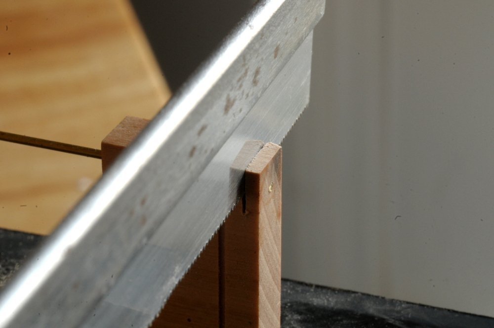
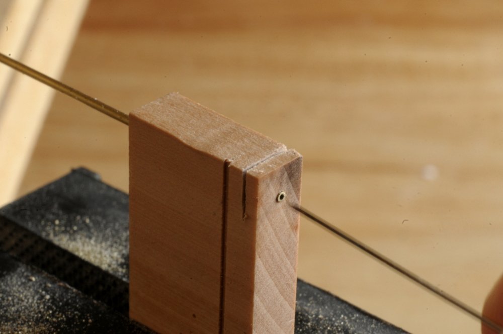
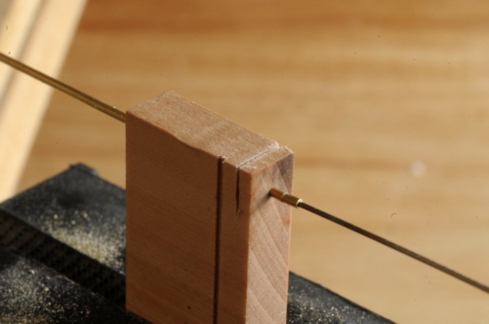
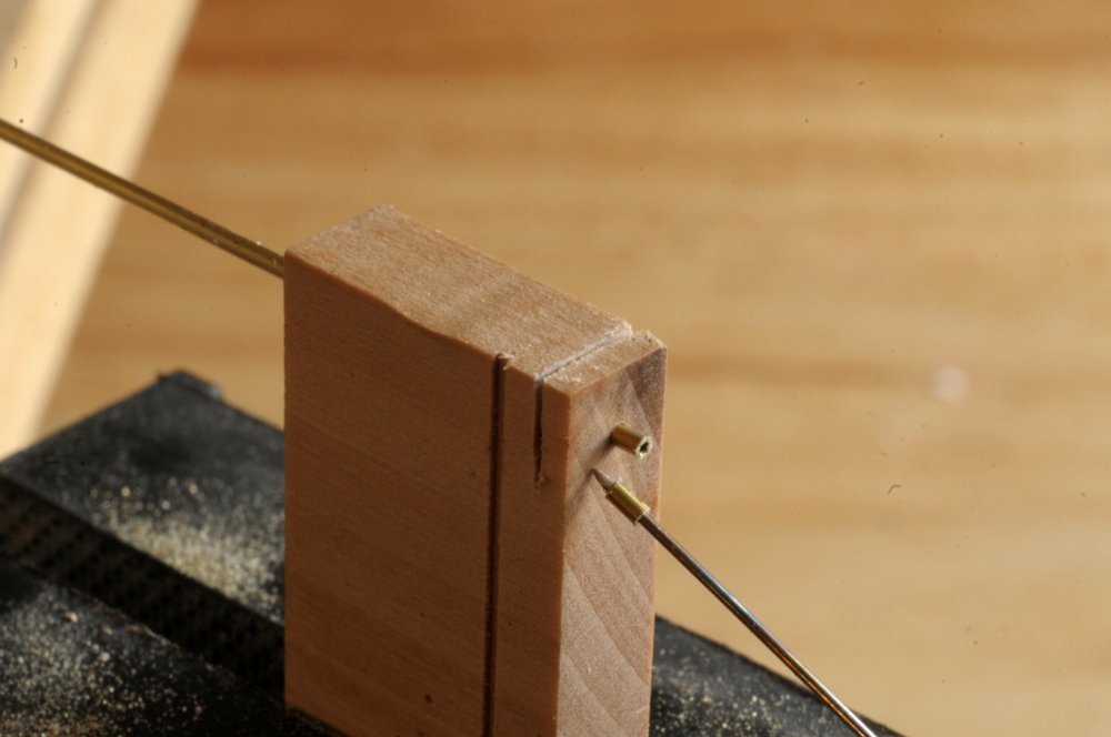
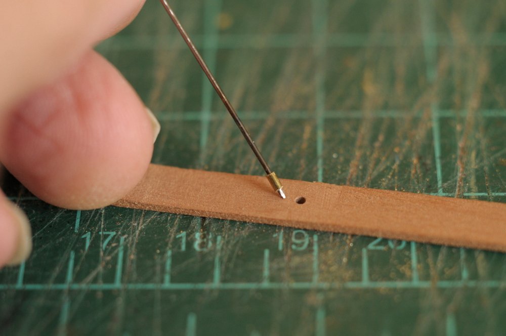
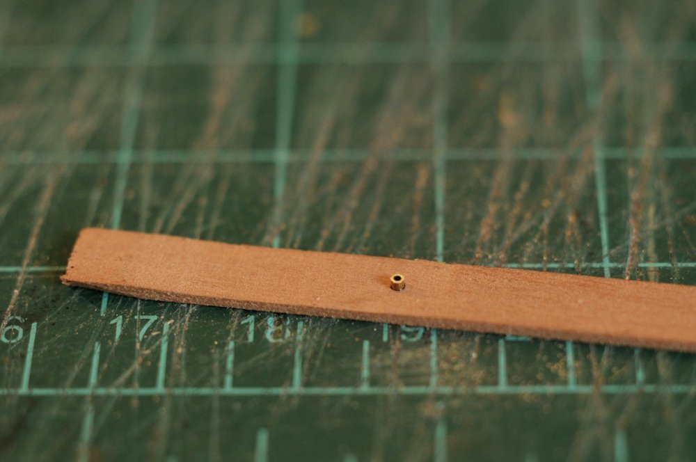
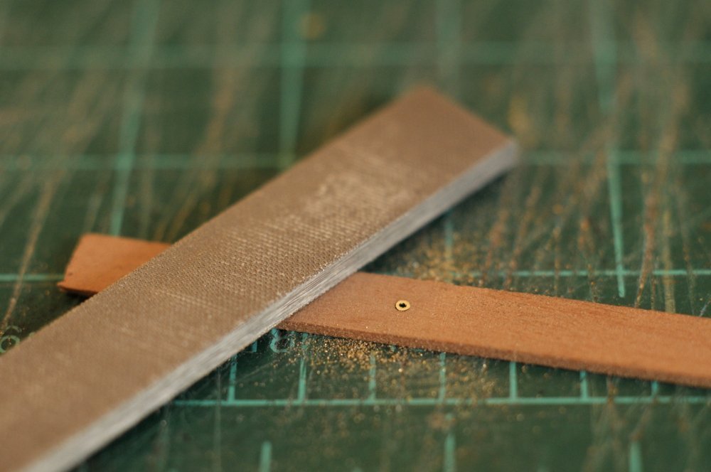
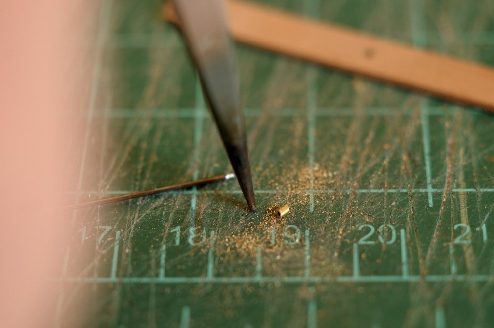
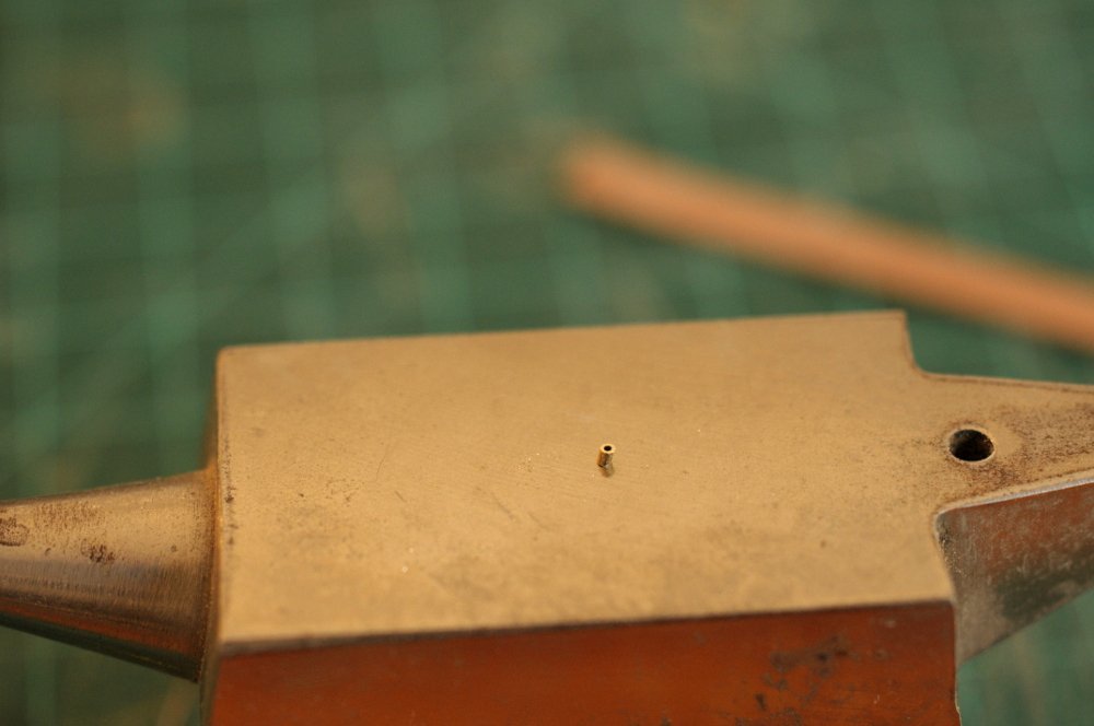
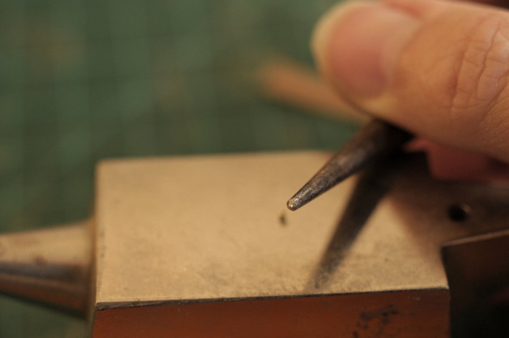
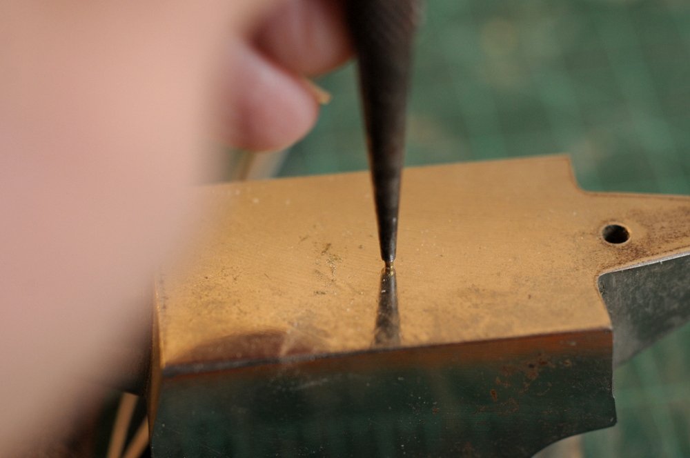
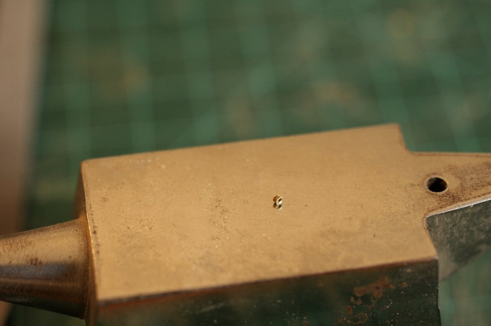
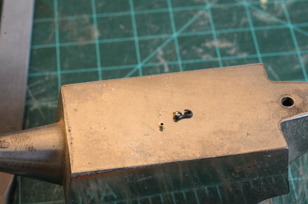
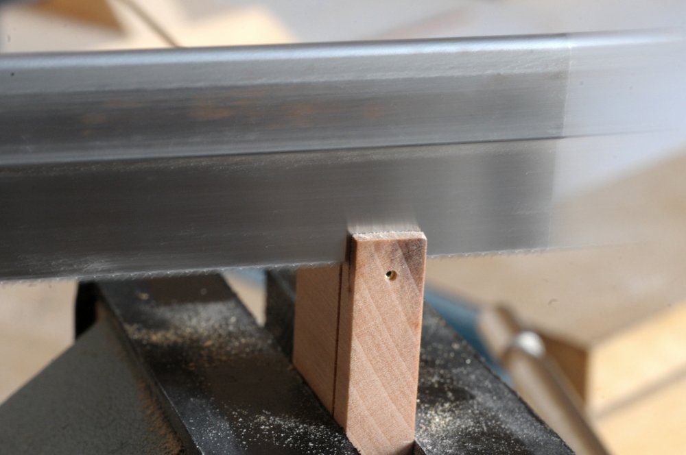
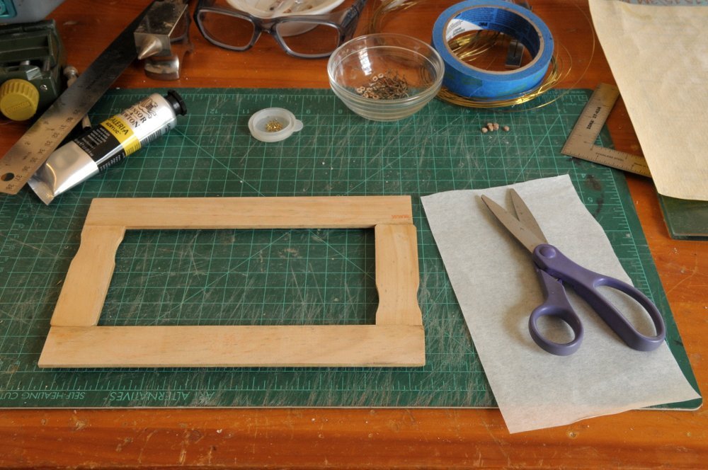
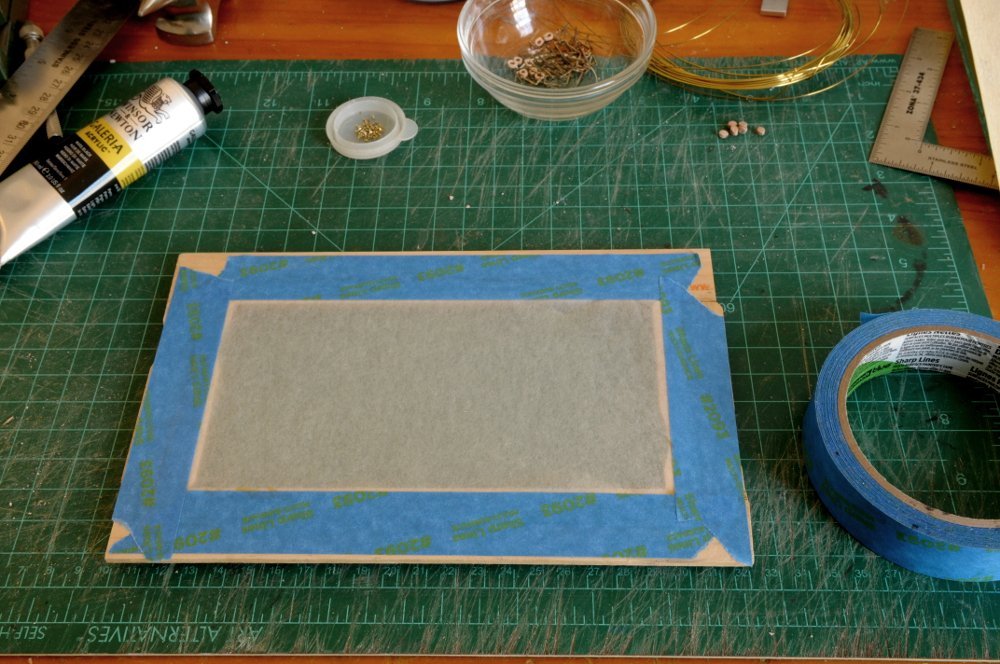
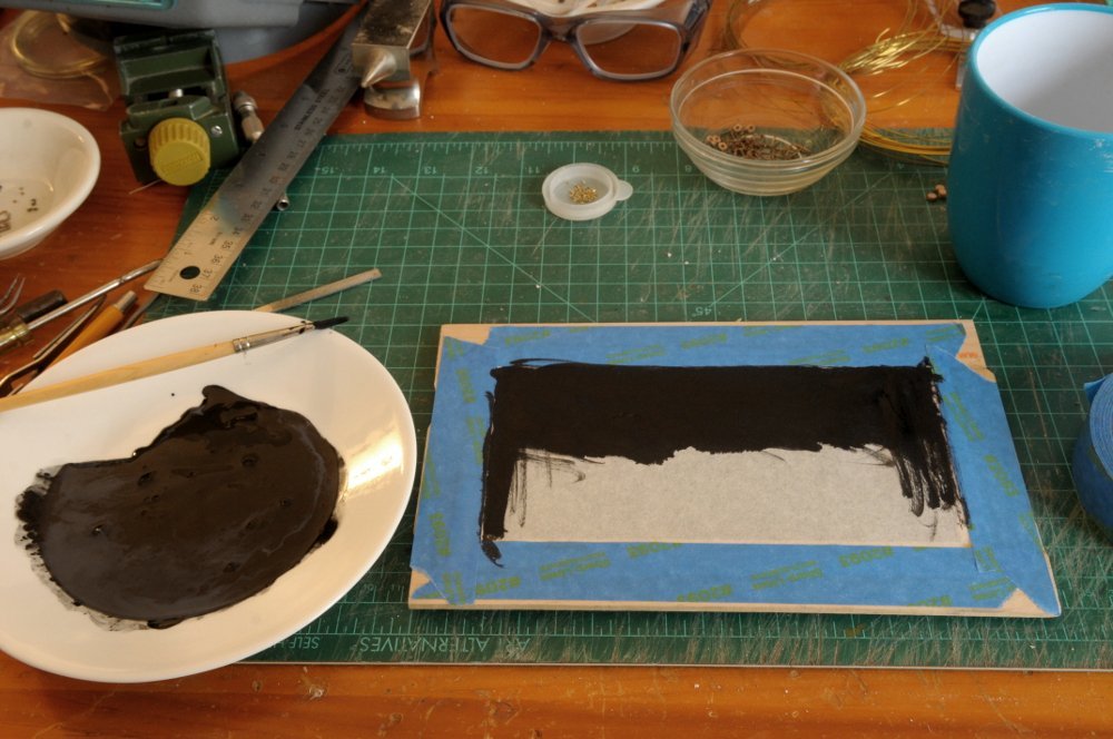
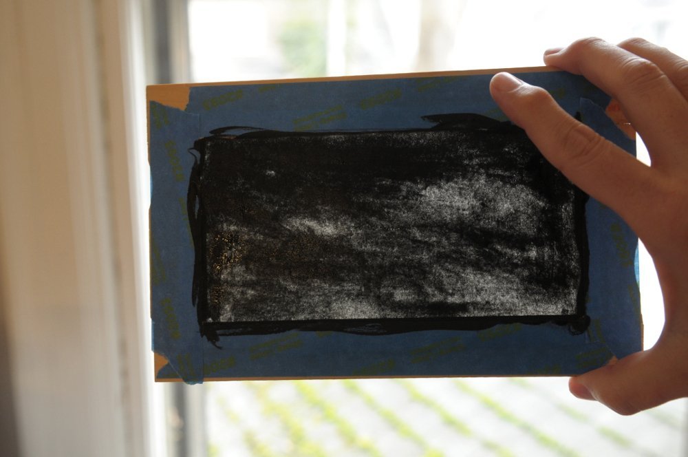
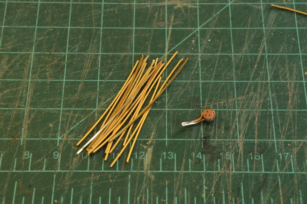
Dave, I think I want a light color for the hammock crane line, so actual rope seems to be my best option. But I appreciate the suggestion. And we do tend to be pack-rats. "Never know when I might need this!" Dowmer, yes, Silkspan seems to be an option here, and you will see my attempt at it. As I work on the hammock cranes, soldering the pins on and finishing them, I am also sidetracking into another project: making a bunch of metal thimbles for the rigging. When I get to blackening the hammock cranes, I want to be efficient, and the thimbles are something else that needs to be blackened, that I will need soon; so I will show my progress on making those now. Basically, I need to cut pieces of brass tubing, and flare them out. Easier said than done. They are tiny. To cut the pieces, I first tried using a my Zona saw with the 1mm OD wire held in a groove of scrap wood. Nope. Then I tried the rotary tool with a cut-off wheel. Nope. The biggest problems were holding the wire firmly enough to get a clean cut, and not losing the tiny cut-off piece. I settled on a method where I drilled a 1mm hole through a piece of scrap wood, and pushed the tube through-- The tube was then pushed back flush with the edge, and sawed through-- Then, a pin (which just happened to be the perfect diameter) was inserted into the end of the tube-- And the tube with the cut piece pushed through-- The pin held the cut off piece securely-- That piece after being sawn is too long, but it was made that way because I was afraid of snapping off the bit of wood on the edge, if I had made it thinner. So the next step was to drill another hole in some scrap wood of the right thickness (this part is described in David Antscherl's TFFM)-- And the piece then filed-- This worked sometimes, but what began to happen more often (as the hole got a little loose, or my filing not square), is that the piece ended up with skewed ends, as on this one-- The next step was setting the thimble on a hard surface, and punching it with a modified nail set punch-- This took some practice to get a good result. The end of the tube on the punch would flare, but not the bottom. Then I would turn it over, and the flared end would just flare more. After a few failures, I seemed to have better success if I barely started the flare, and then turned it over before punching again. I had a success rate of about 1 in 5. Partly because of the problem mentioned earlier about the skewed ends. If they were skewed, no dice, it would just skew more when punched. Here is a successful one, and another attached to a hook-- So decided to skip the filing step. Maybe it would have worked just fine if the pieces were closer to the right length to begin with. In the end I just pulled back a little (by eye) on the tube, rather than having it flush-- This gave me square ends, and the right length (more or less). I cut 20 or 30 of these this way, but haven't started punching them into thimbles yet. Hopefully I'll do better than 1 in 5. Now for some exploration into the Silkspan hammock covers. This is my first experience with this material. I made a frame out of old unused paint stirring sticks, and cut a piece of medium weight Silkspan-- This was then wet, and taped to the frame to dry-- Painter's tape is probably not the best choice, because it doesn't stick well when wet, but it seemed to work well enough. I then used some acrylic paint, diluted just a bit with water, and painted it on-- After drying partway it looked opaque enough, but when I held it up to the light, it seemed pretty transparent-- I'm going to give it another coat, and see how it looks. So, a number of things going on: fine tuning the hammock cranes (which consists of rounding the cut off ends and general straightening), making thimbles, and experimenting with the Silkspan for the hammock covering-- All for now, Ron
-
HMS EURYALUS by Matiz - FINISHED - scale 1:56
rlb replied to matiz's topic in - Build logs for subjects built 1801 - 1850
Beautiful work, Matiz! Ron -
Chuck, Since your captain clearly loves a good book, you will need a bookcase. Not too big, though. Ron
-
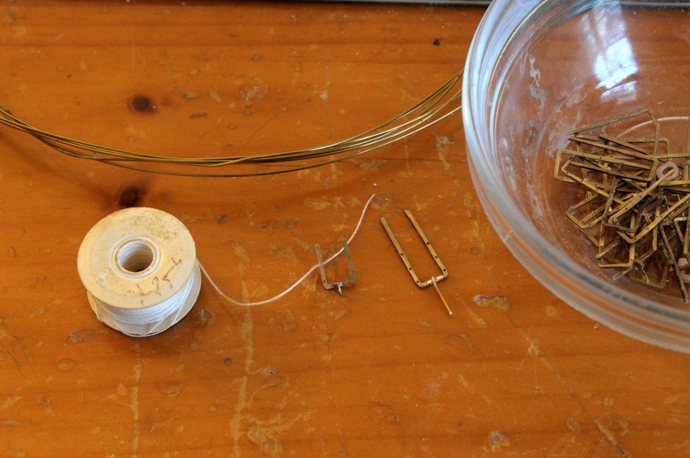
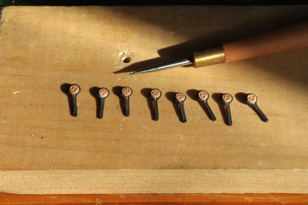
Another brief update: I tried making some rope small enough, but with the thread I had on hand, it wasn't quite thin enough. After thinking I might have to try enlarging the holes, I found (I think it came from Bluejacket) a spool of rope in my small stock that fit! I will dye it just a shade darker-- You can't quite make out that the line is through the hole, so-- I also tested soldering the pins. Since they won't be seen, I can overlap the brass, instead of butting it. This is a much easier joint to solder. I clearly missed centering the pin on this one (I maintain it moved while soldering!), but again, it won't show, and I'll drill each hole in the cap rail "custom" to match. (Or maybe I won't use this one!) I think I have now satisfied myself that these will work. While I continue the production of the hammock cranes, I am considering how to replicate the oiled cloth (which I guess it is) as shown on Glenn's model that covers the hammocks stowed within these cranes. All for now, Ron
-
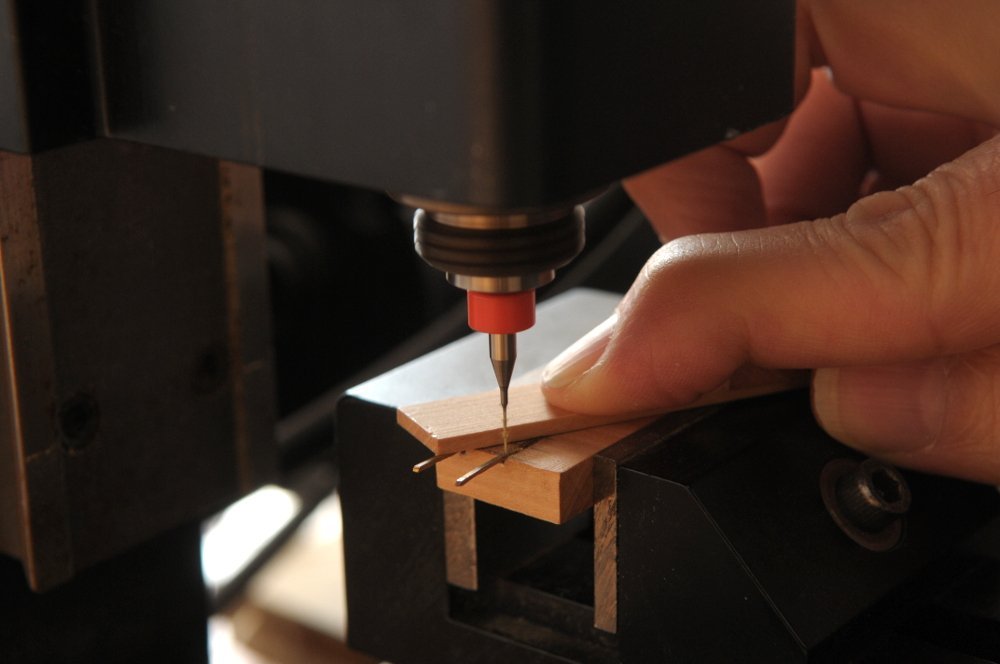
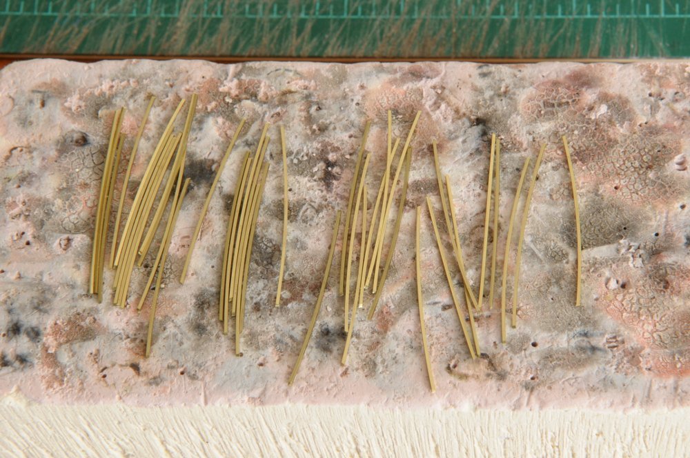
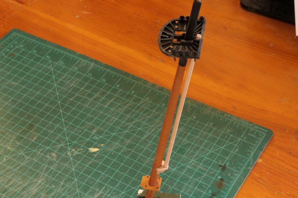
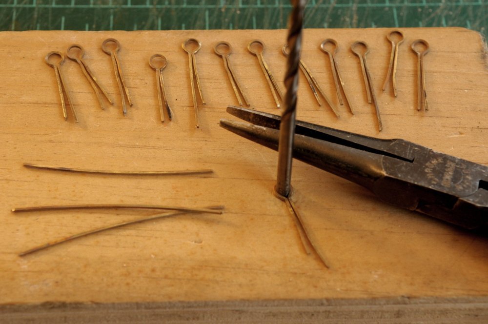
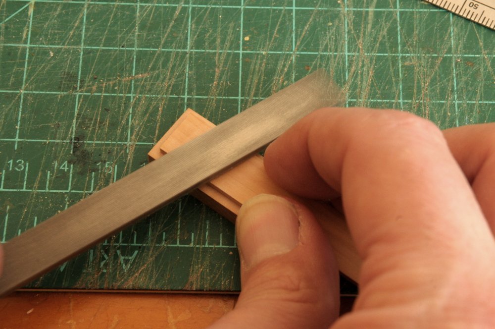
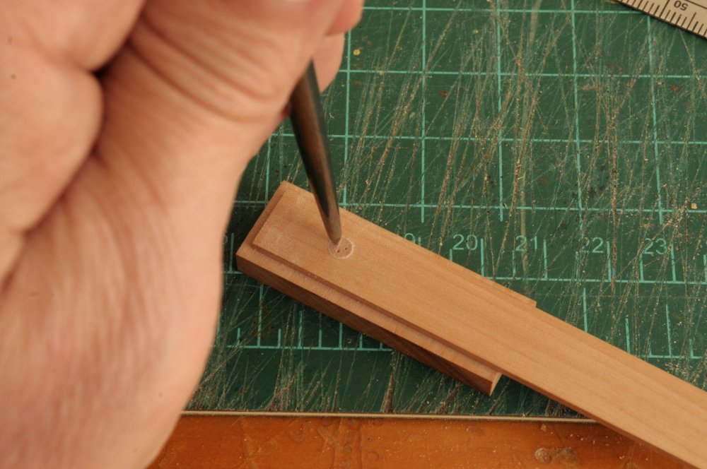
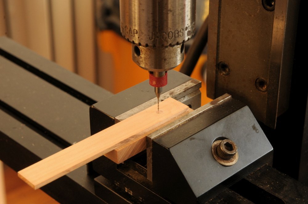
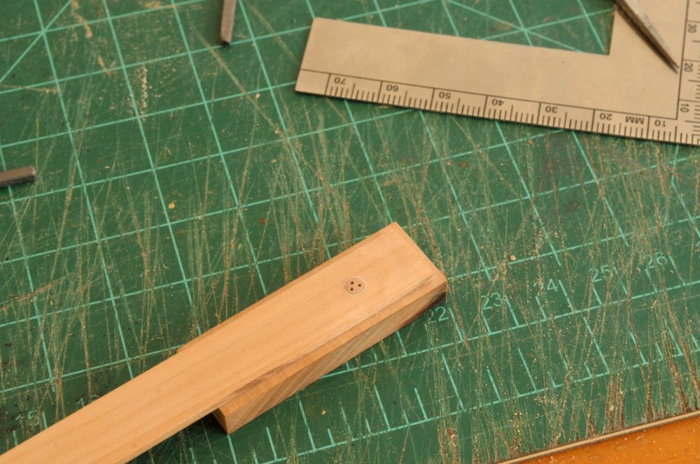
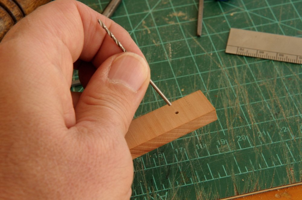
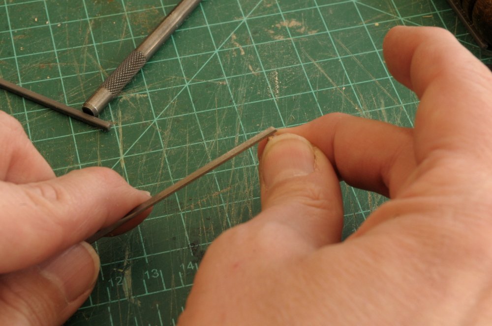
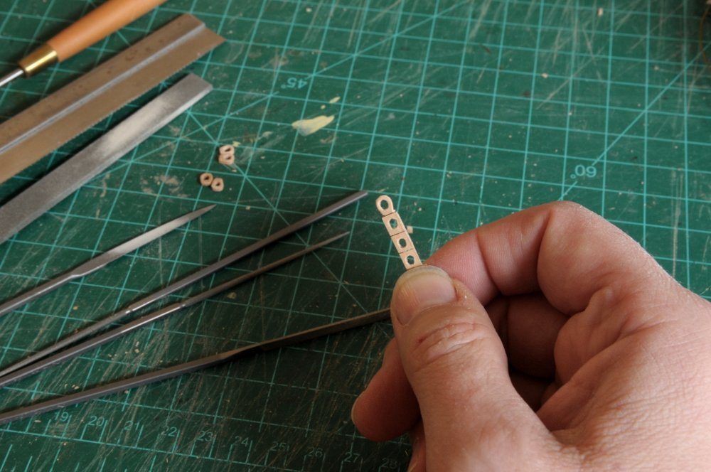
Thanks, Cisco and Theodosius, and all watching. Here is how I tackled drilling 228 holes with a #78 drill (.016" or .40mm)-- Two pieces ended up being deemed unusable, so I now have the 34 hammock cranes that I need, plus two extra-- I broke two more drill bits (for a total of three). Those carbide bits break if you breath hard on them. Actually, after the initial careless one, the breakage on the other two seemed to be related to how many holes I had drilled already (they may have been getting dull?), and how flat the piece remained held in the wood through the drilling--sometimes the piece lifted up when withdrawing the drill, in spite of my care to hold it in place. Now I need to trim them, file the ends, and hope that I can thread a line through the tiny holes. Hopefully I won't have to experiment on "punching" the holes a bit bigger. Oh, and soldering pins on the bottoms. All for now, Ron
-
Best of luck in your new location, Ben! Looking forward to seeing building updates! Ron
-
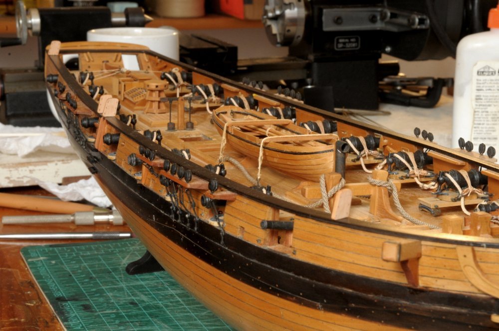
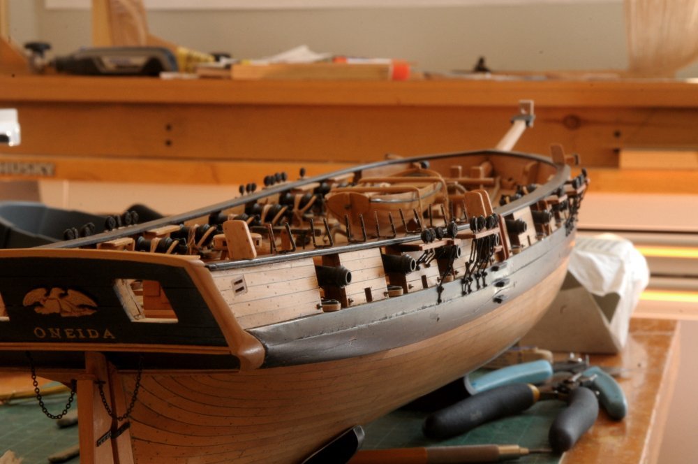
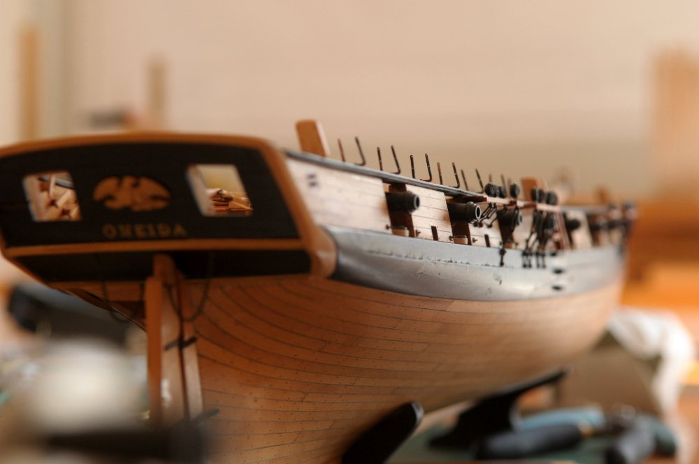
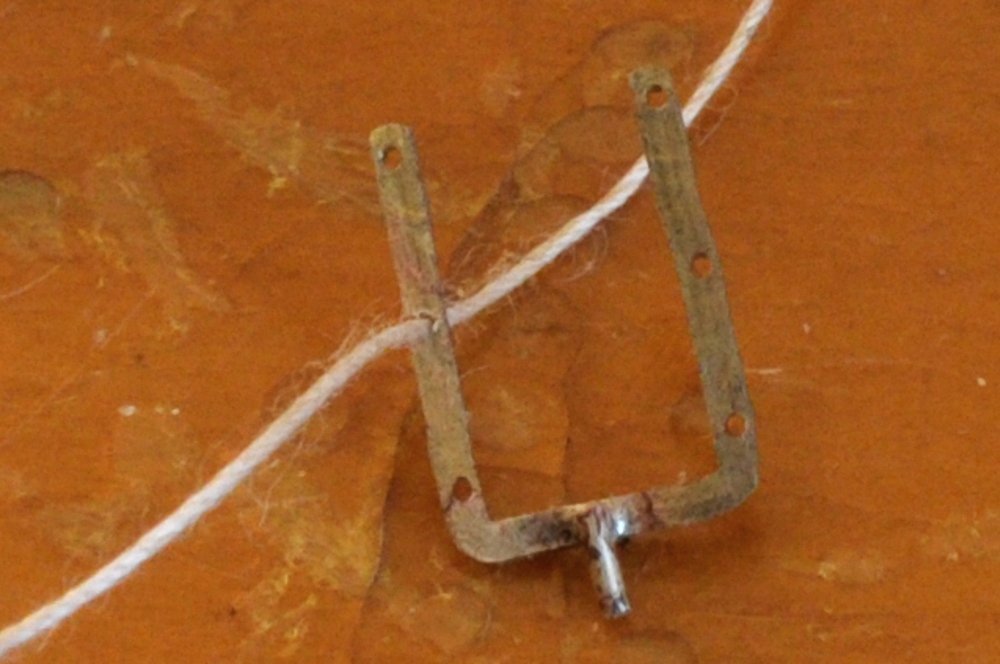
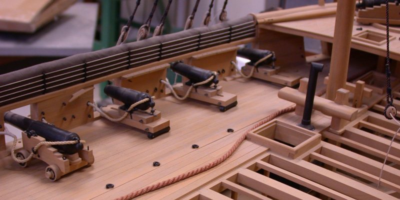
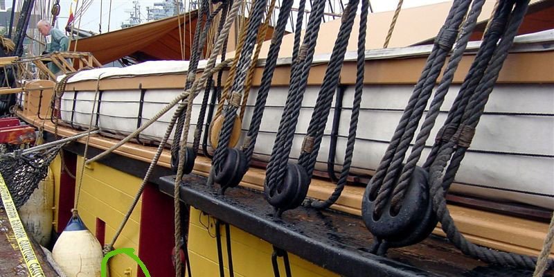
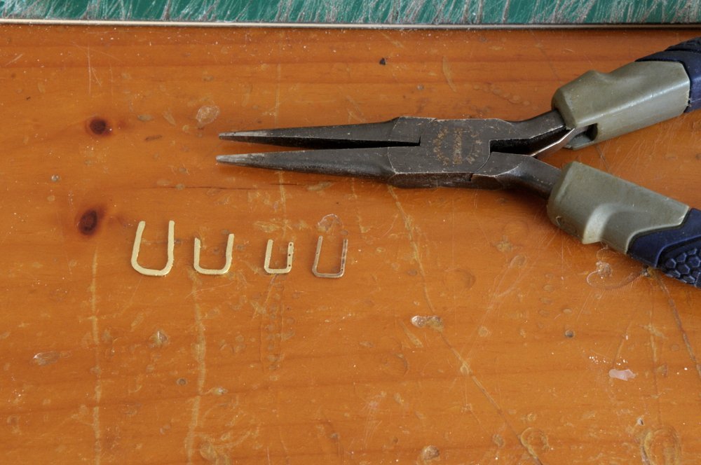
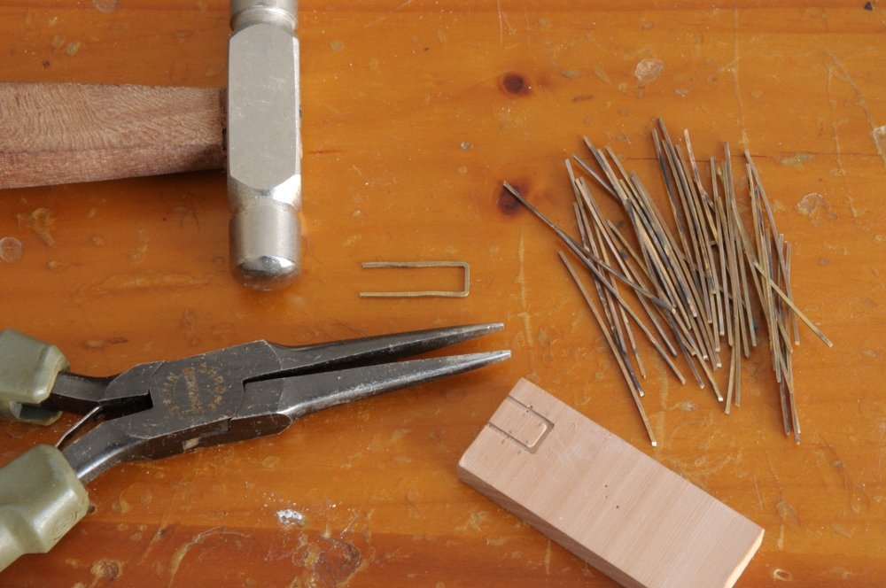
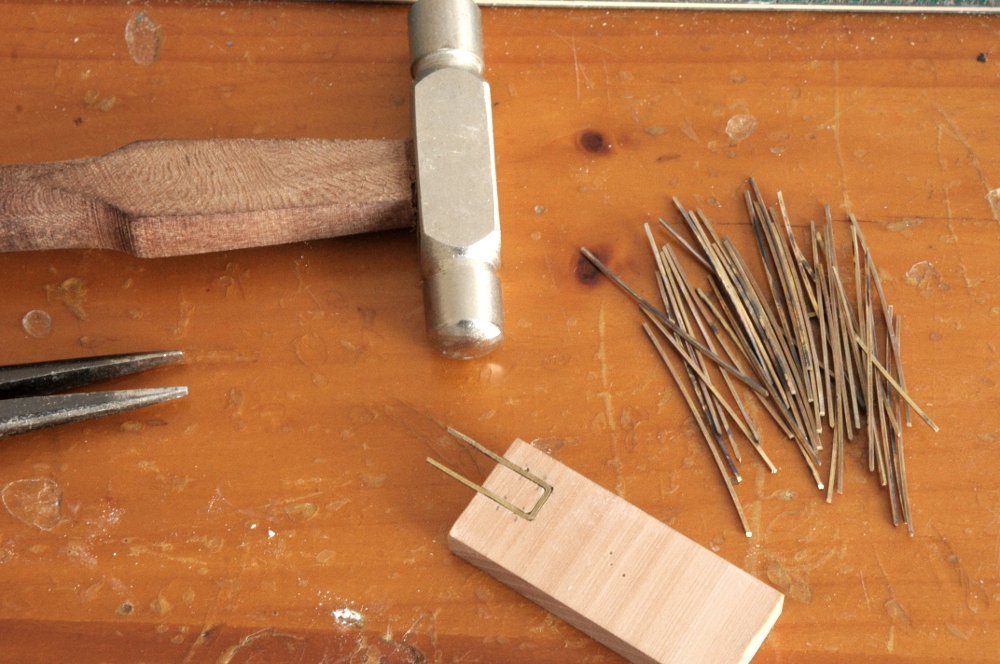
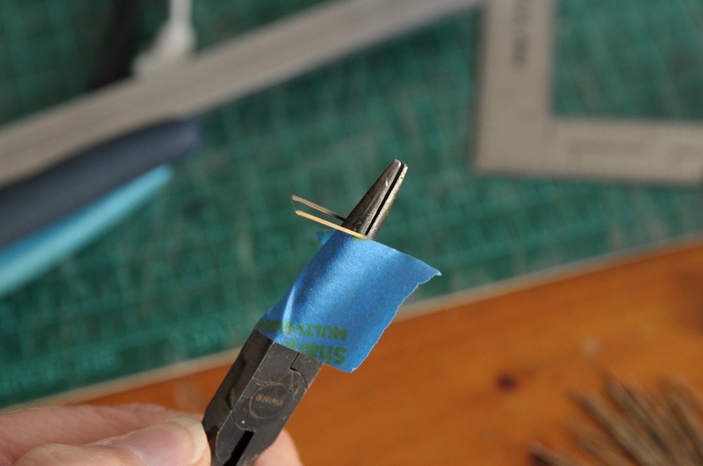
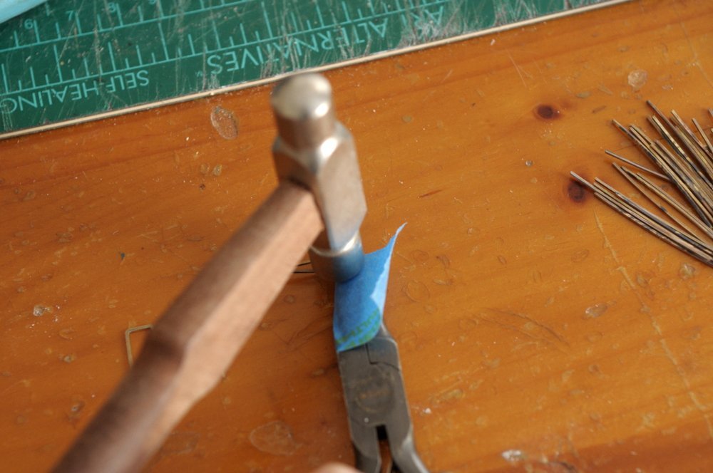
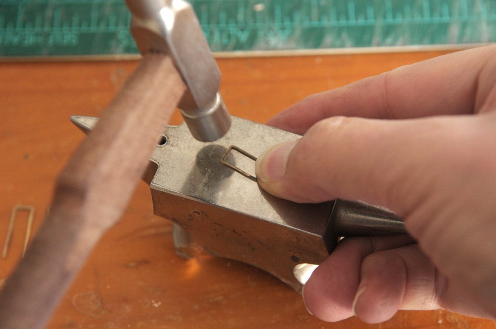
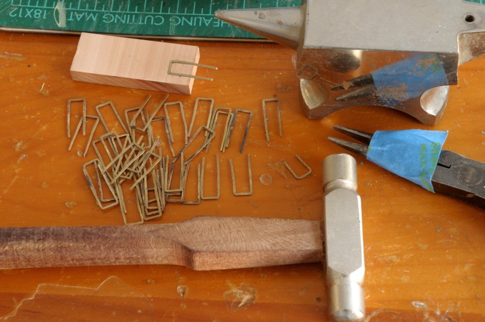
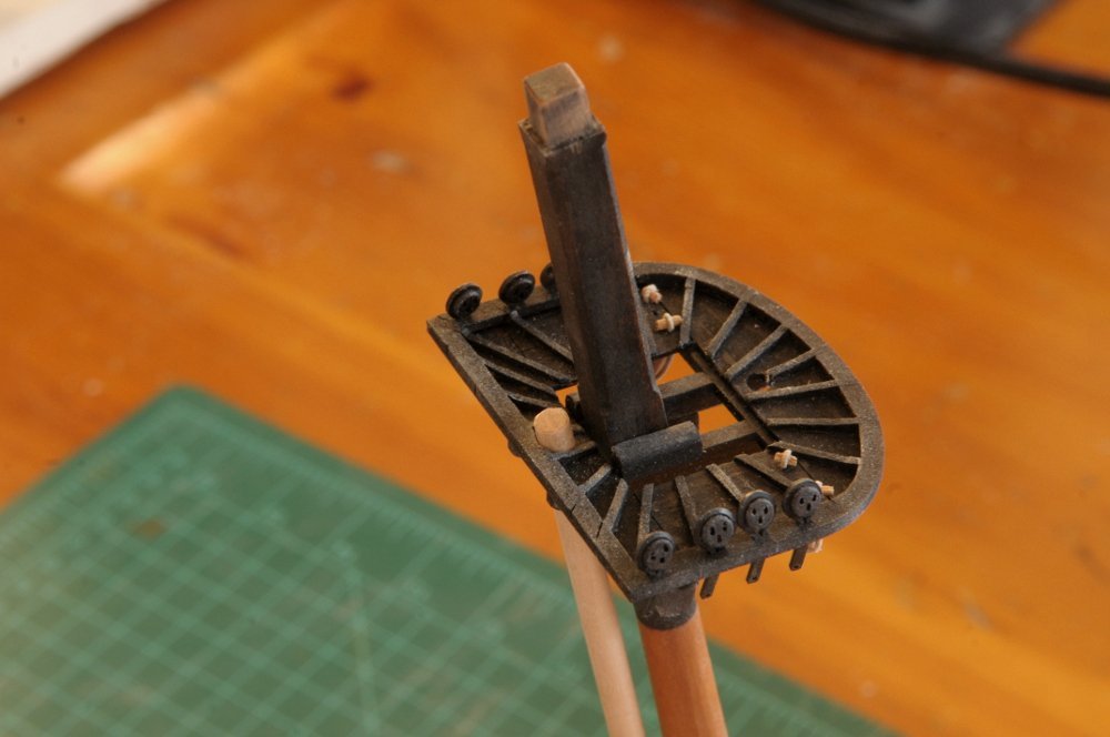
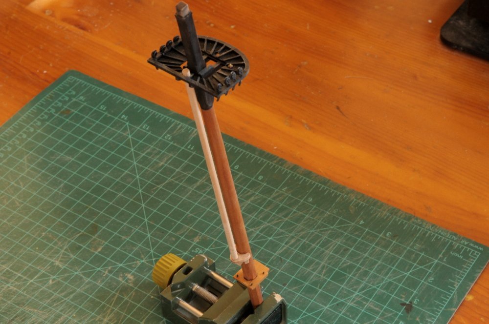
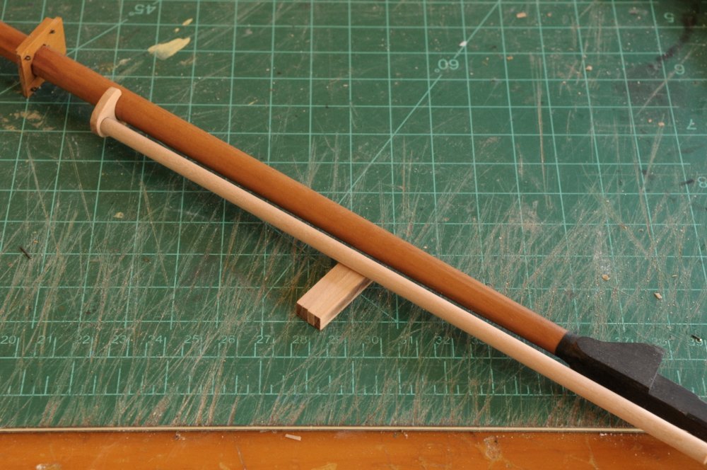
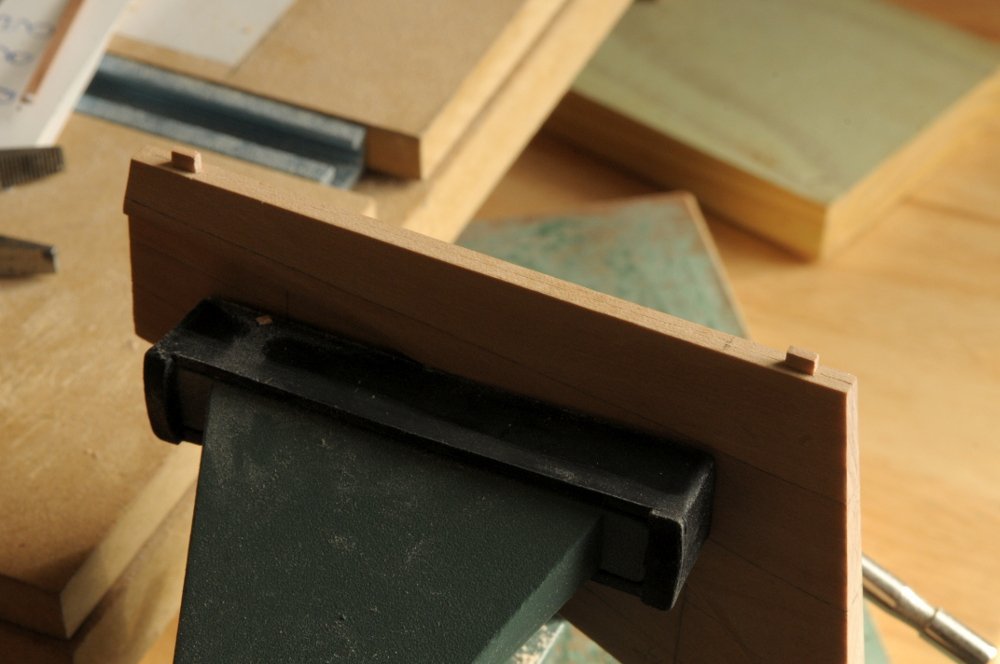
Skipping around some, I decided to tackle the hammock cranes. Although they will probably make getting to the belaying rails more difficult, on the other hand, I think they will be more difficult to install after the shrouds are on. I'm aiming for something like what is on the Niagara replica-- Only more like Glen Greico's model of the Brig Jefferson, without the wood rail at the top-- I'm going to make it a little easier on myself and do three ropes vs. four. Here are some attempts at figuring out the size, and exactly how to make them-- The first three are some 20 gauge square brass wire, bent, and pounded a little flatter. The first two are too big, and the third, which I tested drilling holes on, is actually a bit too small, though too thick. I was able, though, to figure out how to make a tight radius in the bends. The third is 22 gauge square wire, annealed, pounded just a bit flatter, and with some smaller test holes drilled. It's close to the right size, both overall dimensions and gauge of the wire, and I think this method will work, though it leaves no room for error on the hole spacing. I drilled one hole too far off center, and I also broke a drill bit. I'll have to be more careful, or I will be buying more bits to finish them. I figured out how many hammock cranes I will need (17 per side) and cut thirty-eight (four extra) pieces of brass-- These were annealed (heated to red hot) with a soldering torch. I also routed a groove in a piece of scrap wood as a guide to make sure they are bent to a consistent shape, and as well to hold the piece for drilling the holes (which hopefully will help with the bit breakage)-- The ends of the wire that extend beyond the block will be trimmed off-- I put a piece of tape at the spot that was the right width for bending the wire-- And the bends were given a light tap to make the radius tighter-- Then after some straightening and checking the squareness of the shape, the wire was pounded just a little flatter, mostly just to give me a few thousandths of an inch more width to try and center the drill on-- The holes will be drilled next. Hopefully that will be successful and I won't have to abandon this method. After the holes are drilled I'll solder a short pin to the bottom of each one to epoxy them onto the rail. At that point I may also adjust the angle of the legs to follow the bulwark angle-- All for now, Ron
-
Keep at it Cisco, that last batch looks good! Ron
-
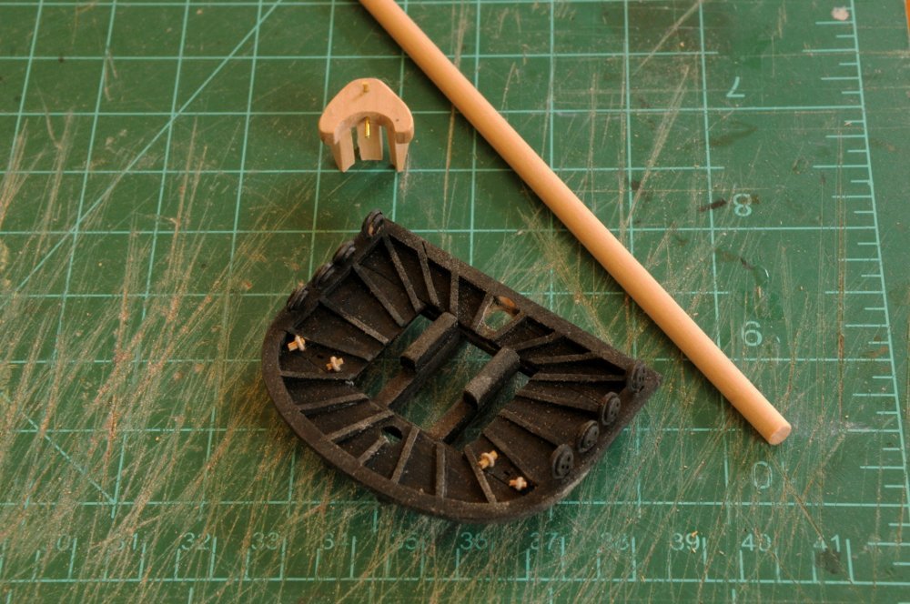
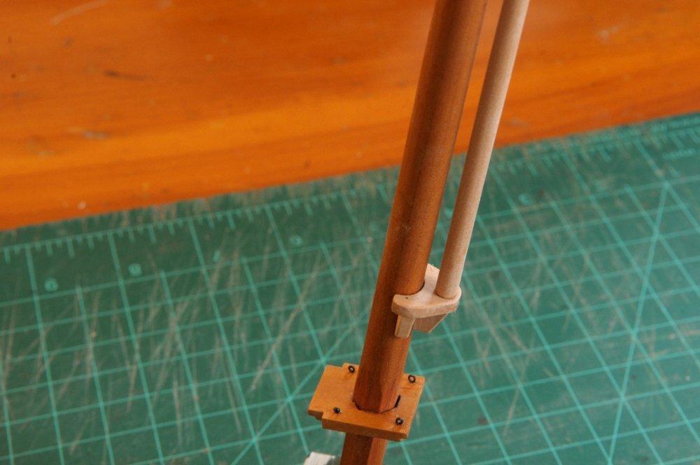
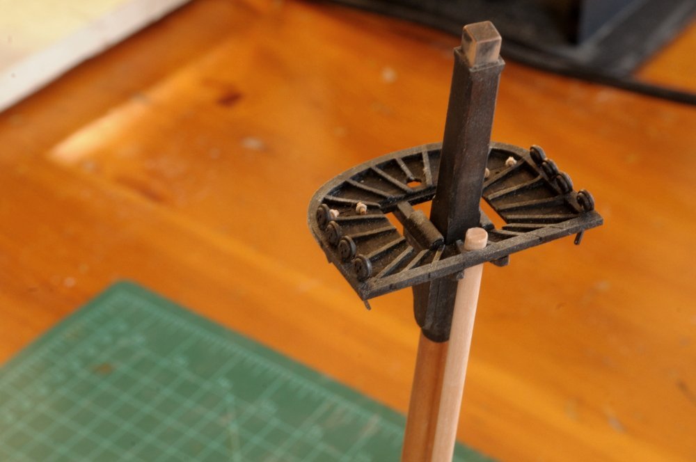
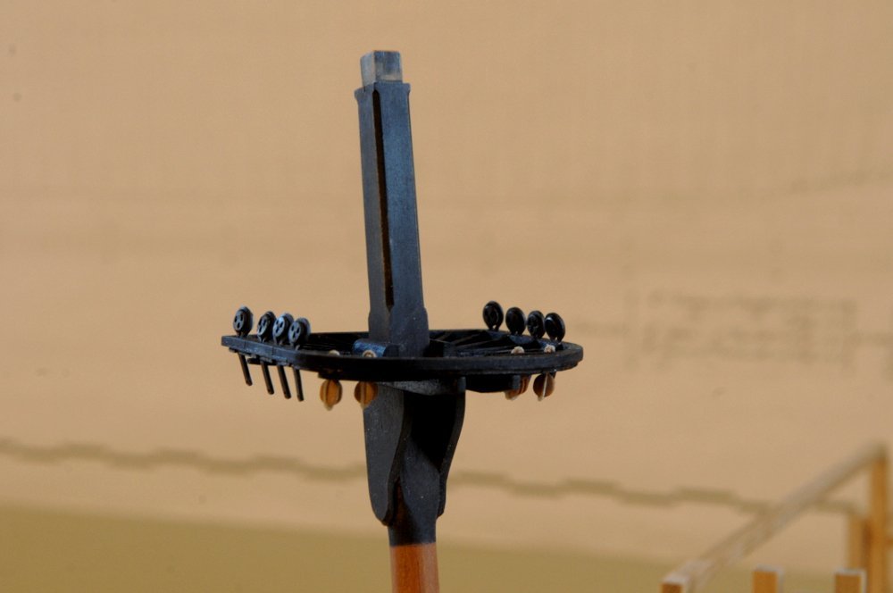
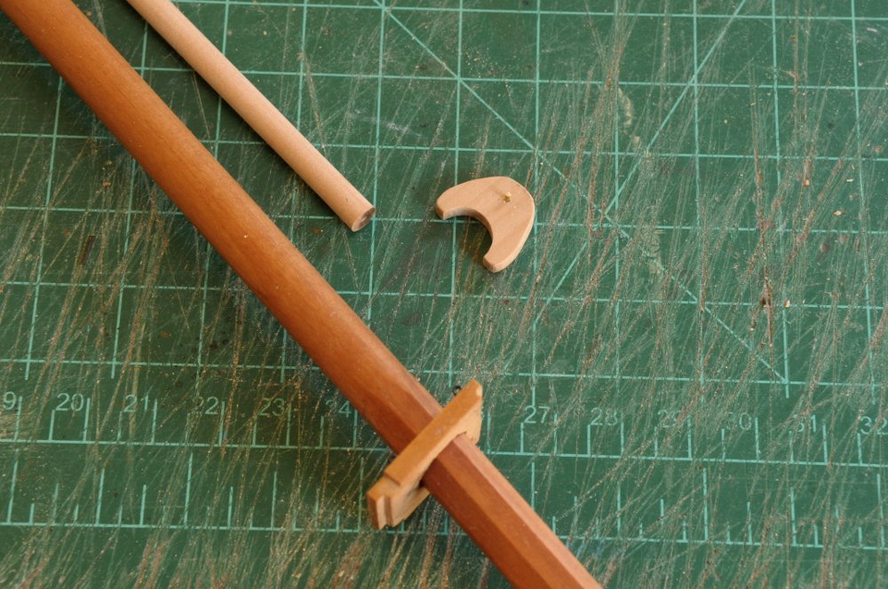
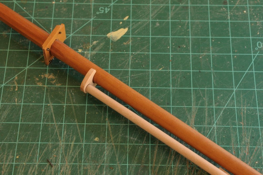
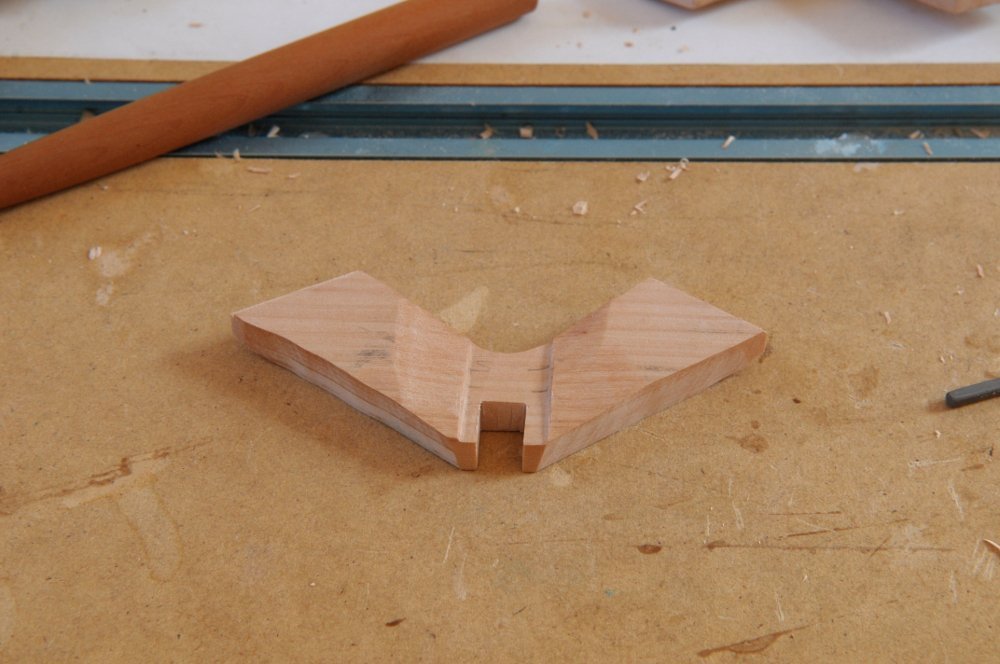
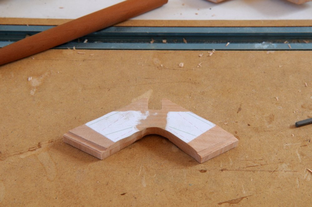
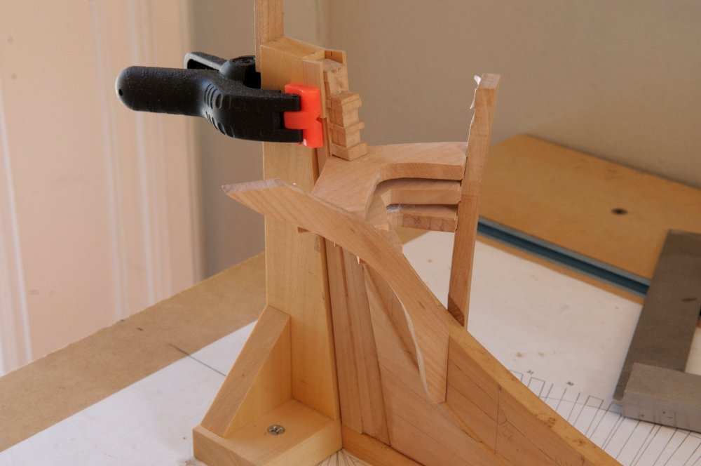
Thanks Håkan and bigcreekdad! I was sure my main top wouldn't have enough room on the aft side to have the trymast come up through it the way it is supposed to do. I was pleasantly surprised that there was enough room, just barely. I filed a hole in the middle of the aft end for the trymast. (I also spy a deadeye that didn't get completely blackened). The top looks pretty dusty!-- The seat for the trymast is just about done. I may do some further shaping. Here it is pinned temporarily to the main mast-- And fitting the top in place-- There is supposed to be a fid through the trymast into the trestle trees, and possibly a spacer block between the trymast and the mast just under the trestle trees. I'm not sure I'm going to elect to show those. All for now, Ron
-
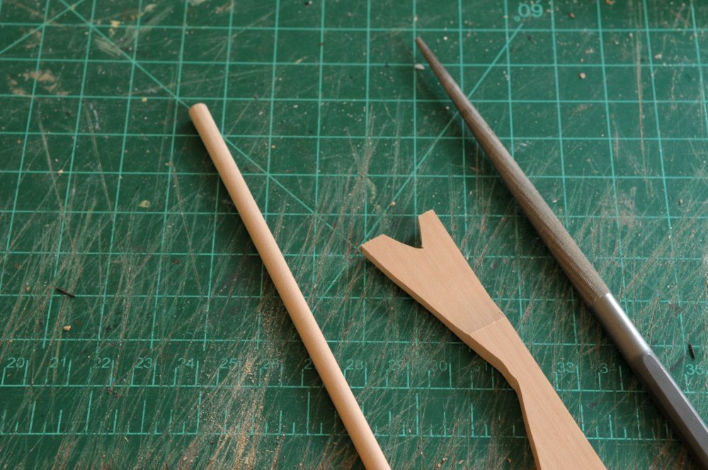
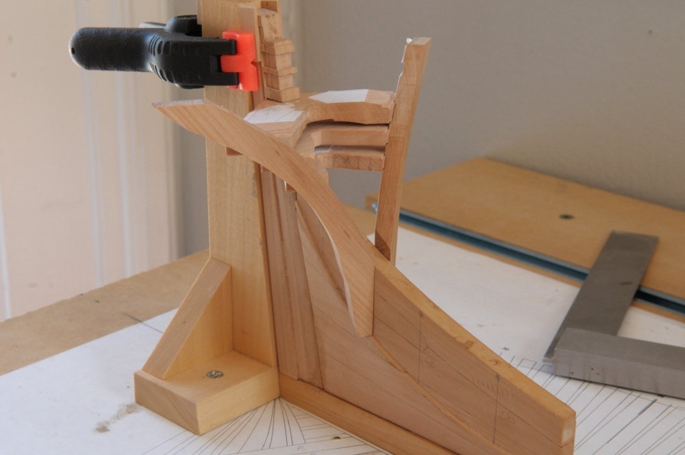
Continuing on-- After all the futtock plates were made and blackened, the deadeyes were crimped back in, and being held firmly, this was a good time to refine them with the easing of the lanyard holes-- Next the futtock plates and deadeyes were installed on the tops. I contemplated the light colored deadeyes, wondering if I had made a mistake to make the ones on the channels black. But the die (dye) had been cast, and the top deadeyes were blackened (in situ) to match-- You can also see some blocks hanging below the tops. You can't tell, but the outside one is single, and the inner double. I initially had three blocks on each side and they looked too crowded together, so I eliminated the middle one on each side. I'm not sure I can really do that though. I'm sorting through the rigging requirements (which are overwhelming), and I think I will have to put the middle block back. The outer blocks are needed for the spritsail, and the others for the bunt and leech lines of the yards on the mast, so four sheaves on each side needed, at least for the fore top, I believe. I'm going to do single, single, double, on each side. Theoretically maybe it could be double, double, but it doesn't seem right to combine the spritsail block with one for the main yard. While I study rigging, and some other bits and pieces that need to be added to the tops, I'm making the trymast. The trymast is a secondary mast on the aft side of the mainmast where hoops for the boom sail (placeholder while I look up the correct name) will travel. I've got the trymast, and the start of it's support from a piece of scrap-- This is further shaped, and test fit to the mast-- The support bracket needs some support brackets of it's own. And I have to figure out how the trymast and the top resolve themselves. All for now, Ron
-
Thanks Ed. Yes, my shop has grown enormously from the first days. I cut the original masts from a billet with a jewelers saw, and spent hours (days) sanding them flat and square. Now it's a few minutes work. But I spend most of my time still with files, chisels, and sand paper. I'm getting the fore and main tops ready. One of the tasks is making the futtock plates for those deadeyes I showed in the last post. I used the method described by David Antscherl in Vol. 4 of The Fully Framed Model. Here is the test piece, and a bunch of square wire cut for the rest-- The wire I bought was supposed to be "dead soft" meaning it should be not spring back when bent, but I found I still had to heat it red hot to make it truly malleable. The wire pieces were bent around a drill-- They were then silver soldered at the "bottom" end. This would allow them to be bent back apart to insert the deadeyes. This shows a series of them ready to solder. You can just see the dab of solder paste about halfway along each piece-- . That arrangement didn't work so well. Only three of the pieces soldered well, because when liquid, the silver followed gravity rather than the gap in the wire. Turning the pieces this way worked better-- Here are some ready to be soldered, some successfully soldered and filed smooth, and some cut to length with a hole drilled for a hook-- All for now, Ron
-
HMS Euryalus 1803 by rlb - 1:48 scale
rlb replied to rlb's topic in - Build logs for subjects built 1801 - 1850
Thanks, JJ, druxey, Michel, and all those looking in, and liking. I appreciate the encouragement. I took a leap of faith and followed Ed Tosti's lead from his Naiad books to start permanently gluing (well, there's always Isopropanol) each transom as it is fit. I really hate gluing anything until I feel confident about the whole assembly, but here goes-- The lowest transom is glued to the fashion timbers only, not to the sternpost, nor the fashion timbers to the deadwood-- I wasn't sure how the assembly would work as it's added to, but it's really quite simple. Here's the next transom in place on the sternpost, and the previous transom and fashion pieces sitting on the deadwood below it-- The fashion pieces/transom are then just slid up the deadwood, the lower transom fitted into its spot on the sternpost, and the upper transom test fitted with it's tenons into the fashion pieces-- If all is satisfactory (and believe me it took many tests and refinements to the second transom piece before it was satisfactory), then it is now glued to the fashion pieces-- Now on to the third (from the bottom) transom. This is the deck transom, and it must slope down and to the sides. I'm on the third try with the piece pictured here-- I took a different approach shaping this one. Instead of shaping it all over at the beginning, I just thinned it at the top (stern) and two lower forward ends, and made sure those fit, as they do in the photo above. Here is the piece showing the bottom-- And the top-- Once this fit was good, I then tapered and smoothed the top and bottom before gluing it into place-- So far so good. Remember the transoms are glued to the fashion pieces here, but not to the sternpost, and the transom/fashion piece assembly can be taken off . There is an enormous amount of fairing that will need to take place on the transoms and fashion pieces once it's all together. And I don't know how much of that I will do with it as a separate assembly, or glued finally to the deadwood and sternpost. We'll see. I am pleased so far with the general method. All for now, Ron
- 122 replies
-
- 16
-
-
- Euryalus
- Plank-on-frame
- (and 4 more)
-
ancre Le Gros Ventre by ChrisLBren - 1/36
rlb replied to ChrisLBren's topic in - Build logs for subjects built 1751 - 1800
Looking good, Chris. Glad you're back at it. Ron -
HMS Euryalus 1803 by rlb - 1:48 scale
rlb replied to rlb's topic in - Build logs for subjects built 1801 - 1850
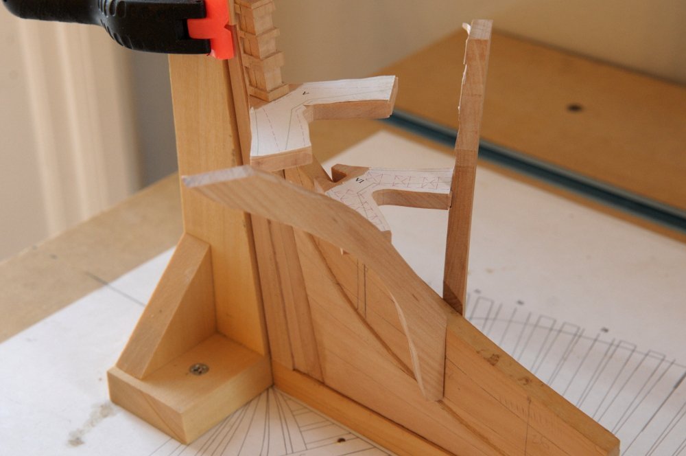
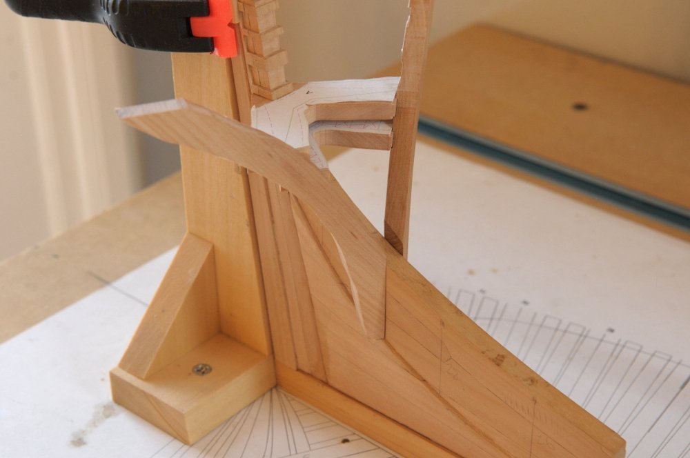
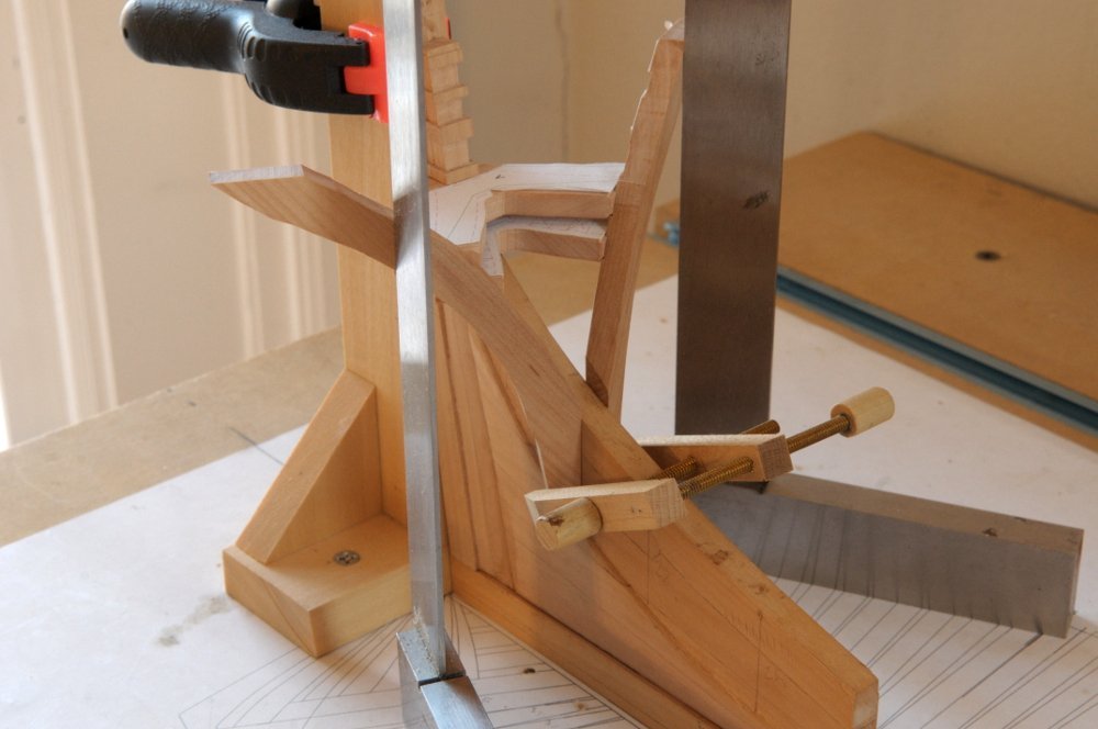
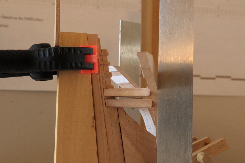
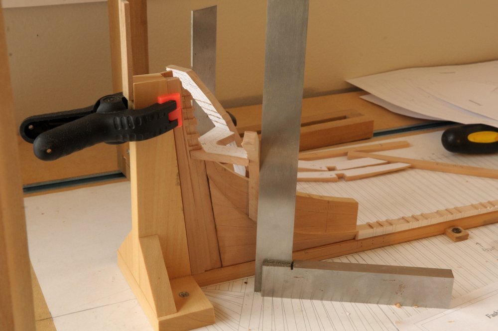
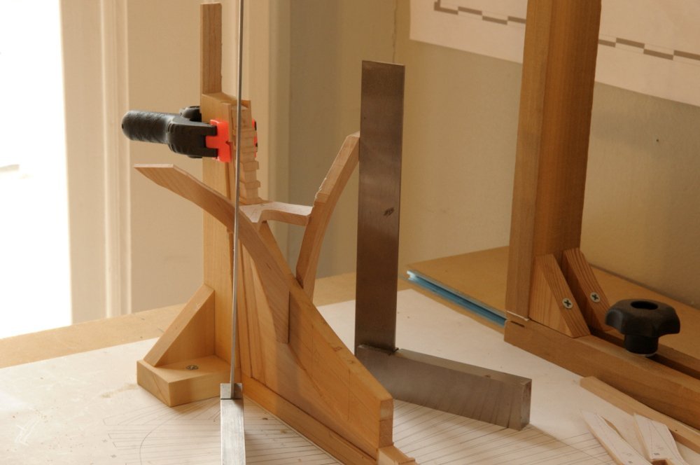
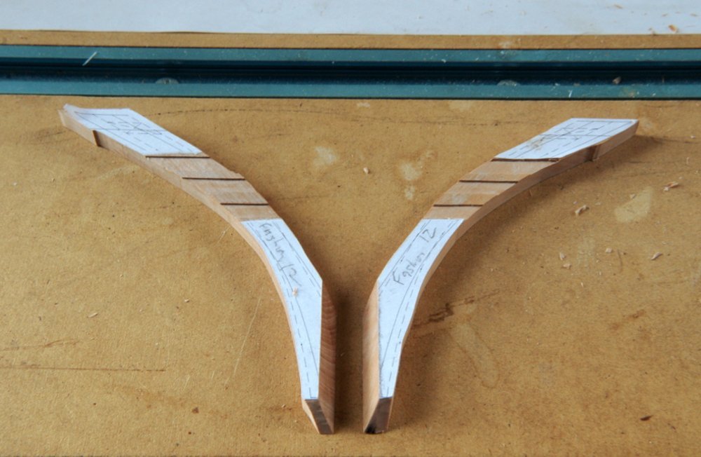
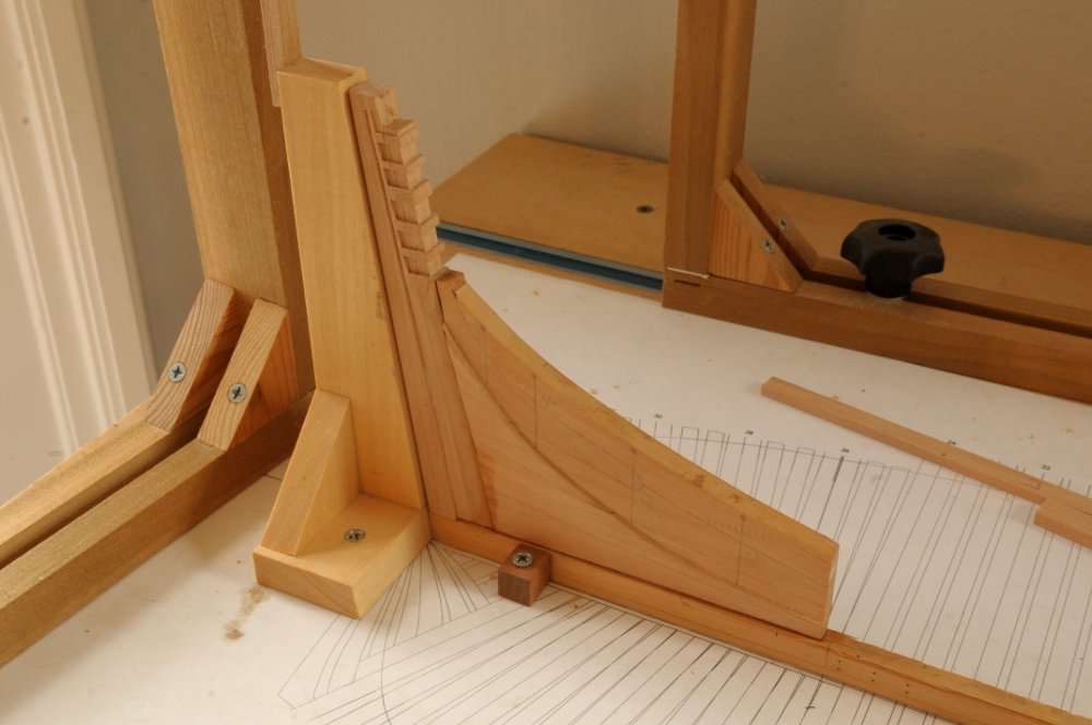
Thanks so much Allan. Incremental progress. I'm now trying to put together the transoms and fashion pieces. So far I've had to cut new transom pieces. I had shortened them too much when fitting them to the sternpost earlier. I cut a mortice in the fashion timbers, and tenons on the first transom, and here I have the lowest transom dry fit with the two aft fashion timbers resting in place-- The correct angle of the fashion timbers is verified with the squares-- I milled and chiseled out the next couple mortices in the timbers-- And am starting to fit the second transom-- This is all very slow going. I've had to recut the third transom also. It has a complex shape that needs to match the round up of the deck that it supports. Though none of these pieces (transoms and fashion timbers) have been faired at all, that third transom needs a lot of shaping to get it to transition from the slot on the sternpost down to the mortices on the fashion timbers, which should be about five scale inches down. All this seems to be going okay so far (apart from having to re-cut all the previously done transoms); hopefully I won't discover some egregious error that makes me start over, as with the bow timbers. Ron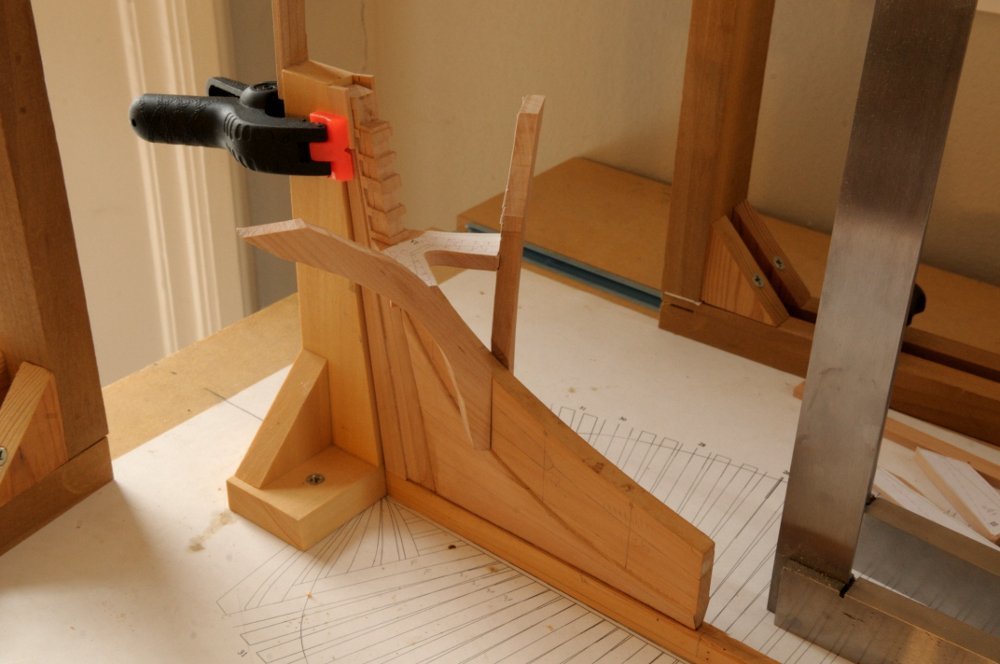
- 122 replies
-
- 16
-
-
- Euryalus
- Plank-on-frame
- (and 4 more)
-
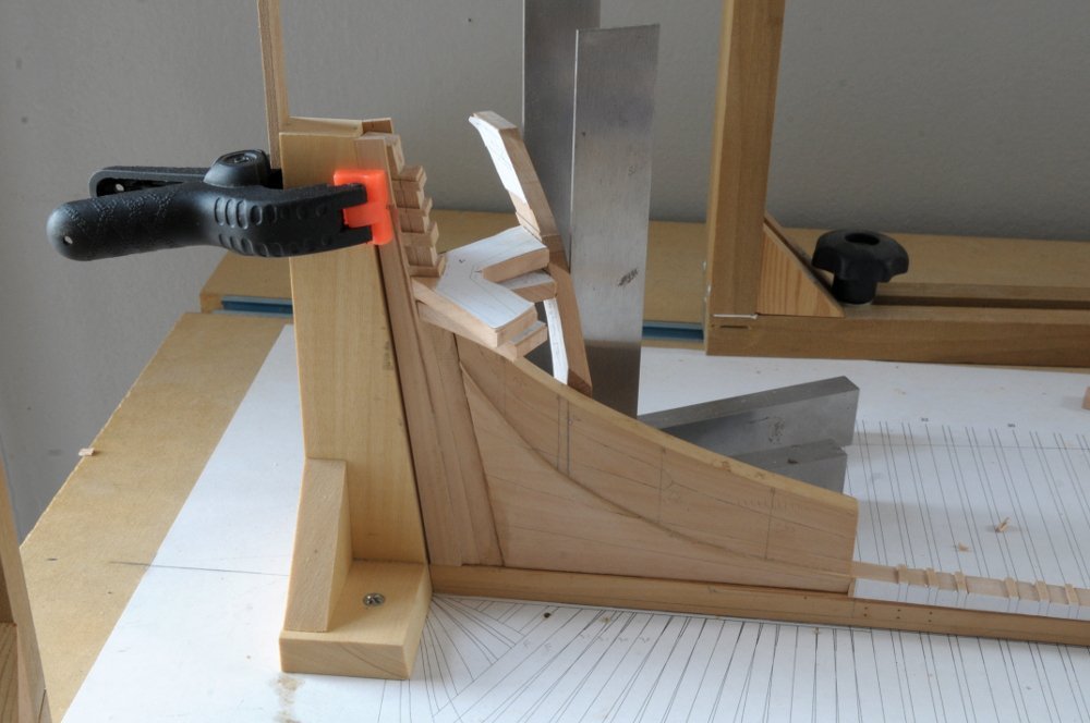
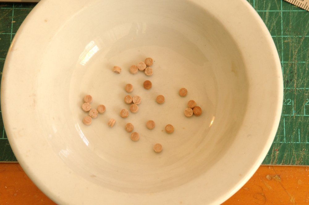
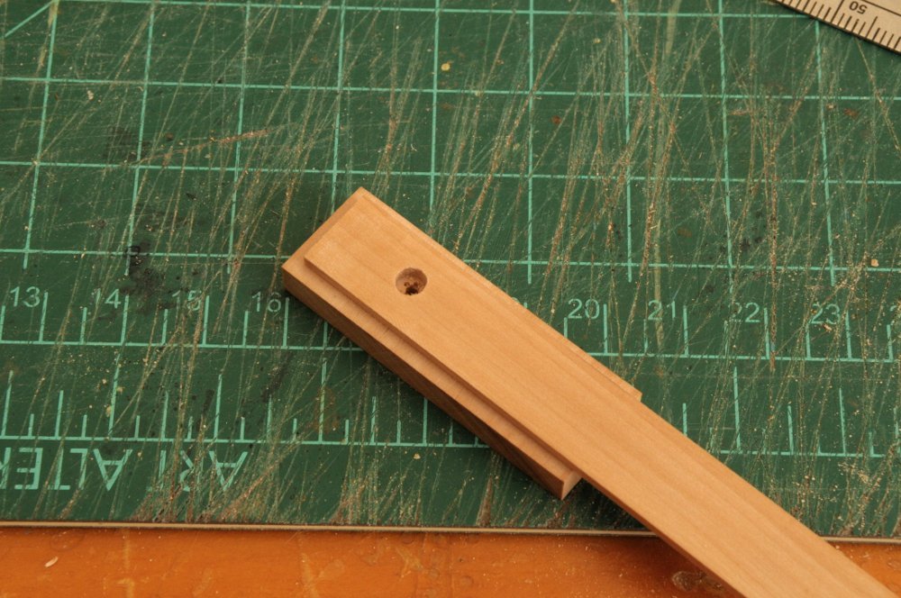
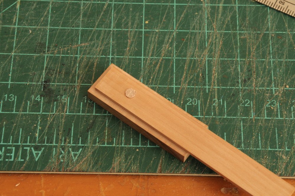
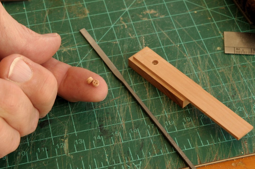
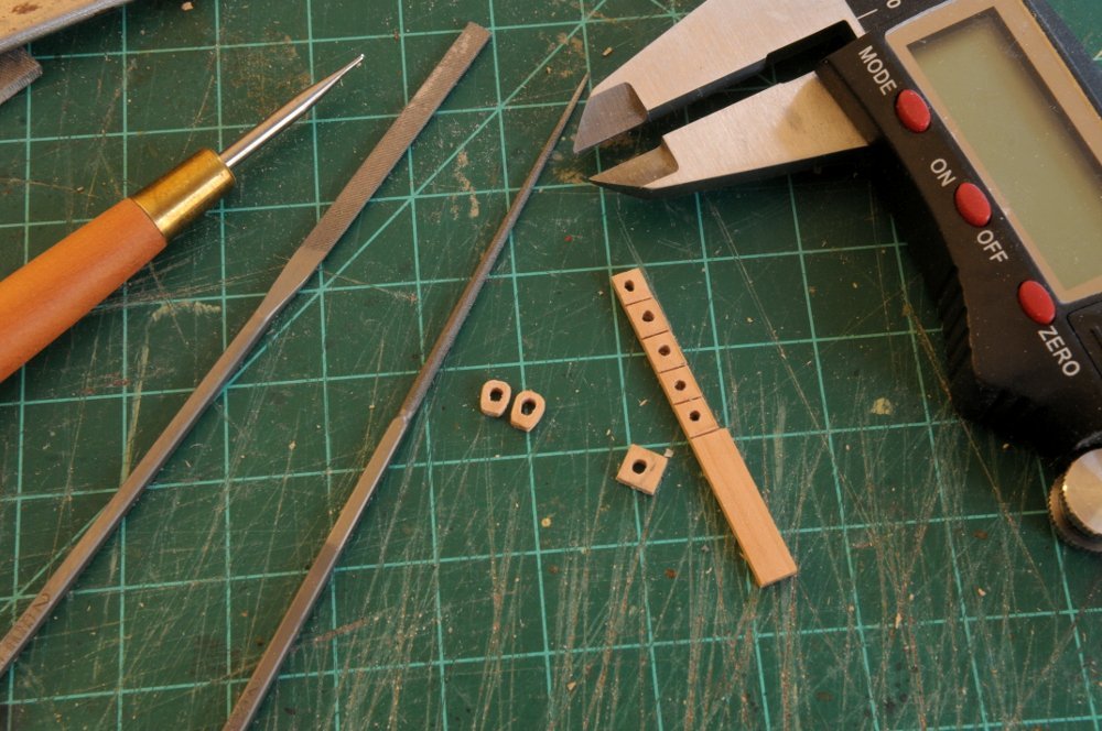
I thought I would share my method for making deadeyes. I made a bunch a long time ago for the main and fore shrouds, and half what I needed for the topmast and topgallant backstays. They were about 5mm and 4mm respectively. I made them using a method described in Underhill's book, and it worked out fine. The little jig is very fiddly to make. The method is shown from post #184-198 in this log. However I now need 32 topmast shroud deadeyes at 3.5mm, and 12 more of the backstay deadeyes at 4mm. Partly because of the smaller size, and partly because I have better tools now, I wanted to try something that might be more precise. This first batch is the 3.5mm set. I turned a squared piece of pear down to 3.5mm, and then scored it on the lathe with grooves for the futtock plates, and cut-very slight cut off grooves to help with parting them off with a saw. While the dowel was still on the lathe, one by one, I smoothed and rounded the outer edge, then cut it off. I didn't take pictures but here is the result-- You can see they have one smooth side, one rough side, and a groove. (Noticeable on one of the deadeyes standing on edge.) Next I drilled a hole in a piece of scrap wood just under 2mm thick (the thickness the finished deadeye needs to be), filed the hole to to 3.5mm diameter, and glued it to another piece of scrap wood. This has a smaller hole drilled through it centered on the larger hole-- A deadeye fits very snuggly in the hole, the rough side slightly proud-- The rough edge is filed off flush with the surface of the wood-- I filed the one shown below just a bit more with a smaller file after taking the photo-- I then marked by eye the spots for the holes to be drilled-- And drilled them on a mill. I wasn't great at locating the drill precisely at the marks, so I tried drilling a couple by hand. I could get the drill in the mark very easily that way, but at that small size, my accuracy (keeping the pin vise vertical) wasn't good enough. After some practice with the mill, I could locate the drill above the punched markings more quickly and pretty accurately-- The deadeye is then pushed out from behind-- And the flattened surface is rounded off with a file-- Here are two finished-- It took me about 5 before they started looking good. The first few had problems with my marking of the holes with the right spacing, as well as the stated problem with hand drilling them. I started with one spare, so I'll ponder whether the first are okay to use, or if I have to turn a few more blanks. All for now, Ron

-
Thanks JJ, Going off course a little bit, I worked on making some closed hearts for the bowsprit stays and shrouds-- I need two different sizes--4 for the stays, and 4 slightly smaller for the shrouds. After doing a few after cutting them off, I realized it would be much easier to shape them before cutting them off-- Now I need to make a bunch of deadeyes for the topmast shrouds, as well as the backstays. All for now, Ron
-
HMS Euryalus 1803 by rlb - 1:48 scale
rlb replied to rlb's topic in - Build logs for subjects built 1801 - 1850
I made 4 card templates, and sanded the area of the deadwood below the bearding line. In between sessions of doing that, I beveled the aft side of the sternpost- After this was done, I glued the sternpost to the keel, and went back to sanding the deadwood. When I was satisfied that I had done enough there, I cut two shallow mortices into the bottom of the deadwood assembly, and then glued in two small tenons. These weren't meant to be historically accurate, but would add some strength, and help in keeping the piece aligned when gluing the deadwood to the keel and sternpost-- The tenons were filed down until they extended only about 1/32nd of an inch. I then cut two shallow mortices in the keel and glued the deadwood to the keel and sternpost. I had also morticed and tenoned the sternpost to the keel when I glued it to the keel earlier. I did not tenon into the sternpost from the deadwood. Here is the sternpost and deadwood glued to the keel. You can see 4 pencil lines on the upper part of the deadwood (the fourth is barely visible) that had marked the locations for using the card templates-- Next will be work on the transoms, and fashion timbers. All for now, Ron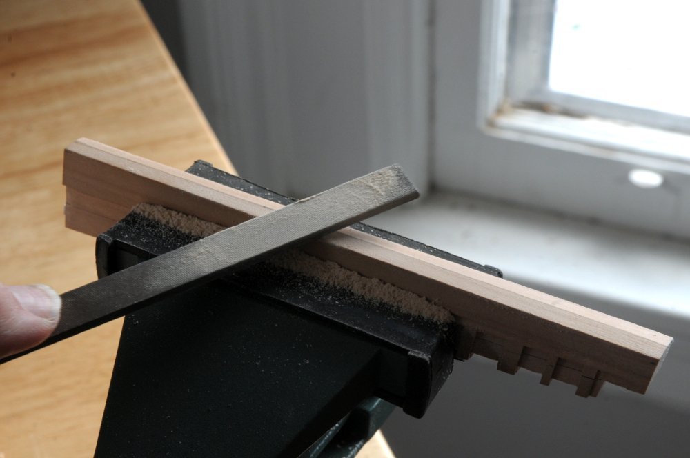
- 122 replies
-
- 18
-
-
- Euryalus
- Plank-on-frame
- (and 4 more)
-
Tom, I don't know what the directions call for, but it seems odd to me that the caps are laser cut into the carriage sides. I think it would be better if you sand that off, so it looks like the red carriage to the right, and then use the pe caps bent over the cannon trunnions, although it would be more fiddly as Nipper says! Ron
- 144 replies
-
- 1
-
-
- HMS Speedy
- Vanguard Models
- (and 1 more)
-
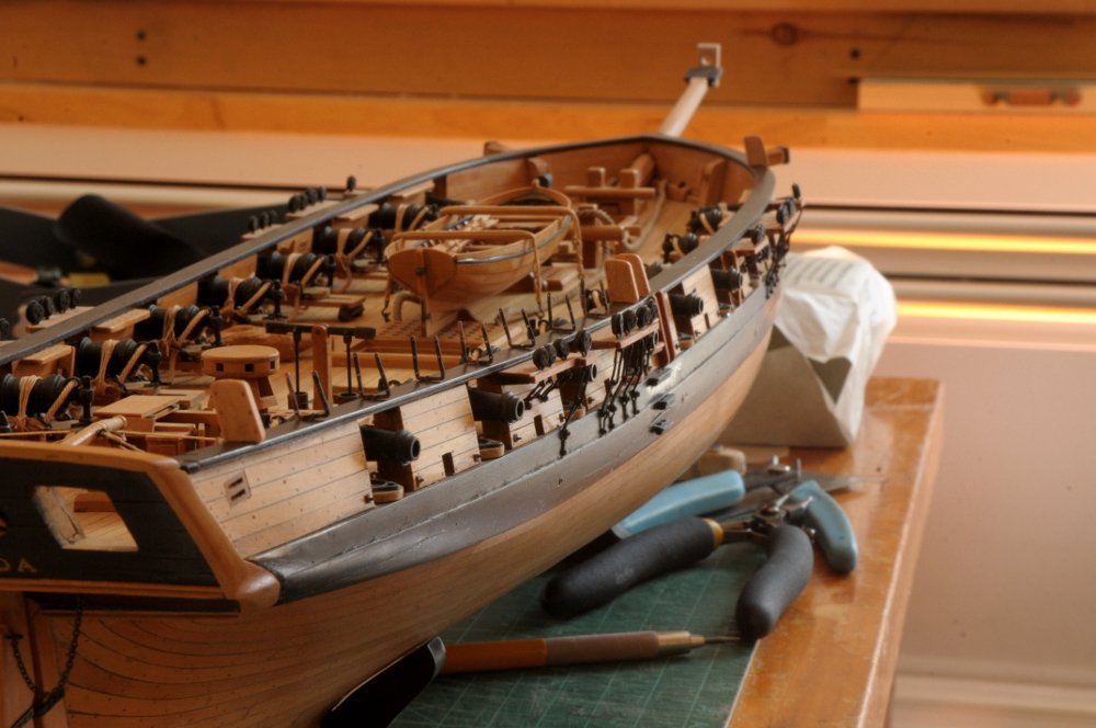
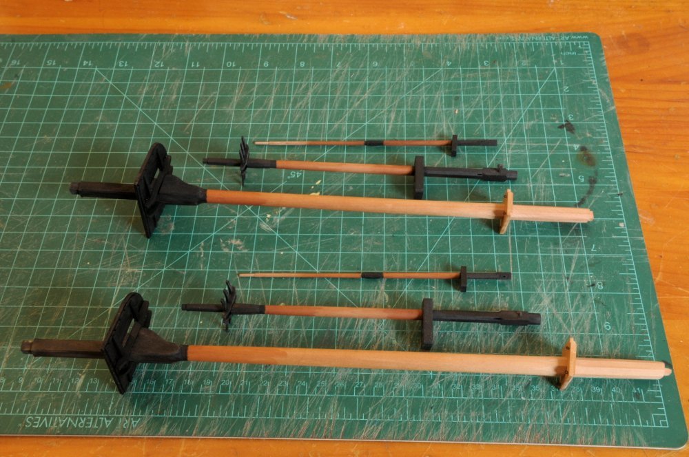
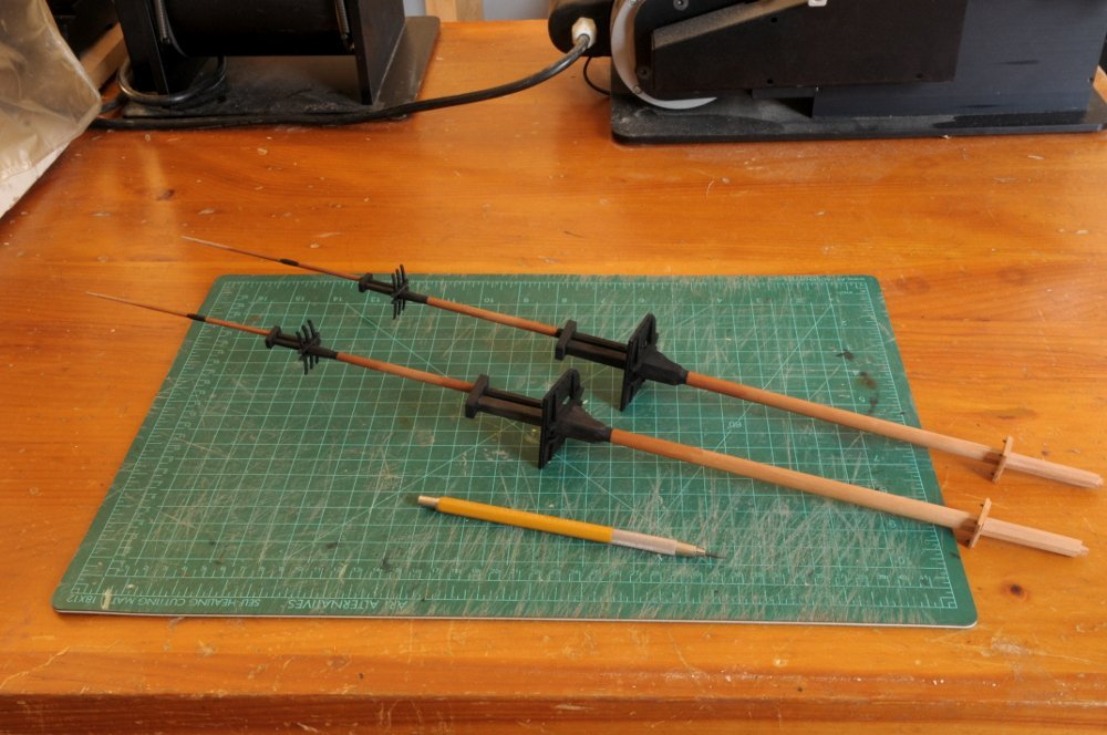
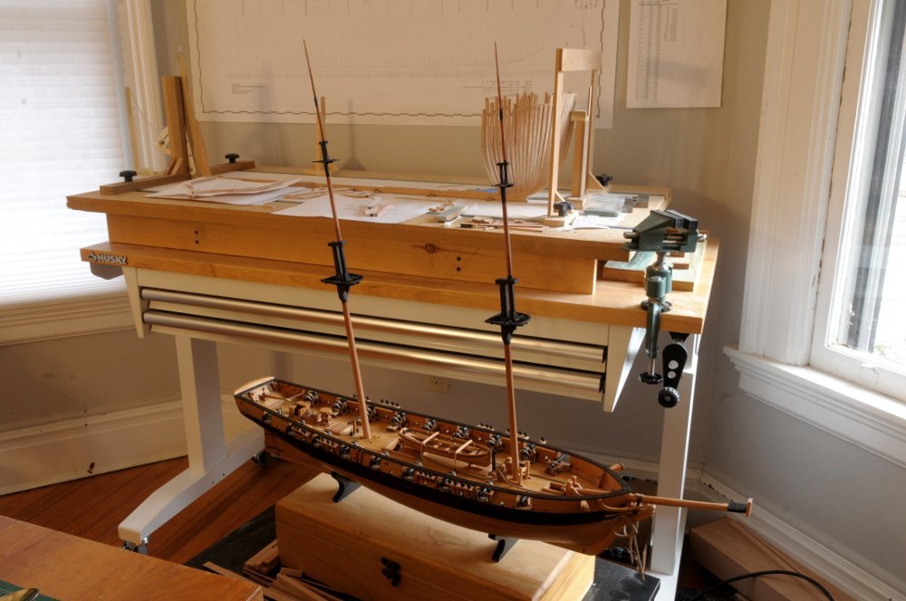
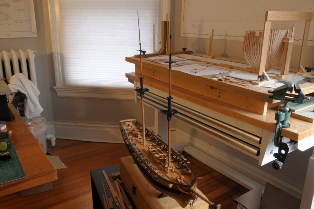
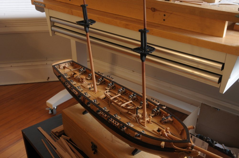
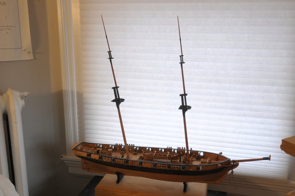
The masts have all been shaped, and fid holes and sheave holes cut into them in various places also. I blackened using my usual method (shown a few times earlier in this log), and here they are-- They are not completely finished. Tung oil finish is only partly applied, as part of the procedure to minimize bleed of the staining. I need to attach some eyebolts to the caps; and the shroud deadeyes and some blocks to the tops, but they can finally be temporarily assembled to see how they look-- And on the ship-- Next will be finishing those parts I mentioned earlier, and checking the deck to see if there's anything else that should be done before starting the standing rigging. Also making the rest of the bowsprit, and the trymast that attaches to the aft side of the mainmast. And I'm sure I'll discover additional things that should be done before the stays and shrouds go on! All for now, Ron
-
What kind, brand and where do you buy your end mills?
rlb replied to rlb's topic in Modeling tools and Workshop Equipment
Thanks so much, wefalck, and Toolmaker, for providing some guidance to a beginner. I have messaged with No Idea, and between all of you, I think you have given me the info I was seeking. For anyone following along, the key points for square end cutters for use in wood, as I have learned are: If unspecified most cutters are upcut, which is better for this use. 2 flute cutters are best, with fishtail ends (vs flat ends) even better. High rpm's are important. Uncoated, carbide cutters are fine. Thanks again, Ron
