


Dziadeczek
-
Posts
596 -
Joined
-
Last visited
Reputation Activity
-

 Dziadeczek got a reaction from mtaylor in Serving the line (shrouds)
If you do a lot of serving, it pays to fashion from scraps of brass a small device, that is suspended under the served rope and contains a spool of thread for serving, is moving along the rope while serving it simultaneously. A sort of, small variation on the so called, bow string server, used in archery.
I made one long time ago and it works perfectly every time. I also made a long(er) serving machine - mine is 2.5 ft long and powered with a DC motor, so the entire process of serving is fully automated, hands free, and the serving is very even and tight along the entire length of the rope.
Here is one of the served stays for my model of the French 74 gun ship 1:48.
-
 Dziadeczek got a reaction from BETAQDAVE in Serving the line (shrouds)
If you do a lot of serving, it pays to fashion from scraps of brass a small device, that is suspended under the served rope and contains a spool of thread for serving, is moving along the rope while serving it simultaneously. A sort of, small variation on the so called, bow string server, used in archery.
I made one long time ago and it works perfectly every time. I also made a long(er) serving machine - mine is 2.5 ft long and powered with a DC motor, so the entire process of serving is fully automated, hands free, and the serving is very even and tight along the entire length of the rope.
Here is one of the served stays for my model of the French 74 gun ship 1:48.
-
 Dziadeczek got a reaction from DaveBaxt in Serving the line (shrouds)
If you do a lot of serving, it pays to fashion from scraps of brass a small device, that is suspended under the served rope and contains a spool of thread for serving, is moving along the rope while serving it simultaneously. A sort of, small variation on the so called, bow string server, used in archery.
I made one long time ago and it works perfectly every time. I also made a long(er) serving machine - mine is 2.5 ft long and powered with a DC motor, so the entire process of serving is fully automated, hands free, and the serving is very even and tight along the entire length of the rope.
Here is one of the served stays for my model of the French 74 gun ship 1:48.
-
 Dziadeczek got a reaction from wefalck in Serving the line (shrouds)
If you do a lot of serving, it pays to fashion from scraps of brass a small device, that is suspended under the served rope and contains a spool of thread for serving, is moving along the rope while serving it simultaneously. A sort of, small variation on the so called, bow string server, used in archery.
I made one long time ago and it works perfectly every time. I also made a long(er) serving machine - mine is 2.5 ft long and powered with a DC motor, so the entire process of serving is fully automated, hands free, and the serving is very even and tight along the entire length of the rope.
Here is one of the served stays for my model of the French 74 gun ship 1:48.
-
.thumb.jpg.62d1d69fed1f32364417cb1f9cdeb009.jpg) Dziadeczek got a reaction from WalrusGuy in Serving the line (shrouds)
Dziadeczek got a reaction from WalrusGuy in Serving the line (shrouds)
If you do a lot of serving, it pays to fashion from scraps of brass a small device, that is suspended under the served rope and contains a spool of thread for serving, is moving along the rope while serving it simultaneously. A sort of, small variation on the so called, bow string server, used in archery.
I made one long time ago and it works perfectly every time. I also made a long(er) serving machine - mine is 2.5 ft long and powered with a DC motor, so the entire process of serving is fully automated, hands free, and the serving is very even and tight along the entire length of the rope.
Here is one of the served stays for my model of the French 74 gun ship 1:48.
-
 Dziadeczek got a reaction from Kusawa2000 in Serving the line (shrouds)
If you do a lot of serving, it pays to fashion from scraps of brass a small device, that is suspended under the served rope and contains a spool of thread for serving, is moving along the rope while serving it simultaneously. A sort of, small variation on the so called, bow string server, used in archery.
I made one long time ago and it works perfectly every time. I also made a long(er) serving machine - mine is 2.5 ft long and powered with a DC motor, so the entire process of serving is fully automated, hands free, and the serving is very even and tight along the entire length of the rope.
Here is one of the served stays for my model of the French 74 gun ship 1:48.
-
 Dziadeczek got a reaction from VTHokiEE in Serving the line (shrouds)
If you do a lot of serving, it pays to fashion from scraps of brass a small device, that is suspended under the served rope and contains a spool of thread for serving, is moving along the rope while serving it simultaneously. A sort of, small variation on the so called, bow string server, used in archery.
I made one long time ago and it works perfectly every time. I also made a long(er) serving machine - mine is 2.5 ft long and powered with a DC motor, so the entire process of serving is fully automated, hands free, and the serving is very even and tight along the entire length of the rope.
Here is one of the served stays for my model of the French 74 gun ship 1:48.
-
 Dziadeczek reacted to Kusawa2000 in HMS Agamemnon by Kusawa2000 (Mike Draper) - FINISHED - Caldercraft - Slightly modified version
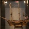
Everyone: Its been a while but I finally have a sail on the ole Agamemnon. Its been a lot of trial and error but I have the lower fore course. Still have a lot of fiddling to do but I want to get the rest of the sails on the foremast rigged before I start trimming lines. In any case, its a good feeling to finally have made some progress
-
.thumb.jpeg.fc5d633a7b34428fcf19419a73d56d55.jpeg) Dziadeczek got a reaction from EricWilliamMarshall in La Créole 1827 by archjofo - Scale 1/48 - French corvette
Dziadeczek got a reaction from EricWilliamMarshall in La Créole 1827 by archjofo - Scale 1/48 - French corvette
Sorry to intrude into your conversation, but the server (spool traveler - as you called it) isn't supposed to be supported in any way by this steel rod below. At least in my instance, mine hungs freely under the rope being served, suspended only by the serving thread. The gravity alone provides enough torsion and tension for serving. If the server tries to rotate around the rope, it means that there is too much tension on the thread, and you have to very slightly loosen up the screw on the bobbin so that it moves a bit easier.
Perhaps the pics from Johann were taken from up and showed erroneously in perspective that the bobbin somewhat rests on the rod?
Or maybe his does rest on the rod?
I would like however to know, how he did the worming on that rope.
-
Dziadeczek got a reaction from EricWilliamMarshall in La Créole 1827 by archjofo - Scale 1/48 - French corvette
You have to explore the possibilities that are offered by people who are into archery. Namely, they use the so called "bow string server" which travels along the served line while serving it at the same time. Please google "bow string server" and select "images" and you'll see many potential solutions.
They typically serve the line for a bow, which is a bit thicker then most of your miniature ropes for shipmodeling, so, if you want to obtain a commercially available gadget, you have to choose a possibly smaller one typically available for archery. Or, make one by yourself from parts which are typically available around your house/workshop. The solutions are endless...
The beauty of such a server is that it requires no, or very little attention, while serving your lines. It hungs suspended from your rope and its weight and tension controlled by the screw (next to a spool with thread), controls how tight is your serving. (Initial setup is therefore required) .
Once you start your serving process, you can literally make yourself a cup of coffee and drink it while observing the action of serving (provided that your serving machine is mechanically powered (electric DC motor) and you are serving a long enough piece of a rope). The server, while serving your rope, WILL AUTOMATICALLY MOVE ALONG THE ROPE without your intervention whatsoever. You can even install a device that will shut off the power to the motor when the serving reaches the end of the rope, so that you don't have to watch the process.
Many years ago I made a simple device for serving - see attachments. It works perfectly for most of my ropes. Bigger (thicker) ropes will require a bigger server, naturally.
-
Dziadeczek got a reaction from mtaylor in Papegojan 1627 by mati - FINISHED - 1/48
Outstanding model and the attention to detail! Congratulations!!!
Can you share the secret, how did you achieve the dark grooves in your rigging? Staining the lines and immediately rubbing it off, perhaps?
Thomas
-
Dziadeczek reacted to mati in Papegojan 1627 by mati - FINISHED - 1/48
Hi All,
This time... finally some rigging 🍻
Side tackle and garnet tackle.
For the time being garnet tackle pendant and guy will be removed as it will go over the shrouds.
Obviously running rigging is not yet fixed permanently. It will be necessary with shrouds and stays to do some tension adjustments.
Garnet tackle and side tackle were used for loading purposes and also for some heavy job on board... lifting of heavy ropes, cannons, etc...
When not in used side tackle were not rigged and garnet tackle pendant and guy were secured.
Next step... shrouds.
Cheers,
Matt
-

-
Dziadeczek got a reaction from EricWilliamMarshall in Rope Making Basics
Mike,
The fewer strands are in your rope, the thinner the rope is. For instance, two stranded rope is slightly thinner then three stranded one, which in turn is slightly thinner than four stranded rope. Of course, some of the bigger (thicker ) ropes on real ships were four stranded ropes like, like anchor ropes, some stays, etc.
If you can replace inner core in your model rope from another strand (thread) to a copper wire (some ropewalks let you do it), you can later on manuallly form your rope to look more "authentic" looking, let's say a sagging, loose piece rather than laying stiff and straight on a model, as miniature ropes tend to do.
Also, whether right hand twist or left hand twist, depends on what type of rope you intend it to represent. Some types of ropes were right handed and other left handed on real ships. If you care to do it more authentically looking, pay attention! If not, ignore it and make all of them the same. It is your model! Have fun!
-
-
Dziadeczek got a reaction from mtaylor in 4 butt shift system on the hull
The Victory book by McGovan has a nice pic on the planking expansion.
-
 Dziadeczek got a reaction from michael101 in 4 butt shift system on the hull
The Victory book by McGovan has a nice pic on the planking expansion.
-
-

-
 Dziadeczek got a reaction from Bob Cleek in Are there any decent clamps?
After all these years I found out, that if I properly spill and heat bend my planks off the model, I don't need any planking clamps afterwards. The planks should lay on the bulkheads almost perfectly, you only need to gently press them in place. For this I use ordinary sewing pins, sometimes those with colored heads. I gently tap them into a bulkhead with a small jewelry hammer, maybe two or three times - just enough to hold them in there, placing the tip of a pin directly under the edge of the plank, NOT THROUGH IT! That way, I don't end up with a hole in the plank, but rather a small hole In the bulkhead (which will be covered by planking anyway, so it won't be visible).
This is my old model of the MS Rattlesnake, showing this process.
-
 Dziadeczek got a reaction from Canute in Are there any decent clamps?
After all these years I found out, that if I properly spill and heat bend my planks off the model, I don't need any planking clamps afterwards. The planks should lay on the bulkheads almost perfectly, you only need to gently press them in place. For this I use ordinary sewing pins, sometimes those with colored heads. I gently tap them into a bulkhead with a small jewelry hammer, maybe two or three times - just enough to hold them in there, placing the tip of a pin directly under the edge of the plank, NOT THROUGH IT! That way, I don't end up with a hole in the plank, but rather a small hole In the bulkhead (which will be covered by planking anyway, so it won't be visible).
This is my old model of the MS Rattlesnake, showing this process.
-
 Dziadeczek got a reaction from bolin in Are there any decent clamps?
After all these years I found out, that if I properly spill and heat bend my planks off the model, I don't need any planking clamps afterwards. The planks should lay on the bulkheads almost perfectly, you only need to gently press them in place. For this I use ordinary sewing pins, sometimes those with colored heads. I gently tap them into a bulkhead with a small jewelry hammer, maybe two or three times - just enough to hold them in there, placing the tip of a pin directly under the edge of the plank, NOT THROUGH IT! That way, I don't end up with a hole in the plank, but rather a small hole In the bulkhead (which will be covered by planking anyway, so it won't be visible).
This is my old model of the MS Rattlesnake, showing this process.
-
Dziadeczek got a reaction from mtaylor in Are there any decent clamps?
After all these years I found out, that if I properly spill and heat bend my planks off the model, I don't need any planking clamps afterwards. The planks should lay on the bulkheads almost perfectly, you only need to gently press them in place. For this I use ordinary sewing pins, sometimes those with colored heads. I gently tap them into a bulkhead with a small jewelry hammer, maybe two or three times - just enough to hold them in there, placing the tip of a pin directly under the edge of the plank, NOT THROUGH IT! That way, I don't end up with a hole in the plank, but rather a small hole In the bulkhead (which will be covered by planking anyway, so it won't be visible).
This is my old model of the MS Rattlesnake, showing this process.
-
 Dziadeczek got a reaction from druxey in Are there any decent clamps?
After all these years I found out, that if I properly spill and heat bend my planks off the model, I don't need any planking clamps afterwards. The planks should lay on the bulkheads almost perfectly, you only need to gently press them in place. For this I use ordinary sewing pins, sometimes those with colored heads. I gently tap them into a bulkhead with a small jewelry hammer, maybe two or three times - just enough to hold them in there, placing the tip of a pin directly under the edge of the plank, NOT THROUGH IT! That way, I don't end up with a hole in the plank, but rather a small hole In the bulkhead (which will be covered by planking anyway, so it won't be visible).
This is my old model of the MS Rattlesnake, showing this process.
-
 Dziadeczek got a reaction from Duanelaker in Youtube photoetching tutorial
For more info on the topic, check out this link:
Photo Etching - do it yourself - Metal Work, Soldering and Metal Fittings - Model Ship World™
I did not use the Micro Mark kit, since my pieces had to be way bigger - hence I had to build my own UV exposure lamp, get a bigger laminator and a bigger developing tank. I based the entire procedure on the very informative tutorial by Gene Berger (link included in the above mentioned thread), so I used different chemicals and exposure parameters than those proposed in the video. There are many ways to "skin the cat", one has to choose what is better for him and what is available in his area.
This is definitely doable at home, but it is a learning curve - one has to determine all variables based on one's trials and errors.
Do not expect to do it once and end up with gorgeous results! Patience!!!
Have fun...