


PAnderson
-
Posts
117 -
Joined
-
Last visited
Content Type
Profiles
Forums
Gallery
Events
Posts posted by PAnderson
-
-
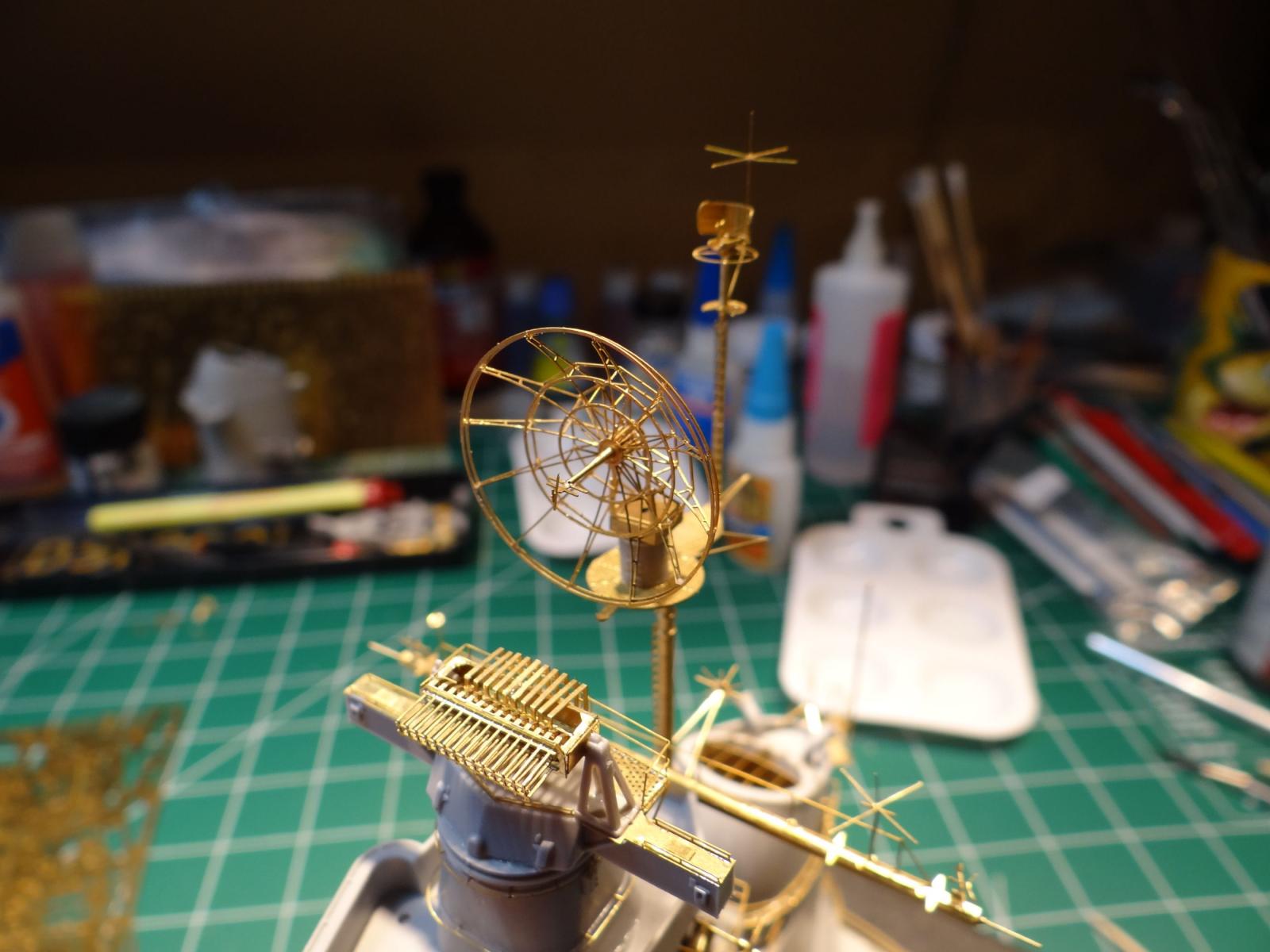
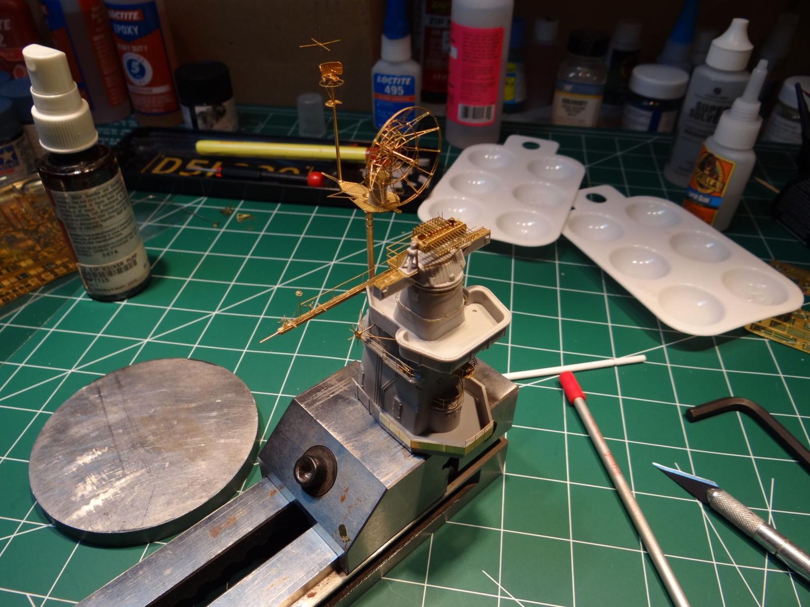
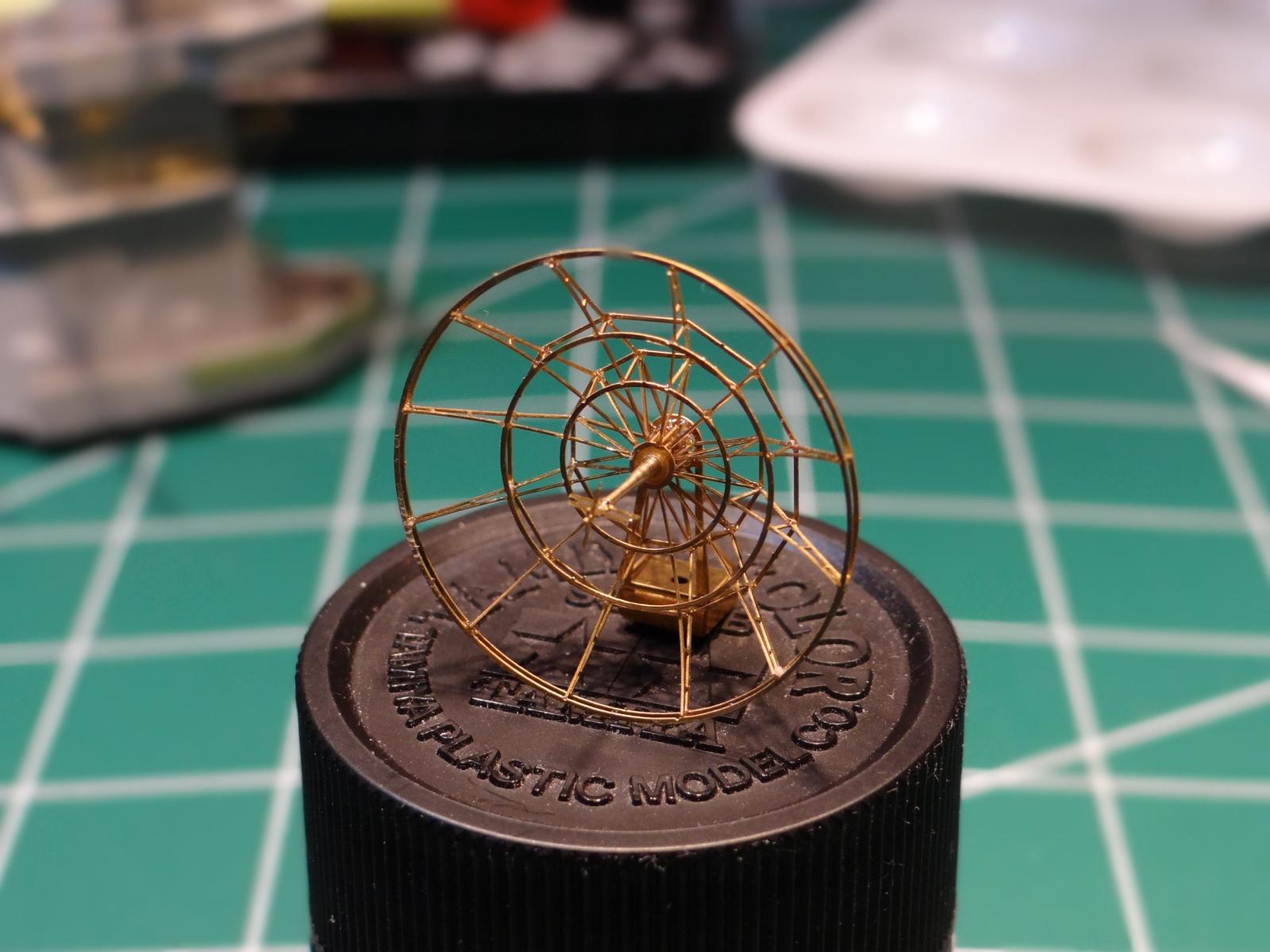
One more question about glueing up PE. What type of glue do you use on multi-part PE builds like that delicate radar dish? Do you use the same glue to attach the PE to the plastic model?
The PE is all glued with thin CA and applied with those fork shaped applicators. You can buy them at Micro-Mark. Very little glue is needed. Actually, the least amount is the best with CA. I read that a drop per square inch gives the best bond. Too much and the bond gets brittle. I also used medium CA for areas that had a wider surface area to glue. Yes, use CA to bond PE to plastic.
I hope I was helpful,
Paul
-
Hi Paul,
Amazing PE work!!!
Mind if I ask you a technique question re painting? After I finish my current 1/192 DD build I'm going to try my hand using an airbrush for the first time on a 1/350 resin kit. My question has to do with painting decks vs bulkheads and when to put on the PE.
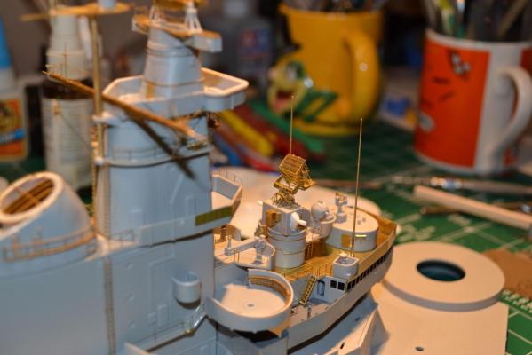
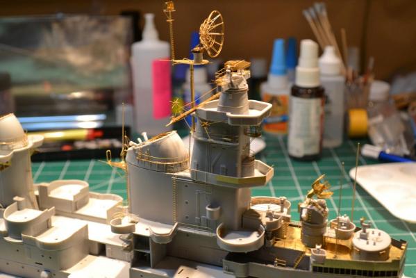
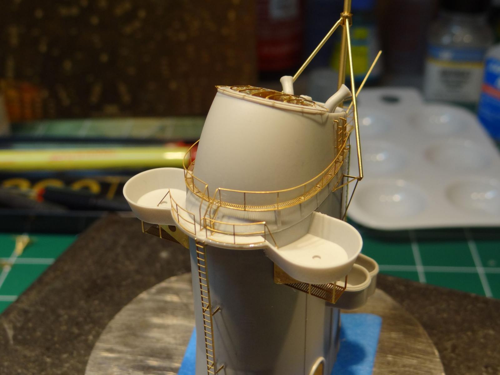
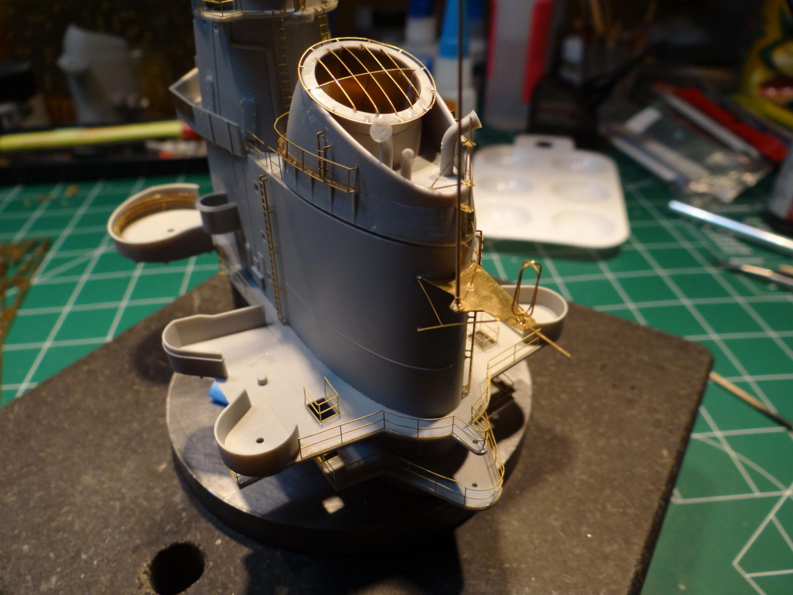
Taking your superstructure area just forward of the forward funnel as an example: you have several areas where you have PE railings around the deck edges. Do you plan to paint the deck a darker color than the vertical surfaces? If so will you airbrush everything haze grey and then go back an brush paint the decks or will you paint the decks first, mask them, and then spray the vertical surfaces?
Sorry if these seem like dumb questions but I have seen a lot of builds (including "how-to" books) where an unpainted model has a ton of PE on it and the next photo in the sequence shows everything painted, including a different paint color on the decks yet it is never explained how it all happened.
thanks for any help.
Tim,
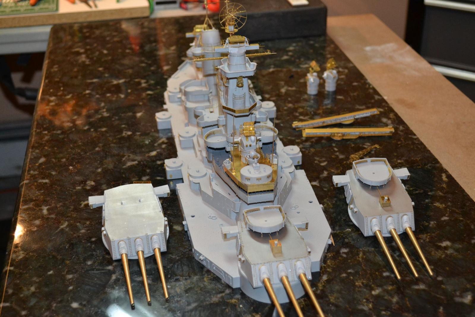
Thanks for the like. None of the sub assemblies are glued on yet. Everything will be painted prior to gluing. There is still parts of the wood deck that need to be applied. They will go on after painting and everything is ship shape and ready to go. This ship is being done as she was in Tokyo Bay for the signing of the surrender papers. She was newly painted haze grey above the main deck. Kind of easy except a lot of pre planning is needed.
But, she is in dry dock at the moment. Still a ton of PE goes on and I am arguing with myself whether or not to use it all or use some of the kit supplied parts (plastic). Some of it is not bad. Just asking myself how much is enough.
Paul
- Canute, Ryland Craze and mtaylor
-
 3
3
-
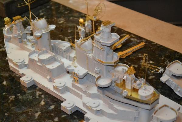
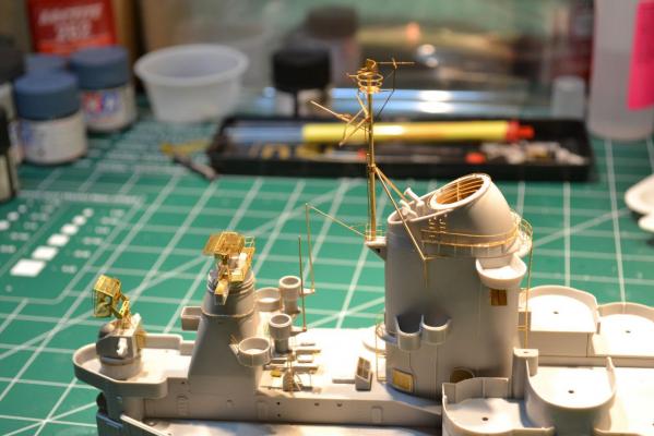
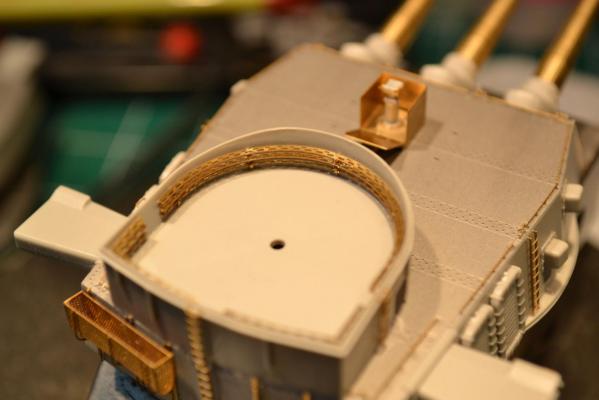
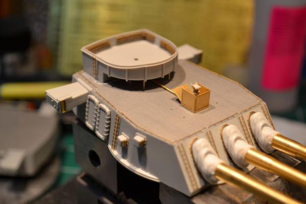
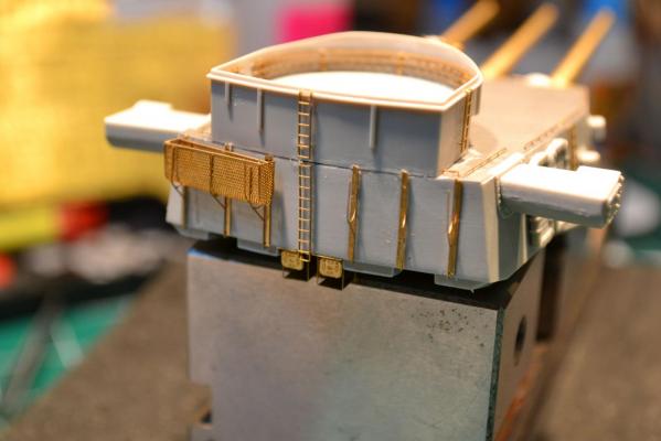
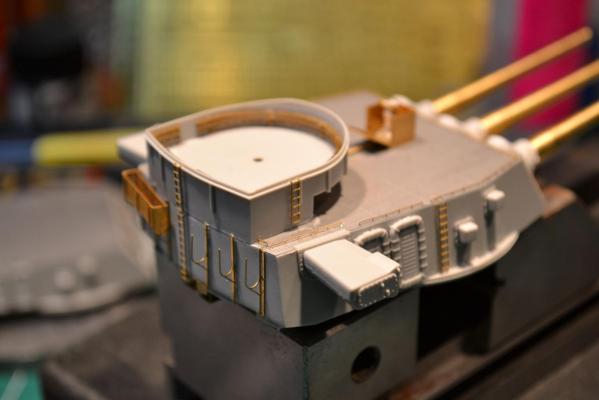
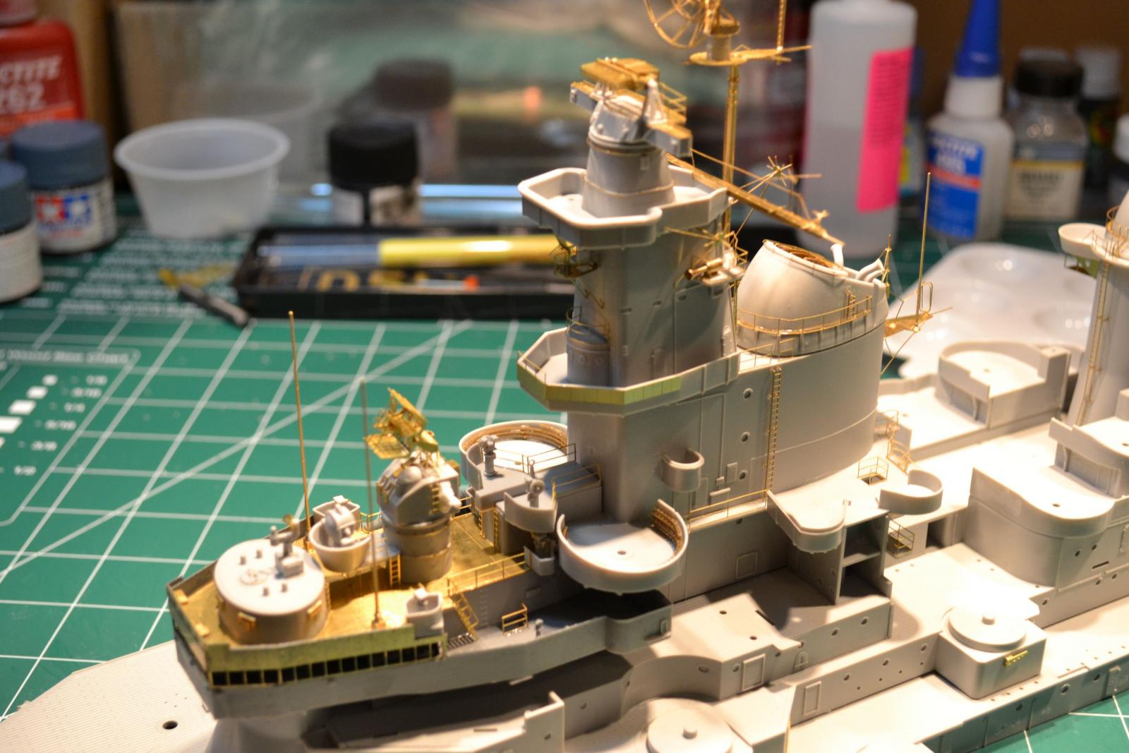
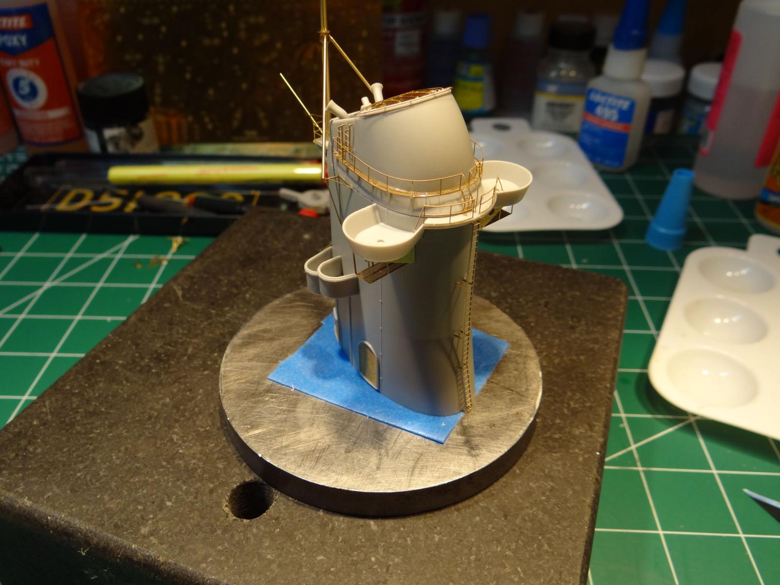
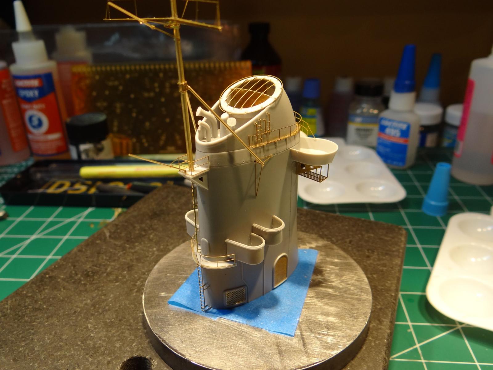
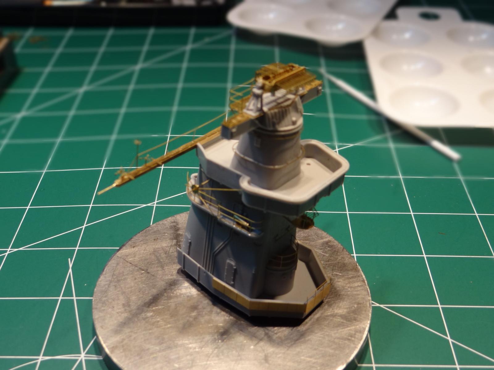
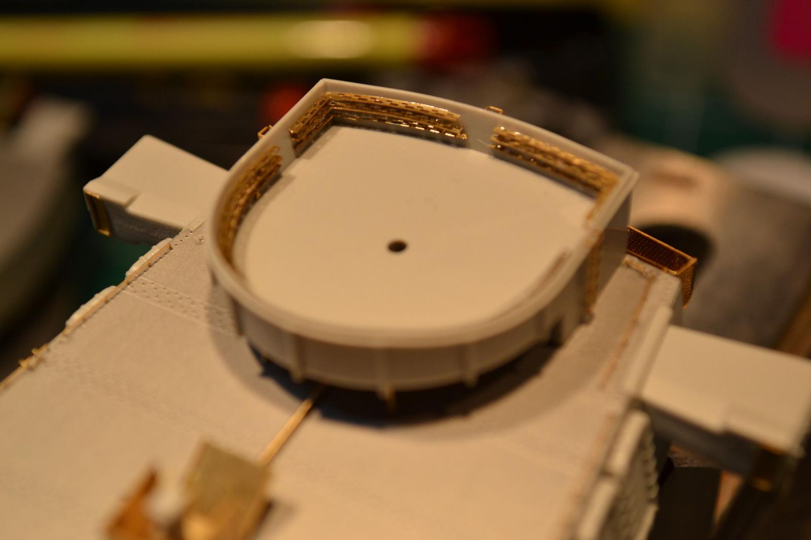
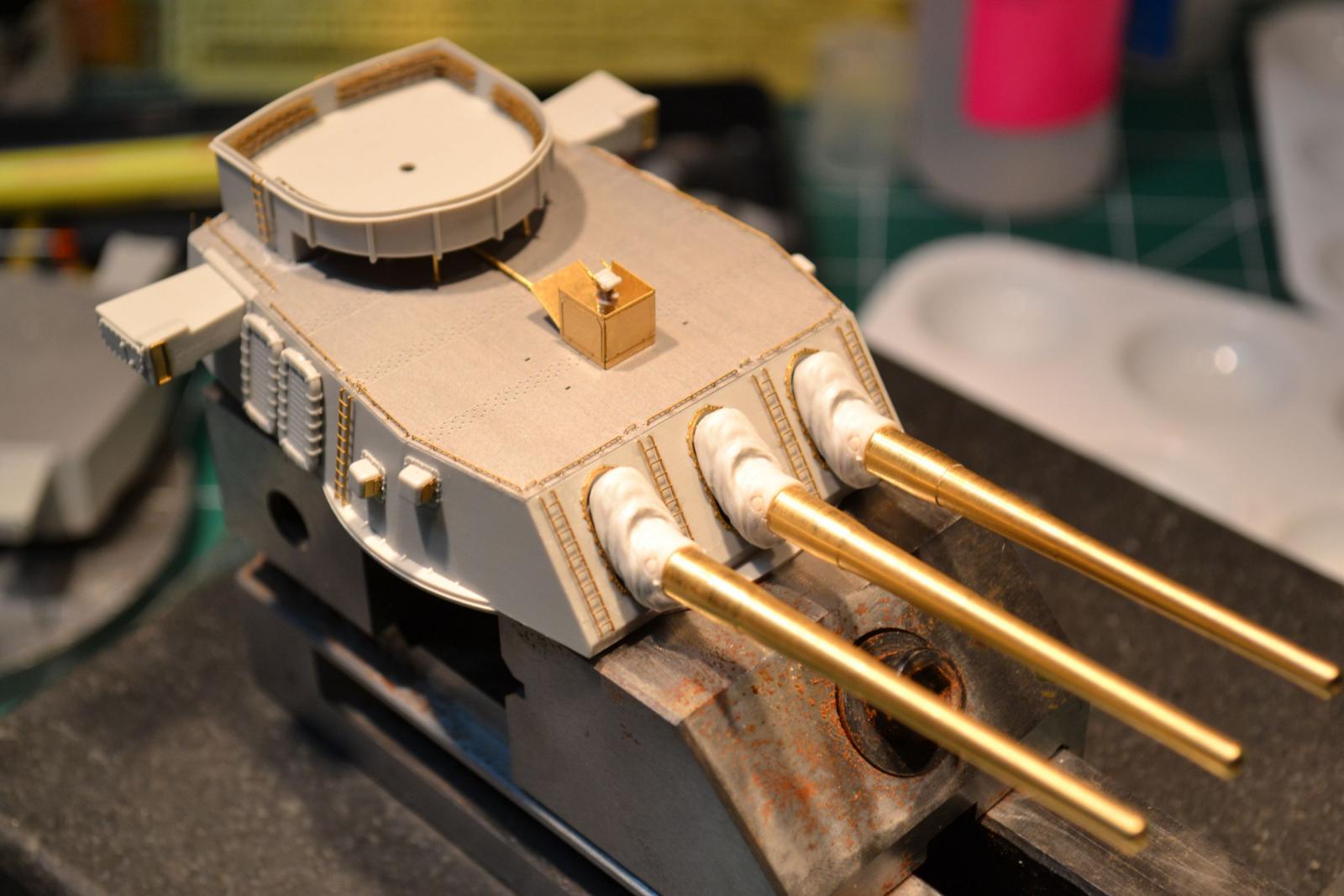
And finally, here is the superstructure assembled but not glued yet. Painting would be next, before assembling to the deck.
This ship will commence again soon. First, I need to find out how to safely remove the old wood deck without too much damage. It doesn't need to be perfect because another wood deck will more carefully installed.
Paul


- mtaylor, harvey1847, Ryland Craze and 6 others
-
9
-
-
-
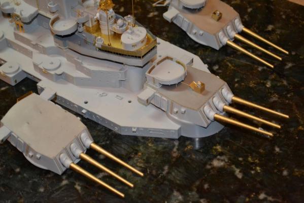
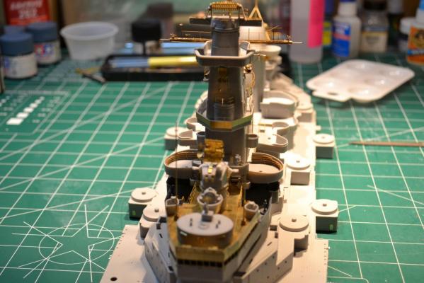
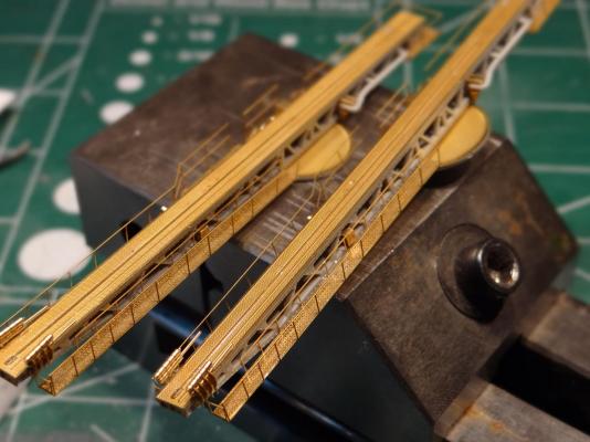
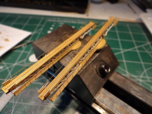
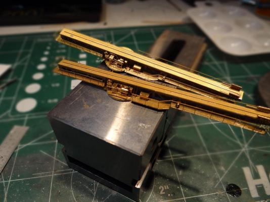
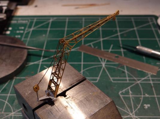
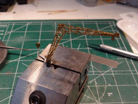
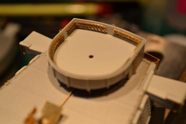
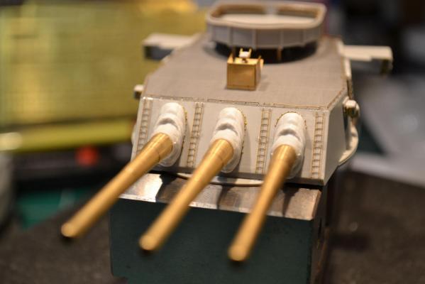
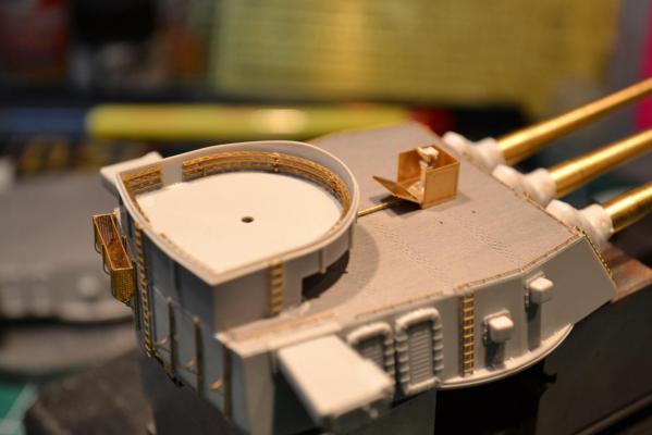
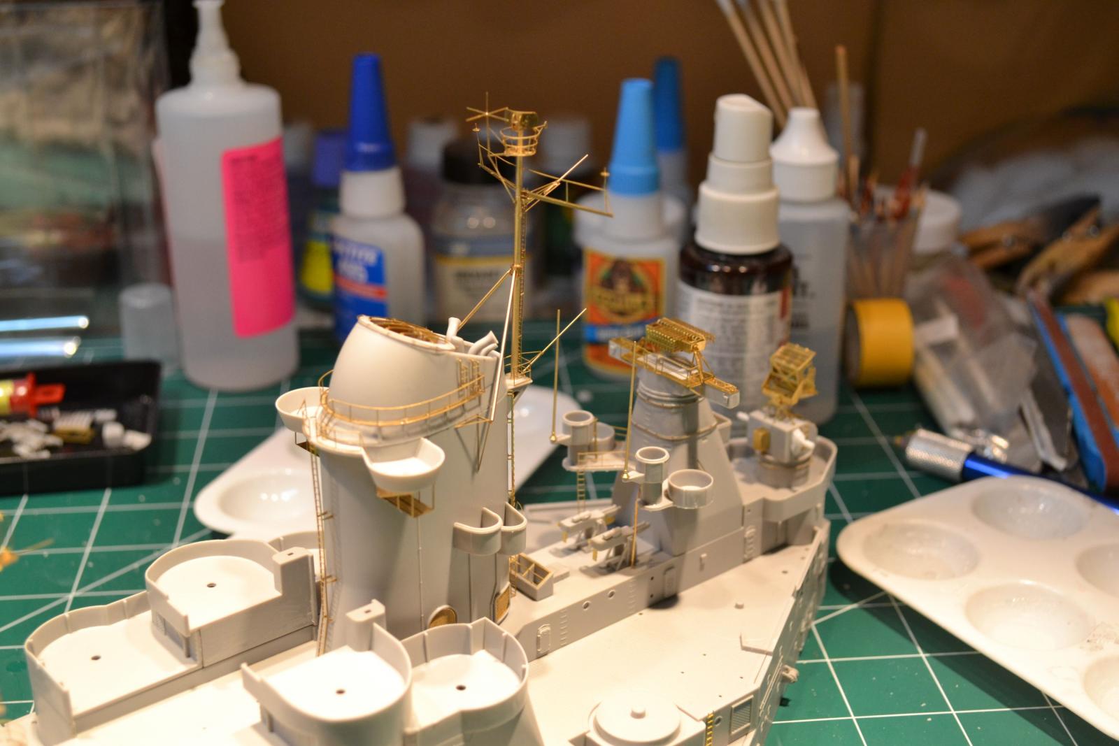
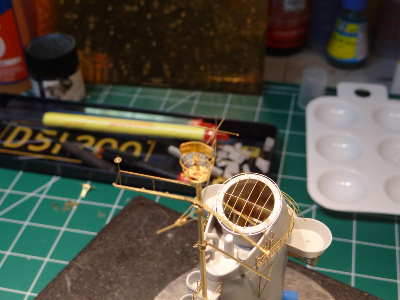
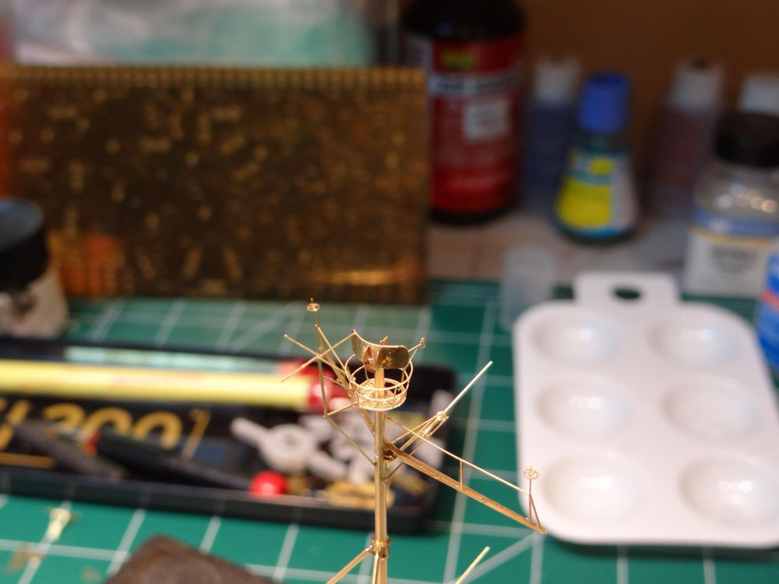
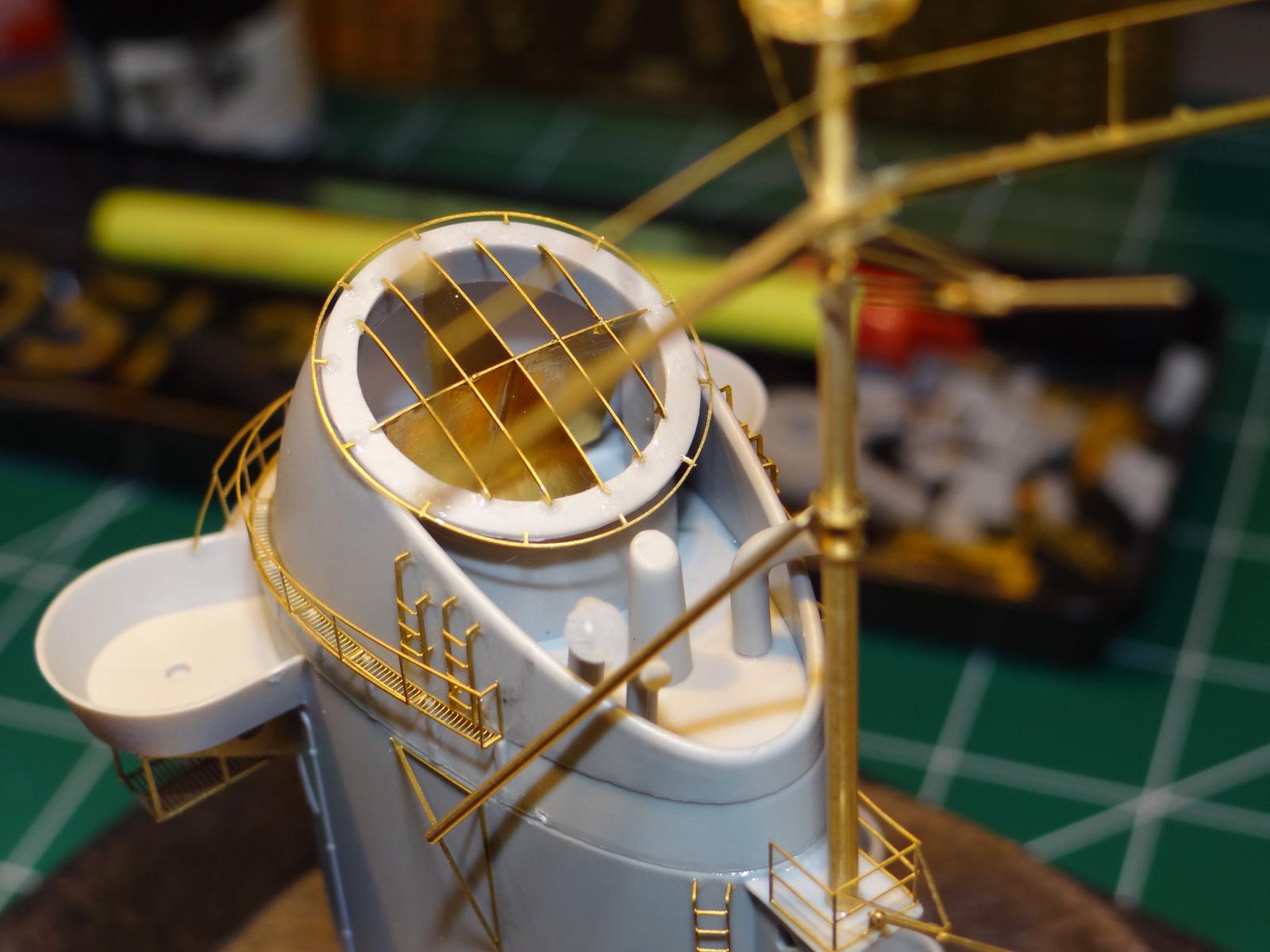
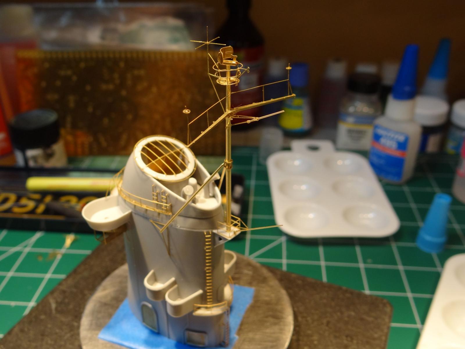
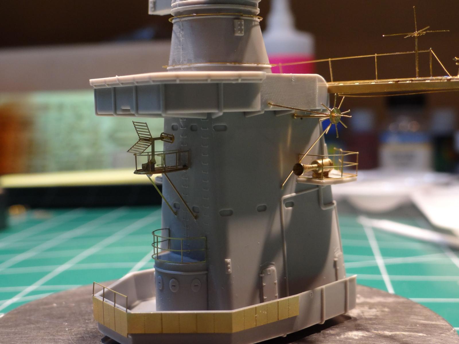
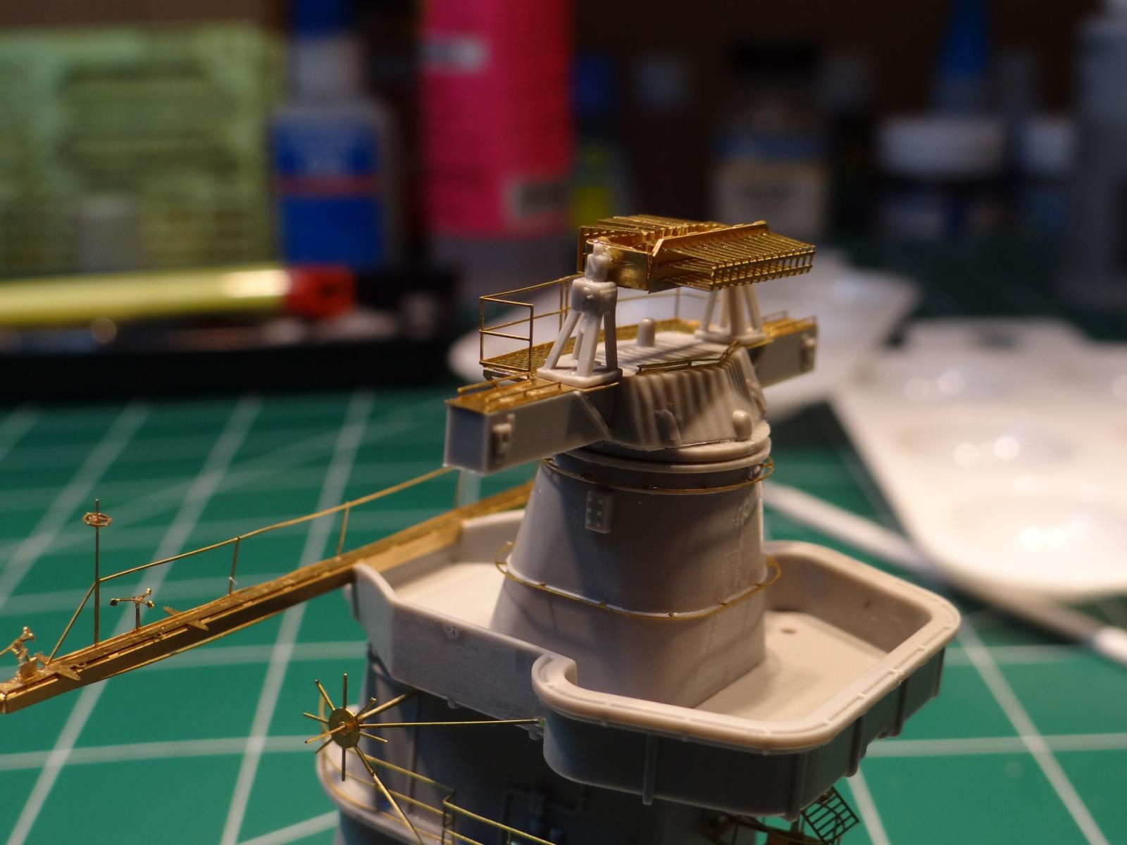
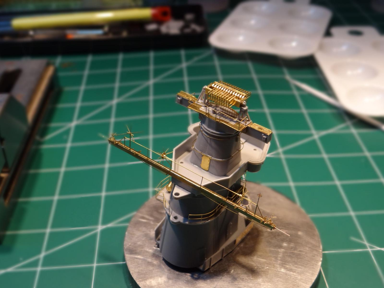
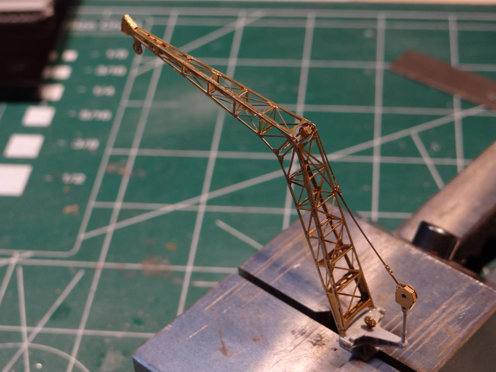
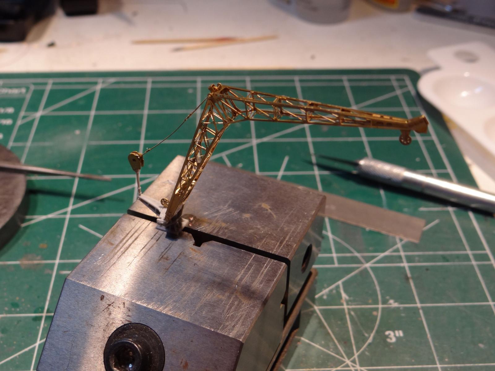
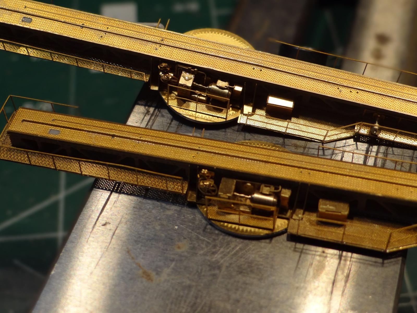
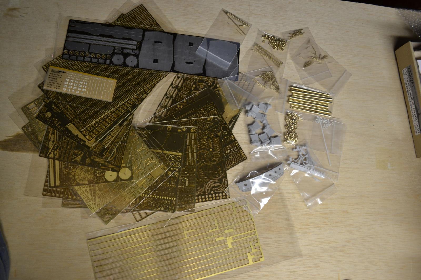
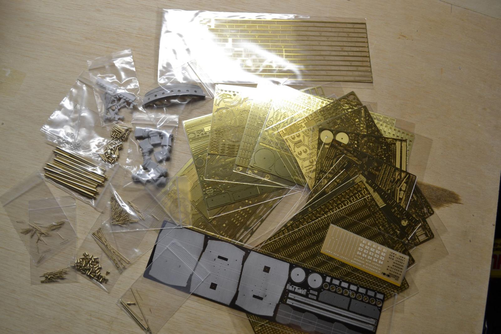
More of the photo etch work.


- mtaylor, Canute, Ryland Craze and 2 others
-
5
-
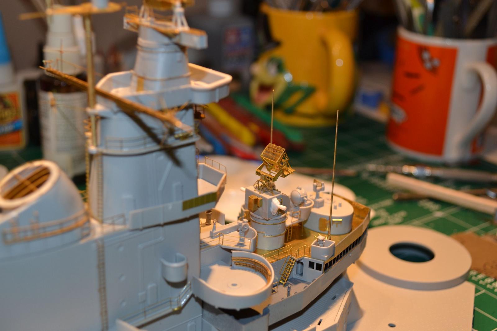
The photo etch is awesome but tiring, with what little I have of dexterity left in these old bones. I had fun doing it though. What I lack in dexterity I must make up for in patience.

- schooner, Captain Slog, justsayrow and 3 others
-
6
-
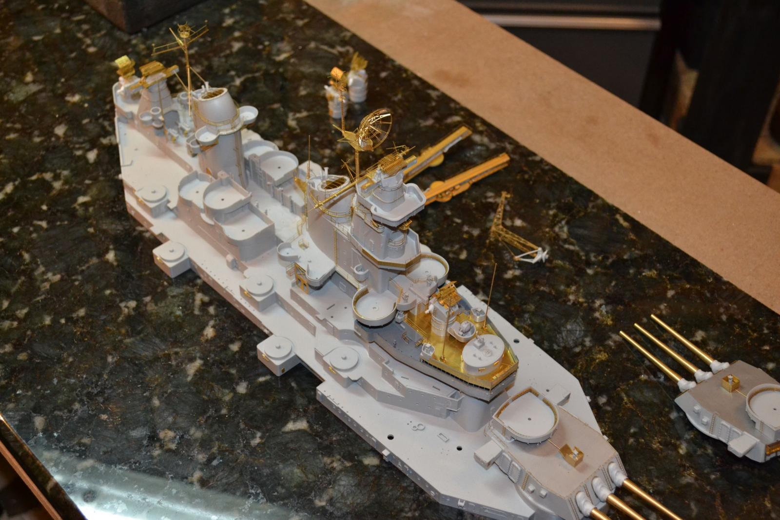
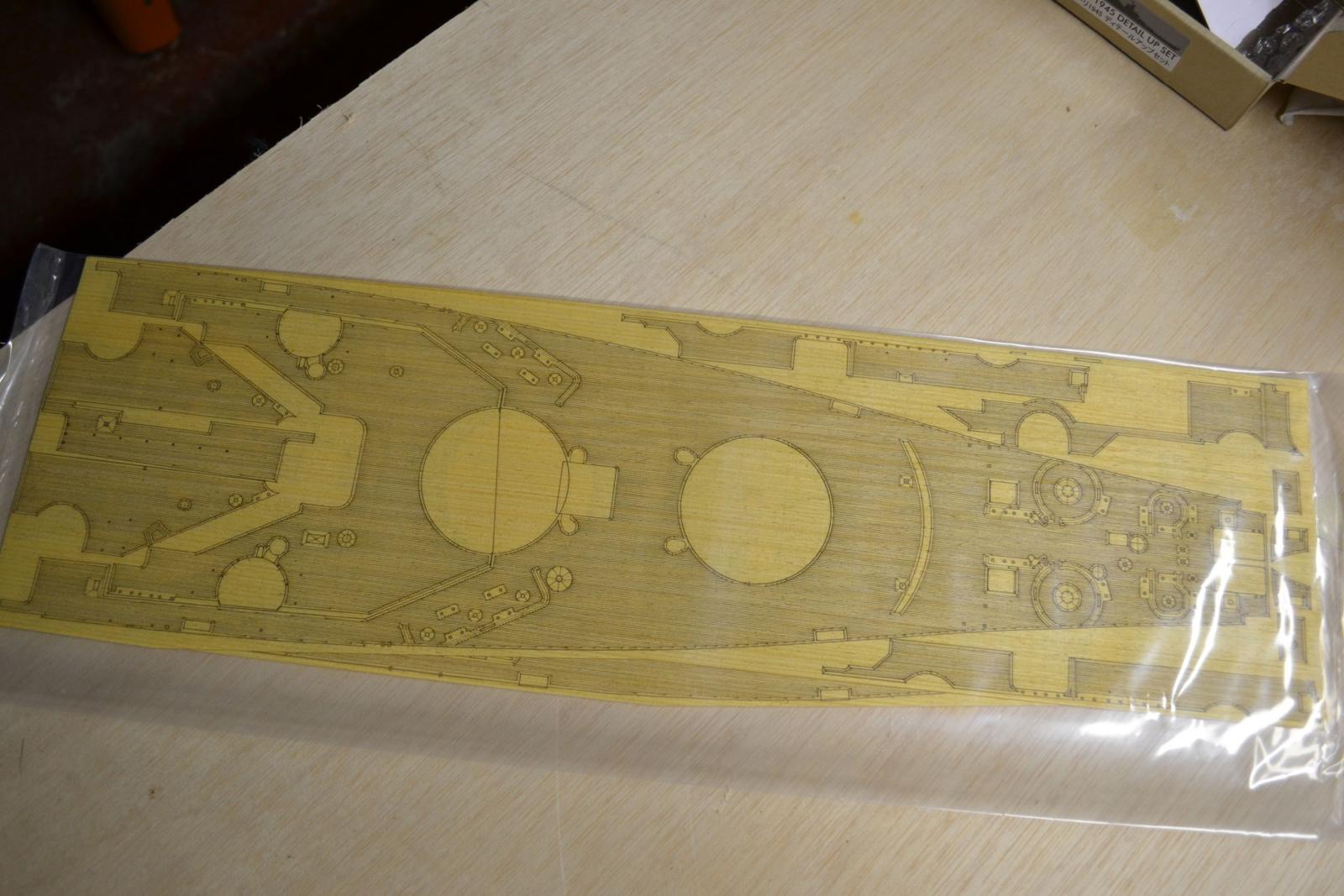
Hello, I thought I would post my progress of this great ship from WW2. I started this over a year ago, before I built mt granddaughters doll house and when I kind of got burned out on plastic. My love of wood kind of took over right about then.
Also, this ship came to a standstill when the wood deck I applied started to delaminate from the plastic deck. Too many attempts to lay it down because of mis-alignment errors and, probably, humidity issues in my workshop. I will have to tear it off and redo it when I get around to starting this ship again.
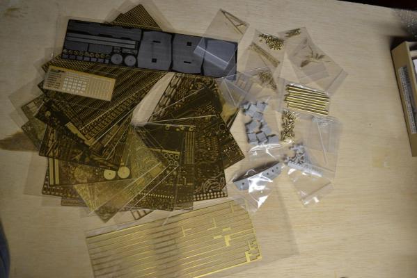
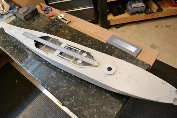
I added the Pontos photo etch set with turned barrels and all kinds of other goodies. Enjoy.
Here is the Pontos set and a couple of pics of the hull for scale.


- Canute, Captain Slog, Ryland Craze and 2 others
-
5
-
-
"Line off the stem against the drawing to ensue you keep the strake ends lined up in the rabbet. I copied the plan onto some card and cut it up to get right in that the area. And I cut a card template to shape the stem, too."
Thanks Ken. Did you do this before or after the keel was attached to the false keel? I hope I'm not too late.

Paul
-
Yeah, me too Ken. I roughed in bulkheads 1,2 and 3 before gluing. Thanks for the like. The fairing looked pretty good but take that with a grain of salt. I tested with a batten but never having faired a hull except for my longboat and one 25 years ago, I have very little idea how good it actually is. I will test again after the frames are on.
Did you have to fair the frames again?
Paul
-
-
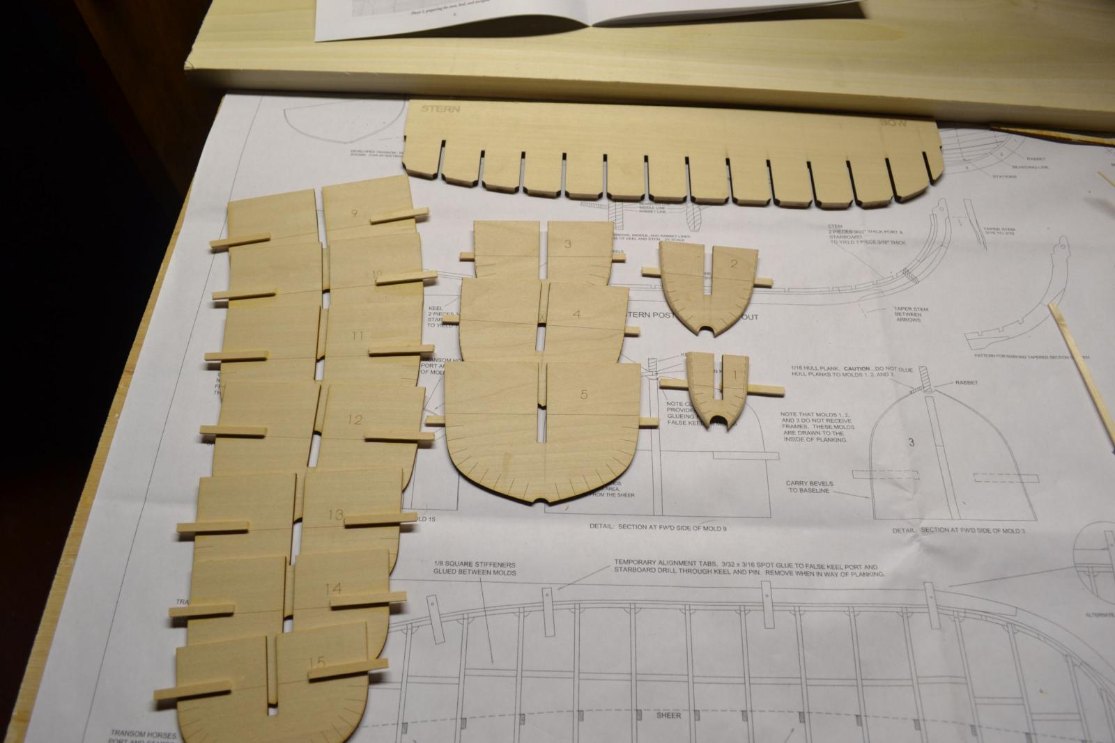
Hello everyone. On the heels of my longboat build, I have started this little gem. So far I have gotten to the point of bending on the frames wet and letting them dry. Haven't done them yet, just pondering this next step. This seems like a big deal since it sets the stage for what comes next, planking.
Planking would be the biggest challenge but since the planks have already been shaped and ready to go. I have found that all of the laser cutting was done really close to size, if not fully to size, it doesn't leave much room for error. So here are the pics so far. I have been through Canutes' build and a couple of others so I hope I can do this justice.
Here the false keel is laid out and the bulkheads. There doesn't seem to be a lot of char. Some discoloration but no "burnt" edges. I'm impressed. So, I sand lightly and leave a hint of discoloration because, like I said, everything seems to be cut really close to finish and I an afraid that if I go to town, some things may not fit or line up later.

Here, the keel parts are finish stained, ready for gluing. It didn't seem like I sanded a lot off where the laser burn was but I had to shim the parts to bring them in line with the plans.
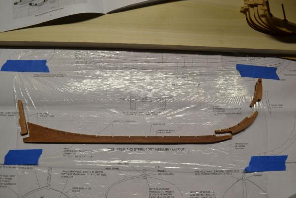
Next, the sheer tabs are on the bulkheads and they are glued in place to the false keel. Next, everything was strengthened with braces.
Next, the glued up keel is on the frame. The rabbet has NOT been cut yet, just to see how everything looks. So far so good.
Lastly for now, the rabbet has been cut. That seemed far easier than I thought it would be. The keel is attached to the frame. The keel tabs were only glued below the keel using CA. I liked this method better than pinning the keel through the tabs. Also, the transom is glued to the keel but not the horses. The first attempt left the transom tilted to one side, maybe from the clamps. I had to remove it using alcahol. I then reglued it using more clamps and placing some blocks under the transom on either side. I built up a set of machinist JO blocks so the transom would not tilt again.

So that is it for now. Next is to cut the frames to length and soak them in boiling water for a while and then start to fit them. I am hoping to get these to fit what was already faired. That seems like a huge task. Two at a time, port and starboard.
Did anyone end up refairing the frames after this step, even a tiny bit. Frames 1, 2 and 3 will be faired after the frames are glued as will the transom. I really wish there was a better way than just crossing my fingers.
Paul

- Canute and CaptainSteve
-
2
-
Eric, she came out absolutely gorgeous. That is some nice work. I really like the simulated caulking, that came out really nice. Now, on to bigger and better things.I agree with Mike, you have some real potential talent and your next project should be great. The Cheerful sounds like a great plan.
Carry on matey,
Paul
-
-
Nice work so far Ken. I just started this boat. I hope you don't mind if I follow your build. I am just getting ready to bend on the frames.
Merry Christmas,
Paul
- mattsayers148, Canute, mtaylor and 3 others
-
6
-
-
-
By industry standards, all materials are cut using a base number called Surface feet per minute. Here is a comparison. Soft steel using HSS cutters are cut around 60-100 SFM. Let's say you are using a 1/4 inch cutter. The formula is SFM X 3.82 divided by the cutter diameter. So 100 SFM X 3.82 / .25 equals 1,528 RPM.
Wood on the other hand is much softer, let's say 500 SFM. So, 500 SFM X 3.82 / .25 equals 7,640 RPM. These are conservative numbers but you see where this is going. No hobby machine (nothing against hobby machines, LOL) will go this high.
Feedrate is RPM X feed per tooth X number of teeth. Above example: 7,640 X .002 X 4 flutes. equals 61 inches per minute. Granted, without a readout on your machine you will never know but 61 IPM is pretty fast.
This is also why you don't need carbide but carbide lasts 100 times longer if it is not abused. Carbide in wood is probably about 1500 SFM, guessing here. I would have to look it up. The above example would be almost 23,000 RPM. 23,000 X .002 X 4 flutes equals 183 IPM. You can't crank a handle that fast.
As your cutter gets smaller, your RPM approaches infinity. A 1/16 cutter would run at about 92,000 RPM and 740 IPM. Ain't gonna happen. Our machines at work won't even do this so we adjust accordingly.
I only use these examples because this is the industry standard in production shops and that is what people would try to attain for efficiency sakes.
Rather unimportant in our little shops but the point is you have to adjust your methods for your capabilities and because the given RPM can't be attained, your feed will be divided accordingly.
The other comments above are correct. It comes down do feel and getting to know your machine, your cutters and the kind of wood you are cutting. I imagine cutting Balsa would give you a heck of a time (too soft) while cutting Oak would be like cutting some soft steel.
Paul
-
-
I'm new to this one Mark. What a beautiful planking job. Seeing work like this is intimidating at best. I could only dream of doing something like this some day.
Paul
- Seventynet, GLakie, mtaylor and 4 others
-
7
-
Hello again. After careful consideration I have decided my next build will be the HMS Bounty Launch by Model Shipways. This will be my third build overall, after the most recent, the 18th Century Long boat. That was a delightful kit and let me hone my skills, even if it was in a small way. This should get me through Christmas and into the new year. Then Maybe I will have the courage to try something more ambitious.
I pulled the Bounty Launch out yesterday after fondling my USF Confederacy all day Saturday. This kit has pre-made planks. This will let me see what a properly spiled and bent plank should look like and let me work it out and learn a few more things. I do understand there will be some conservative fitting and not just slap on a plank. I started the keel last night and got all of the parts laminated and ready to go. This kit, as good as the laser cutting seems to be, seems to laser cut with no room for sanding. I sanded the char off pertinent edges and when I went to fit the stem pieces they no longer fit the plans. Like I said, no room for sanding. I had read one other log and he stated the same issue.
So, question. Would it be a good idea to shim at the scarf joints to build the parts out to fit the plans? The instructions say to explicitly follow the plans. Very well drawn and thought out CAD plans. So, if the parts were cut to CAD data, I could see how this would happen. So, the whole kit seems to be like this and I will need to be very careful.
Question: How much of the char needs to come off to take glue properly? I sanded to just before totally bare wood.
I will start to post pics very soon and I look forward to your ideas. I really like the friendliness and willingness to help on this site. I just wish I could contribute more and give back a little.
OK, I am getting long winded. This is my official start, wish me luck.
Paul
- CaptainSteve, Canute and Julie Mo
-
3
-
Thanks all, I just thought something like this would be easier. The newer pencil "lead" isn't actually lead at all. It's really some kind of polymer. I looked online and it comes in various colors with diameters starting at .3 MM in .1 MM increments up to 1 MM. Just a thought. Thanks for the knowledgeable replies.
Paul
-


 I think you will find a lot of the skills you have can be applied to wood ship kits. Mainly patience and perseverance. Oh, and the use of glue.
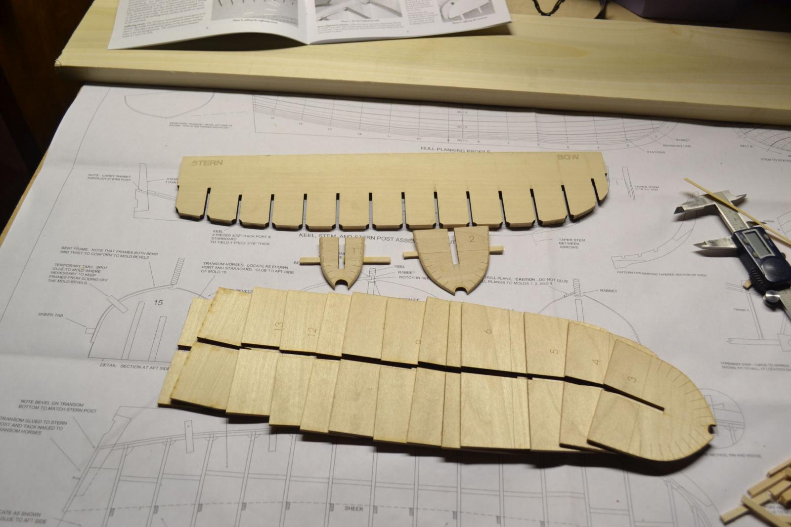


HMS Bounty Launch by PAnderson - Model Shipways
in - Kit build logs for subjects built from 1751 - 1800
Posted
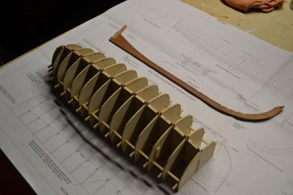
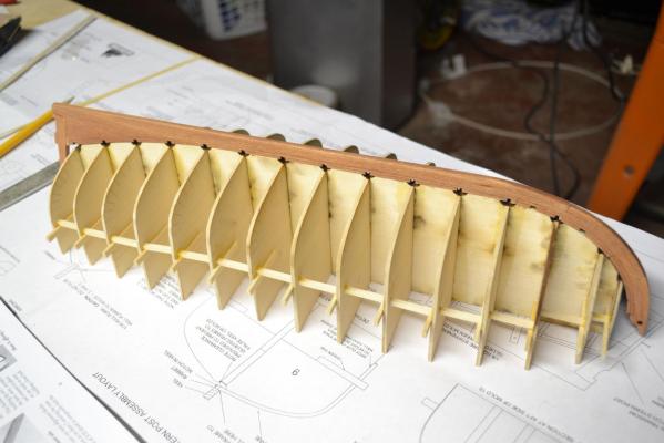
Hello again everyone. I have an update here. You know, some things you just have to work through and consider it a challenge.
I added the frames to the hull mold. But I ran into a little problem. I cut all of the frames to 4 1/2 inches. Then I soaked them in boiling water for a while. I bent and fit 2 frames in the middle of the hull to see how this all worked. I clipped one end under the keel and bent it around and clamped to the bulkhead above the sheer line and let them dry. I am glad I only test fit at this point because when they dried, they shrunk lengthwise and popped out of the keel. I don't remember reading about this on any other logs so I just chalk it up to inexperience and being naive about ship model building. I do remember seeing one log where the builder used frames that went port to starboard in one piece so I decided to do this instead. Rather than throw away the frames I already cut, I will use these for the in between frames. I had enough cherry frame parts to make 9 inch frames and that worked well.
So here is the mold with the frames attached.