


Bob Cleek
-
Posts
3,374 -
Joined
-
Last visited
Reputation Activity
-


-


-
 Bob Cleek got a reaction from rooster in Help painting hull lines
I realize this is probably more than most would ever want to know about painting stripes on models, but it's a subject that doesn't seem to have been addressed here lately and I type faster than a lot of people talk, so here it is.
Aside from the waterline on the X-Y axis, there aren't many straight lines on a seagoing vessel. That said, waterlines can be marked simply by mounting the hull on a flat surface in the "floating" attitude (sometimes there is considerable rake in the keel, particularly in small sailing vessels.) Then take a block of wood of suitable height with a pencil laid on top of it and just run the block around the hull using the pencil laying on the block to mark the waterline. Note that waterlines are not always of constant width. The eye sees the stripe as of a uniform thickness, but, as the stripe is generally on an inclined surface, its width on the hull has to account for that. When you line off a boot stripe with your block and pencil, you'll note that where the hull curves, the top and bottom edges of the stripe will not be parallel. For example, a boot stripe at the tuck of the stern can widen significantly. Another perspective issue is the shape of the hull overall. If a viewer is standing amidships and looking at the boot stripe, the boot stripe at the bow, and perhaps at the stern, will be farther from the viewer's eye than the stripe amidships because the bow, and perhaps the stern, narrow as the hull approaches its ends. For this reason, boot stripes often look better if they are laid out to gradually widen slightly as they approach the bow. This avoids the optical illusion that the boot stripe is narrowing as it runs towards the bow. These adjustments must be done "by eye" when masking the stripes.
As for painting, use a "fine line" masking tape to lay out the lines and paint between the masked areas. Don't use regular house painter's masking tape. The paint will likely run under the paint and make a mess. 3M's Fine Line Tape is a good brand. I believe Tamaya model paints also makes a fine line masking tape. Others have used automotive striping tape, but I've found it's often too thick and out of scale and color selections are limited. A bit of practice is advised before committing to tape and paint the model's hull. The learning curve is short and not steep, but you don't want to mess up the paint job on the model by making that your first try!
Fine line tape can be purchased at art supply stores: https://www.3m.com/3M/en_US/p/d/b40067079/ Buy the 1/4" wide tape and then use regular masking tape on top of that to mask a wider area, if need be. The stuff is not cheap! Thinner is cheaper. About $30.00 a roll! A roll will probably last a lifetime of modeling, though. (Tamaya tape is less expensive, but I don't have any personal experience with it. I've read good reviews of it. Perhaps others can comment. 3M Fine Line is the industry standard for automotive and aircraft painters.)
Be sure to store all masking tape, and especially fine line tape, in zip-lock plastic bags, which retard their drying out and significantly extend their shelf-life to practically forever. Also, never ever lay a roll of any type of masking tape down on its side on your bench top. Always replace it in its zip-lock bag. Laying a roll of tape on its side will cause it to pick up dust and dirt on the side of the tape, which ruins it because the dust and dirt adhering to the edge of the tape will make it impossible to yield a razor sharp line and will permit paint to seep beneath the edge of the tape.
There are other techniques for painting stripes, including using special pin-striping brushes freehand with One Shot sign paint, etc., etc., but the use of fine line tape is the only fool-proof method I know. Even among the pros, it's a rare "fist" who can do it well freehand with a brush.
-
 Bob Cleek got a reaction from AlleyCat in What manufacturers are actually developing new kits?
So very true! This explains the low "kits bought to kits built" ratio of the old kits. The kit companies "sold the sizzle, not the steak," relying on the seductive lure of box cover photos of professionally nearly-scratch-built versions of the kit contents. There remains a solid market for quality kits like Syren's, especially for the discriminating folks just starting out who want to learn to build quality models, but the four-figure-priced Seventeenth Century floating gingerbread castles marketed to the uninitiated without regard to building up repeat business from those who found trying to build them enjoyable are slowly fading away along with the brick and mortar hobby shops that once sold them.
Given all the societal changes wrought by the "digital age," people aren't looking to modeling as a hobby as they once did. I don't see it dying out, but the direction it certainly seems to be going is, IMHO, a positive thing as more and more modelers graduate to scratch building. The commercial end of the market seems to be tending towards parts and materials, and away from boxed kits. Where there seems to be an unfilled market demand today is in the area of plans and instructions to enable potential scratch builders to get over the hump of research, scaling, lofting, and assembly scheduling. Those are among the steepest learning curves in the craft. People want that information spoon-fed to them and will probably pay a good price to buy that if the market (and prices!) for good "how-to-build-it" books are any indication. The good books on the subject have all been in print for decades and demand for new quality titles remains high.
-

-
Bob Cleek reacted to grsjax in help on four kits
The Dusek Knarr in 1:35 scale would make a good basis for the boat in the painting. At a larger scale like 1:12 it would be about the right dimensions and it could be modified to fit the image. Dumas makes some 1:24 kits of ChrisCraft boats.
-
Bob Cleek reacted to rwiederrich in Glory of the Seas 1869 by rwiederrich - FINISHED - 1/96 - medium clipper
Very appreciated Bob. If one looks back at that portion of the build...they can see I expedited the process by creating plate and nail embossed strips....using copper tape. Painting the entire bottom (Over the shiny copper), with a good metallic paint...aided in securing the plates(to themselves and the hull) and transforming the *copper* color to the more realistic color of weathered *Muntz* metal. Which is what the Glory was covered/plated in.
Again, I wish to thank you for your continued support and encouragement. Coming from one with such an experienced background as yourself, is truly motivational.
Rob
-
 Bob Cleek got a reaction from shipman in Glory of the Seas 1869 by rwiederrich - FINISHED - 1/96 - medium clipper
She's certainly coming along nicely, Rob! Great work at such a small scale. I've never seen a better job on a coppered bottom at this scale. You've achieved a compellingly realistic effect. Anybody who undertakes to copper a bottom at this scale should take a close look at your work.
-
 Bob Cleek got a reaction from Gregory in help on four kits
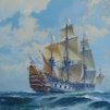
Given the subject matter, I doubt the boat in the famous painting was modeled after any actual boat, but was instead a product of the artist's imagination. There are lots of close up photos online of the vessel. You may wish to take and existing British type and add the stemhead ornamentation of the pictured boat. You will find a wonderful compendium of all similar small craft in Inshore Craft: Traditional Working Vessels of the British Isles, by Basil Greenhill. https://search.yahoo.com/yhs/search/?hspart=pty&hsimp=yhs-browser_wavebrowser¶m2=13a0c110-4dfc-4d18-beab-bcd933c51603¶m3=wav~US~appfocus1~¶m4=d-cp12177353273-lp0-hh6-obgc-wav-vuentp:on-igUHErMLUsbnTbmZQ-ab32-w64-brwsr-ntb-ntp~Chrome~inshore craft of the british Isles~B2D7D7656EB4E5153688637C8FBF7B49~Win10¶m1=20210529&p=inshore craft of the british Isles&type=A1-brwsr-~2021-22~
This book contains lines drawings of many of the entries and these should be sufficient to scratch-build a model at any scale one desires. That will require a certain degree of lofting (drafting,) boatbuilding, woodworking, and modeling knowledge that will require some study given your stated experience level. Unfortunately, the scope of ship model kits is market-driven, and, consequentially, many beautiful craft go unrepresented by kit manufacturers. On the other hand, that's what makes well-done scratch-built models so appreciated and valued.
A "dollhouse scale" 1:12 miniature of the boat in the painting, including the pillows, candles, lantern and such (available from dollhouse supply catalogs) would be quite an interesting model.
It does look like someone has actually built a full-size replica of the boat in the famous painting.
-
 Bob Cleek got a reaction from Roger Pellett in Why do some manufacturers make single plank kits?
Jaager's historical narrative certainly seems accurate. I'd add the theory, as to European manufacturers particularly, that packaging may have been a factor in their favoring plank-on-bulkhead hull construction. Carving hulls out of large, flawless, prime basswood blocks meant that the manufacturer had to pass the cost of all the waste wood to the customer and had to box the solid hulls in larger boxes. The plank-on-bulkhead models eliminated much of the expense of the carving waste and the expensive machinery to do it, reducing the materials to some thin ply, dowels, and strip wood. All of that could be packaged in a smaller flat box that took up much less volume when shipping the European kits to the Americas and meant more available space on retailers' shelves. Those who recall the old Model Shipways "yellow box" solid hull models will be familiar with this difference.
-
 Bob Cleek got a reaction from mtaylor in help on four kits
Given the subject matter, I doubt the boat in the famous painting was modeled after any actual boat, but was instead a product of the artist's imagination. There are lots of close up photos online of the vessel. You may wish to take and existing British type and add the stemhead ornamentation of the pictured boat. You will find a wonderful compendium of all similar small craft in Inshore Craft: Traditional Working Vessels of the British Isles, by Basil Greenhill. https://search.yahoo.com/yhs/search/?hspart=pty&hsimp=yhs-browser_wavebrowser¶m2=13a0c110-4dfc-4d18-beab-bcd933c51603¶m3=wav~US~appfocus1~¶m4=d-cp12177353273-lp0-hh6-obgc-wav-vuentp:on-igUHErMLUsbnTbmZQ-ab32-w64-brwsr-ntb-ntp~Chrome~inshore craft of the british Isles~B2D7D7656EB4E5153688637C8FBF7B49~Win10¶m1=20210529&p=inshore craft of the british Isles&type=A1-brwsr-~2021-22~
This book contains lines drawings of many of the entries and these should be sufficient to scratch-build a model at any scale one desires. That will require a certain degree of lofting (drafting,) boatbuilding, woodworking, and modeling knowledge that will require some study given your stated experience level. Unfortunately, the scope of ship model kits is market-driven, and, consequentially, many beautiful craft go unrepresented by kit manufacturers. On the other hand, that's what makes well-done scratch-built models so appreciated and valued.
A "dollhouse scale" 1:12 miniature of the boat in the painting, including the pillows, candles, lantern and such (available from dollhouse supply catalogs) would be quite an interesting model.
It does look like someone has actually built a full-size replica of the boat in the famous painting.
-
Bob Cleek got a reaction from AlleyCat in Making nice square deck furniture?
Carpenter's and machinist's squares, plus clamps, rubber bands, and a lot of fancy jigs sold for the purpose. You may want to do some YouTube watching about basic carpentry and welding assembly skills to get familiar with the options. https://www.youtube.com/results?search_query=corner+clamps+for+woodworking
Or you can buy store-bought ones:
https://www.micromark.com/Magnetic-Gluing-Jig-10-1-4-Inch-Square
https://www.micromark.com/SET-OF-THREE-ANGLE-PLATES
https://www.micromark.com/Mini-4-Corner-Clamps-1-2-Inch-x-1-2-Inch-to-5-Inch-x-5-Inch-Capacity
While MicroMark has perfected the art of separating modelers from their money, I must say that one item they sell that two set-up tools I've found hugely helpful that they offer are their set of small machinist's squares and their thin-beam square, which makes striking square lines on thin sheet stock a breeze.
https://www.micromark.com/Thin-Beam-Square
https://www.micromark.com/Steel-Machinists-Squares-Set-of-3
These items sometimes come up on MicroMark's "loss leader discount" sales, too.
-
Bob Cleek got a reaction from AlleyCat in Rare complete ship's curves set on eBay
As mentioned, There are 56 curves in the standard Copenhagen curves set. There are many other types of curves, sometimes called "French" curves. These can be found in the old K&E catalogs, one of the more recent ones from the 1930's is found at http://archive.org/stream/pricelistcatalog00keuf#page/231/mode/1up The curves begin at page 231. The Copenhagen curves are at page 234 and following.
The short answer is that, yes, you just have to "try and fit" to get the right curve. The method of use is illustrated below. A curve is defined by a series of "points" (dots) which would in the case of a ship's lines, come from the Table of Offsets, or from measurements from original plans, if one were copying those (usually when changing the scale of the drawing, generally using a pair of proportional dividers.) When the points are laid out, the curves are selected so that they coincide with as many points as possible. sometimes points will be out of position slightly and this indicates that the curve defined by the points is not fair, in which case, the curve will define the fair curve. The curve should "touch" at least three points and preferably more. A French curve is being used to draw the curve in the illustration below. The illustration is of the use of a single French curve. There is no rule against using multiple curves. They are designed to be used that way, such that if they touch at least three points in common, the two curves will define a fair curve when joined at such an overlap. It can be seen that in "A" below, the curve is touching points one through 4. The line would be drawn that far and then, in the illustration, another curve section of the French cure is used to draw points 3, 4, and 5, and in "C" has been manipulated again to draw from point 5 to point 6, and in "D" to draw between 6 and 7, in "E," using the inside of the curve, to draw from point 7 to point 9 and finally in "F" moving the curve again to draw the line from point 9 to point 11, thus drawing the shape intended with a fair curve. In each instance, the curve was moved to see if it fit a number of points. The "eyeballing" to fit the curve isn't as complicated as one might imagine, except in complex curves like the one illustrated below which required six segments to be drawn from six positionings of the curve. Working with lines drawings, it's not too difficult to find a curve, or collection of curves, to meet your needs.
When inking drawings, which in the old days was done with India ink and a "ruling pen," the draftsmen would tape coins or washers to the face of the curves being used so that the edge of the curve was raised slightly above the paper or drafting linen. This space prevented ink "wicking" beneath the edge of the curve and ruining the drawing. Curved lines were drawn using curves with a "curve pen," which had an offset nib which swiveled on a rod running through the center of the handle. This feature kept the pen point always "trailing" and oriented parallel to the edge being used. In this fashion, the width of the curved line would always be the same, being the distance set by adjusting the space between the nibs. The pen on the left in the picture below is a single point curve pen. The two middle pens pictured below are "railroad" curve pens which, by means of a double pointed head, will draw two curved lines simultaneously and as wide and as far apart as the user wishes to adjust them. All three curve pens can be used as regular ruling pens by tightening the knob at the end of their handles. This prevents the heads from swiveling when its tightened down. The third pen pictured is a drop point compass pen which is designed to ink very small circles. The needle point plunges down the center tube and the pen point rotates around the needle point on the tube. These were also called "rivet pens," because they were originally designed and used for drawing rivets in iron construction drawings.
-
 Bob Cleek got a reaction from nehemiah in How to make curved deck planks taper correctly
I presume you are familiar with spiling plank for hull shapes. (See:
Planking decks is done using the same principles as planking hulls, but, being as decks are more or less flat (discounting the deck shear and camber which at smaller model scales is usually so negligible as not to be a consideration,) it's actually easier. To plank a deck, however, there are several layouts. Primarily, the options are to 1) run the planks of equal width and parallel to the center line or 2) run the planks curved to the shape of the covering boards. Then you have the options of 1) nibbing or hooking the plank ends at the covering boards (and king plank in one version) to one another avoid pointed ends, which are to be avoided because of the difficulties they pose in caulking a tight seam. These options will be determined by the vessel you are building. Generally, curved planking dictated by the covering board curves is "fancier" and more labor intensive and would not generally be seen in larger vessels. You will have to research the planking method employed on the vessel you are modeling. The plan you pictured is, on my screen at least, difficult to see in detail, but it appears that it is a "sprung" plank deck that generally follows the curve of the deck edge at the hull, but forward, where the curve is sharper, accommodates the plank ends by a notched covering board. In full-size practice, the deck planks would be straight and the entire plank bent (or in this case, "edge set") to the curve desired. In modeling scales, the deck planking can be "bent on the flat" with a plank bending iron or clothing steam iron, as in this video:
Once the type of planking is determined, I find it easiest to draw a paper or card template of the deck (or each level of deck, as the case may be) and draw the covering boards, king planks and planks on the template and then trace the template to make patterns for the planks, etc. Generally, whether planking is laid straight or curved, the the planks are generally not tapered. In cases where tapering deck planks is done, they can be spiled in the same manner as hull planking and cut to shape.
The use of a template also allows the deck framing to be drawn on the template so that the "schedule" of plank butts can be accurately represented on the model, making sure that butts fall on frames where there is some "meat" below to which they can be fastened.
Particularly in smaller scales, some modelers find it convenient to use stiff card (or in larger scales even thin plywood) for the deck template and glue thin deck planks directly to the card (or plywood) template and then glue the entire "planked" section of deck to the model. It's a lot easier to work with thin "planks" and covering boards that can be cut to shape with a scissors or knife and glued to the deck template underlayment than to fiddle with scale thickness planks one at a time on the model. Such "faux" deck planking may be gotten out by shaving long, thin, strips from the edge of a piece of suitable stock with a sharp, properly tuned hand plane. In this fashion, it's easy to produce long curled shavings of any length desired, limited only to the length of the stock you shave them from. These curled shavings can be placed in hot water for a few minutes and then, while still hot, uncurled and laid flat between a couple of flat surfaces (e.g. sheets of window glass) and they will cool and dry flat and uncurled, like veneer, suitable for cutting to shape as planking, covering boards, deck furniture trim, or what have you. The edges of the planks can be blackened with a pencil to simulate the seam stopping, if desired and the decking, once dry on the underlayment can be stained to the finish desired. For those who use "wipe on" finishes, it is far easier to obtain a good wiped-on finish on a flat, unobstructed deck built in this way before it's installed on the model.
But, as said, you have to ascertain how the planking was laid on the prototype, or may have been laid on the prototype if that is otherwise unknown, so you know what planking layout you will need to devise. It seems you have a plan which may have that information on it, so copying that deck plan will easily give you the template you need, particularly the covering board notching, and your deck frame spacing.
-
Bob Cleek reacted to wefalck in SMS WESPE 1876 by wefalck – 1/160 scale - Armored Gunboat of the Imperial German Navy - as first commissioned
Thanks again too all for your continued moral support !
***********************************************
Mounting the model
In another thread the question was raised as to when (permanently) mounting the model. It is a question of scale, of course, and also whether we are looking at a full-hull or a waterline-model. Smaller scale model can be very delicate, while larger scale models tend to be inherently more robust. A waterline-model may not offer you a lot of positions from which you can grab it during construction and final mounting. So, in general, it will have to be done earlier than for a full-hull model. In this particular case, adding more delicate items, particularly also those outside the hull, would make it almost impossible to handle the model without damaging it. Therefore, it was decided to prepare the mounting now.
The base-plate, a piece of 20 mm thick, MDF, forms an integral part of the display case that had been constructed earlier. To this the model will be fixed with a single wood-screw from the bottom. The hole in the model for this had been drilled early on in the construction process. I did not envisage to have to mount and unmount the model frequently, otherwise I would have embedded a threaded nut into the bread-and-butter hull and used a machine screw instead.
With hindsight, I perhaps should have extended the hull a bit more than just 2 mm below the waterline. The 2 mm are not that much to model the sea, but would translate into a wave-height of around 32 cm or a good foot.
The scenario I imagined for the presentation is that the ship moves in a rather calm sea, but at moderate speed (the max. speed of the WESPE-class was only around 10 kn anyway). The weather is fine, with sun and a light breeze – a summer day on the North Sea or the Baltic.
There is only one image I am aware off, that shows one of the boats moving, S.M.S. NATTER moving slowly along the Kiel-Kanal. Therefore, we do not really know what their wave-pattern would have looked like. The bow is quite full, it has a ram protruding below the waterline, and hard bilges with a flat bottom. In a way, this is the form of our river freighters. Therefore, I looked around on the Internet for pictures that show such ships on the move. Of course, there is a difference in wave patterns due to the restricted water depths in river channels. The wake would be more or less a Kelvin pattern with the waves radiating from the ship with an included angle of around 40°. The base is not much bigger than the ship to allow close-up view of the model, so there is actually not so much sea to model.
Base-board covered in moulded water-colour paper and primed
I decided to try something new (for me) and instead of sculpting and carving the sea from plaster of Paris, as I had done in the past, I used a sheet of thick water-colour paper. The waves were formed by placing thin scraps of acrylic foam (because I happen to have some) underneath and then gluing it down with white glue, working from the bow to the stern. The space for the model was cut out first, of course. Once the glue set, the paper was trimmed to size. The gaps under the paper were filled with acrylic wood-repair putty and the edges sanded smooth once the putty had set. At this stage also the fit of both, the model and the display case were checked and small corrections made. Finally, the whole base was given a coat of sanding filler to seal the paper and the wood. The edges were sanded smooth again.
Base colouring sealed with gloss varnish
Painting proceeded in several steps. First a coat of Schmincke AeroColor turquois acrylic was applied by airbrush. However, the paint was applied in a glancing fashion against the direction of the waves. A second coat using Vallejo ModelAir ‘steel blue’, again glancing, but with the waves was applied. Here in this application, it is not really apparent, but when there are shorter, steeper waves modelled this causes a colour change effect, when you look at the sea-scape from different angles. The front of the waves then was lightened up somewhat by a light spray of Schmincke AeroColor chrome-oxide green and the crest areas further lightened up with a light dust of Vallejo ModelAir ‘hemp’ to give the sea a flatter green appearance. This base colouring was sealed by two generous coats of acrylic gloss varnish applied with a flat hairbrush.
In the next step, the wave crests were modelled using acrylic gel and gel filled with acrylic ‘micro-balloons’. In the past I actually used crystal sugar as a filler, which works very well, as not all crystals dissolve, but remain as transparent parts. I used this even before I became aware of acrylic gels together with wallpaper-glue and this ‘icing’ is holding up well after 40+ years. Part of the bow-wave was sculpted again in this way.
Sea-scape with wave-crests sculpted in filled acrylic gel
With the sculpting of the wave-crests and foam stirred-up complete, the sea-scape was given several more coats of gloss varnish to smooth it out, playing also with more rough areas behind breaking waves, as these should appear more matt. Assuming that the top of the waves would be more exposed to the action of wind than their front, these areas were also stippled with acrylic gel using a bristle brush, simulating the wind rippling that indicates an incoming gust of wind to the attentive sailor.
S.M.S. WESPE placed temporarily into the sea-scape
Having prepared the sea-scape in this way, the model will not yet be placed irretrievably into it. Filling the gap between the sea-scape and the model with acrylic gel will be left to the very end, so that the model can be removed, should the need arise.
S.M.S. WESPE placed temporarily into the sea-scape
To be continued ....
-
Bob Cleek got a reaction from mtaylor in Rare complete ship's curves set on eBay
Those are "radius" or highway/railroad curves. They were primarily used by highway and railroad engineers to lay out fair curves of various radii when planning highways and railroads. They are, as marked, segments of circles with the radius indicated on the individual curve. Lyman's Radius curves are distinguished by the clever way they stacked up and stored, but are otherwise identical to any other make of radius curve. You use them by using the curve edge to draw a segment of a curve with a radius of the indicated length. They come in handy for large radii curves and eliminate the need for a long beam compass and the large drawing table required to accommodate, for example, a 48" radius beam compass. They are handy in ship modeling for determining deck and cabin top camber at various stations on a hull without doing a lot of math to adjust for the width of the deck at the various stations. You can just find the curve that matches the camber for one station (which is all that is given in most plans) and then fit it to all the other stations. (Draw a line as wide as the deck at the subject station indicated in the plans, generally the widest at the deck or sheer line, and draw a perpendicular line as high as the camber height in the middle of the deck width line. Then, by trial, find a curve that touches the two ends of the deck line and the top of the camber height line and use that curve to lay out the deck camber at every station.) As a practical matter, the camber on larger vessels at smaller scales is so small as to be negligible, but if you are building smaller vessels at larger scales, such as yachts and small working craft, the camber each deck frame is often a significant detail.
-
 Bob Cleek got a reaction from Bill Morrison in USS Constitution by kmart - Model Shipways - scale 1/76
It pays to make friends with your veterinarian. Vets use a lot of large syringes for large animals and for hydrating smaller animals. Those are the big ones in the picture above. they are 3/4's or an inch in diameter. (You'd go nuts trying to use the skinny insulin syringes.) These hold plenty of glue. You can remove the needle, or not, as you wish. (The needles come with handy plastic caps. If you don't have the needle on the syringe, the needle cap will fit over the end of the syringe in any event and keeps the glue from hardening.) Vets don't seem to be quite so conservative about "bio-hazards" as people doctors do, or so it seems. If they are concerned about "sharps" disposal protocols, ask if they will just save the syringes for you without the needles.
I get a bag of them from our vet every so often. (It pays to have a champion basset hound kennel, I guess. We usually have eight or ten dogs at any given time. I put his kids through college! ) I use them for other things besides glue applicators. They are very handy for applying isopropol alchohol in between faying surfaces to unglue parts glued with aliphatic resin glue. Just poke the needle into the crack. I also find them very handy for transferring paint from a container to my airbrush cups. Also for mixing small amounts of paint. I sometimes make my own oil-based paint using artists' oils conditioned with linseed oil, turpentine, and Japan dryer. I can measure exact proportions using the graduations on the syringe. I also mix modeling paint in small pharmacy bottles (the ones pills come in.) A few BB's or small ball bearings dropped in the medicine bottle make mixing a breeze. Just shake the bottle like a "rattle can" and you're good to go.
The BBs trick works well in large syringes, too. I can mix thinned aliphatic resin glue and paint right in the syringe by shaking it. It makes clean up easy and small amounts of mixed paint can be stored between modeling sessions right in the medicine bottles. For cleanup, I use isopropol alcohol for glue and mineral spirits for paints. Just suck it up, shake and squirt out a few times. I use the same routine for models as I do for painting full sized boats. Three cans: 1) used solvent drawn off the top of the used solvent can after the solids have settled for the first rinses, 2) clean new solvent for the last rinses, 3) dirty solvent can into which dirty solvent is dumped and left to sit for the solids to settle on the bottom. This is then decanted and becomes "used solvent" for can #1. Maybe it's a lot of hassle to go through for small amounts in modeling, but surely for full-scale painting, it saves a huge amount in brush and spray equipment cleaning solvent costs.
-
Bob Cleek got a reaction from Canute in Painted waterline too thick
Acrylic is often more difficult to sand than oil based paint, but it can be done if it's fully dry. Very fine sandpaper, followed by a hand rubbing with rottenstone and pummice should work, but extreme care would be required to avoid taking too much of the paint off and ensure that the rubbed finish is uniform on the entire hull. That's how the old school pros used to do it. It's time consuming and tedious. Nobody'd fault you if you left it as is. Many's the model that's been messed up by trying to get one little thing just absolutely perfect. You could easily end up re-painting the whole hull by the time you were through with it. The thinner masking tapes, like 3M "fine line" or Tamiya tend to minimize this problem.
-
Bob Cleek reacted to ir3 in Patrick Obrian Aubry Maturin Book Series
Anyone interested in the Patrick Obrian Aubry Maturin series of books. 20 volumes, $50 shipped in USA. Just finished my second read and ready to pass them on to another Aubry fan.
-
Bob Cleek got a reaction from AlleyCat in Draw plate for SQUARE holes
Wire drawplate holes are actually "funnel shaped." The wire is inserted in the larger side of the hole and drawn through the narrower side of the hole, thereby stretching and compressing the wire to the smaller dimension as it's drawn through. (This is why the wire ends up longer than it was before drawing.) Wooden drawplates shave the wood off the piece with their sharp edges, so, if one is using a metal drawplate, the wood is inserted in the small side of the hole and drawn out the large side of the hole so the sharp edges of the small side shave off the wood to the desired dimension. If one wants to use a wire drawplate for wood shaping, it's advisable to lap the face of the "narrow side" so that the edges are sharpened. (Making your own draw plate for round wood pieces is a simple matter of drilling the desired size hole in a metal plate and lapping the face of the plate.)
-
Bob Cleek reacted to uss frolick in Seawatch Books
Looks like something good is happening!
Their site now reads:
New store coming soon!
We are excited to relaunch SeaWatch books and are currently building a new shopping experience. Please sign up to our mailing list to receive a special discount code for your first order.
-
Bob Cleek reacted to mtaylor in Hair Dryer heat on high. Length of time, distance from wood
As with most things in ship modeling, there's a lot of ways to do ti. The catch is, you have to find the way that works best for you and your materials. Methods can vary just based on the thickness and width of a plank. There is no "one size fits all".
-
 Bob Cleek got a reaction from Meriadoc Brandybuck in Topsail schooner sail plans and rigging
My guess is that there's a fair amount of flexion in a boom of that length, particularly because it's a solid round spar, rather than a glued up box girder. Comparing the two photos, it appears to have much less arc when under sail, as the sail holds the boom up along the foot. You can see when she's under sail that the arc is the result of the tension on the mid-boom mainsail sheeting tackle. In the photo of her alongside, you see more arc because the boom is only held up by the topping lift and the gaff boom appears to be laying on top of the main boom to boot.
-
Bob Cleek reacted to allanyed in On using different fabrics for netting, sails, and hammocks- a question of scale and realism
Many of us would LOVE to learn more about materials and "stitching" techniques that you have experienced! I would much rather go with cloth than silk span, but even at the relatively large scale of 1:48 the TC of the cloth would have to be at least 2400 to match rough canvas, and stiches would have to be spaced at about 0.003 to look realistic. At smaller scales it obviously gets more problematic with cloth.
Allan
-
Bob Cleek got a reaction from Roger Pellett in Draw plate for SQUARE holes
Wire drawplate holes are actually "funnel shaped." The wire is inserted in the larger side of the hole and drawn through the narrower side of the hole, thereby stretching and compressing the wire to the smaller dimension as it's drawn through. (This is why the wire ends up longer than it was before drawing.) Wooden drawplates shave the wood off the piece with their sharp edges, so, if one is using a metal drawplate, the wood is inserted in the small side of the hole and drawn out the large side of the hole so the sharp edges of the small side shave off the wood to the desired dimension. If one wants to use a wire drawplate for wood shaping, it's advisable to lap the face of the "narrow side" so that the edges are sharpened. (Making your own draw plate for round wood pieces is a simple matter of drilling the desired size hole in a metal plate and lapping the face of the plate.)