Glenn-UK
-
Posts
2,630 -
Joined
-
Last visited
Content Type
Profiles
Forums
Gallery
Events
Everything posted by Glenn-UK
-
 Nice neat work. Difficult to be certain from your last photo, but it would be an idea to check the gallery and stern fascia rail alignments. It looks to me that there could be an issue with the bottom rails with the quarter gallery rail sitting higher than the stern fascia bottom rail. I think it would have been better to fit the upper counter pattern to the stern fascia and fill the gap below it.
 -
Or do what I did and buy a new kit and start over again. 🤣
-
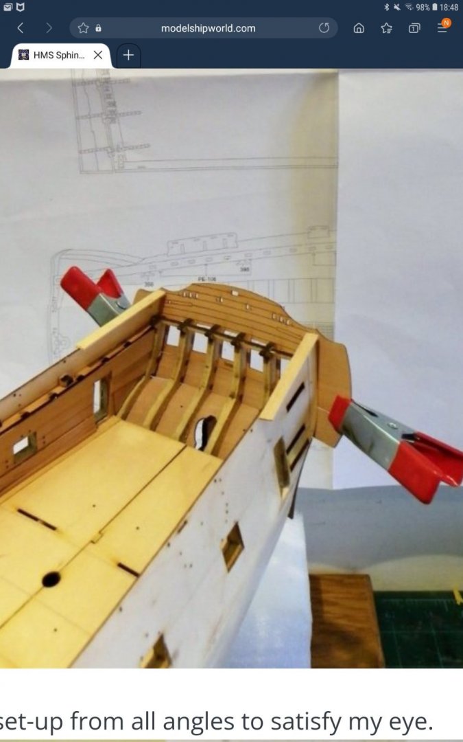
This is how to set them
-
Ron It looks like your stern fascia is set low to me.
-
The key is to get the stern fascia correctly positioned and then the two counter patterns can be positioned.
-
Yes it is far too low. Please take a look at BE's build log also which shows perfectly how the fascia and two counter patterns should be positioned.
-
No you would only copper from waterline toward keel
-
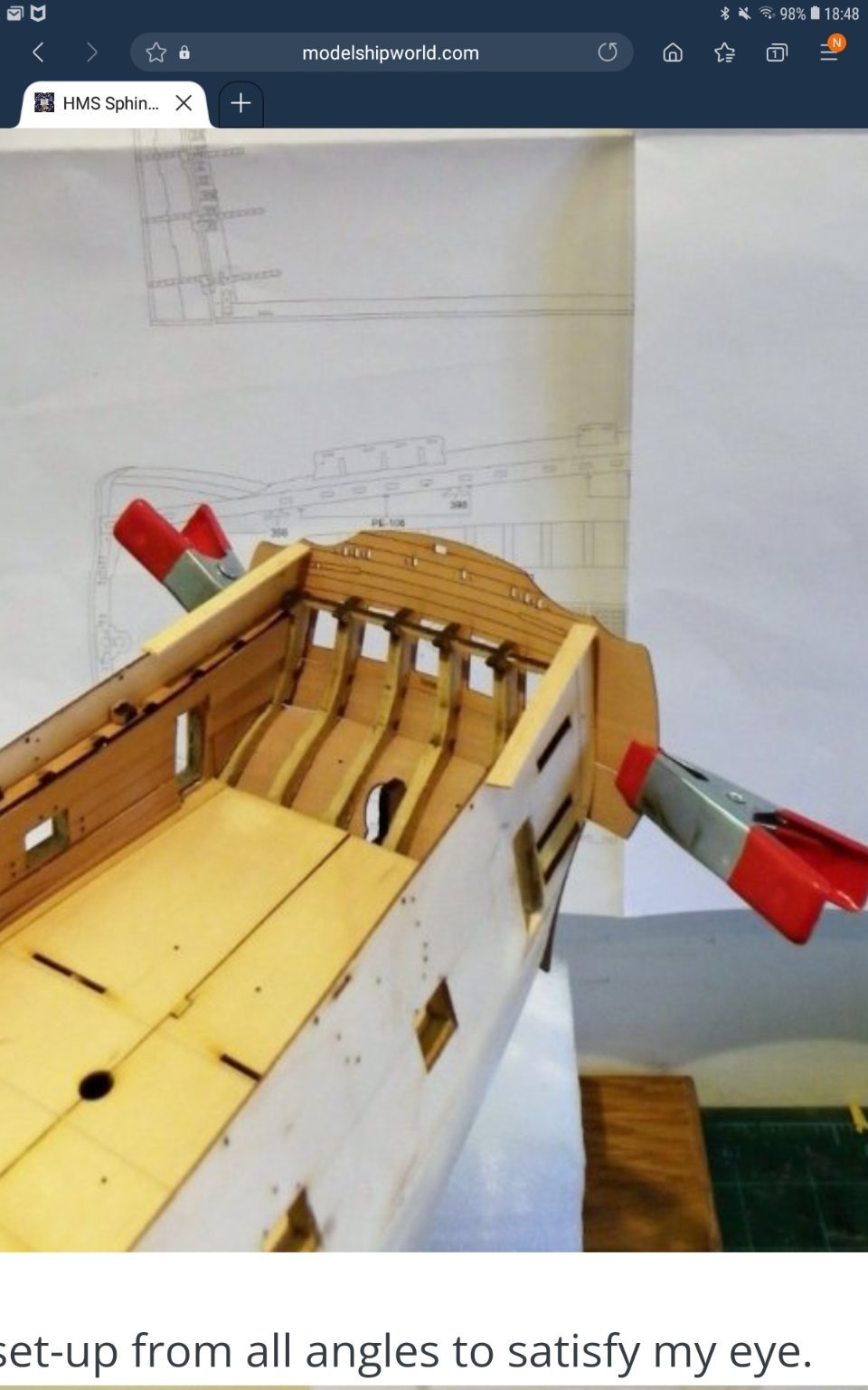
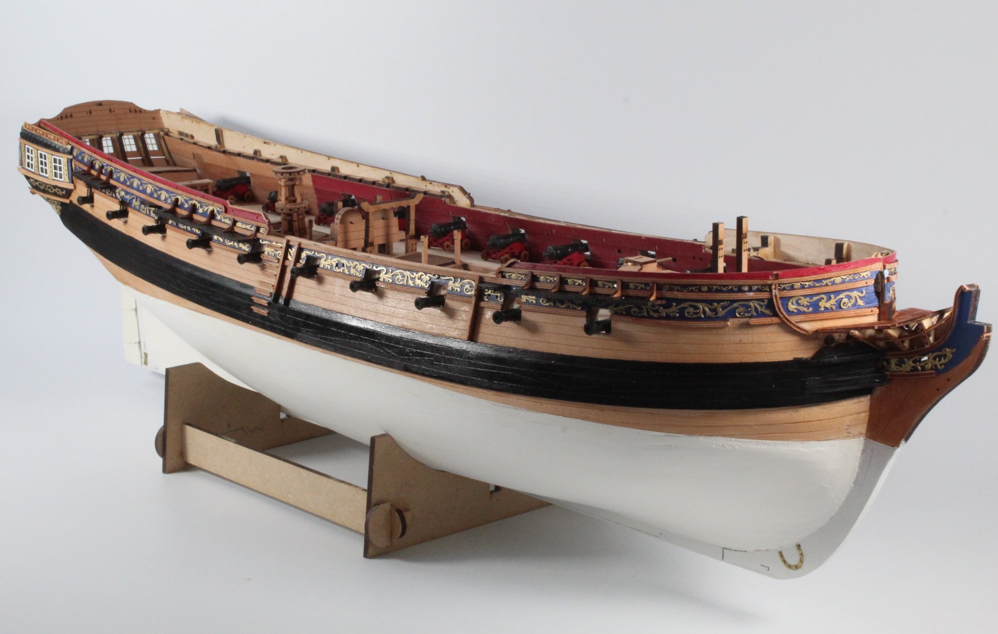
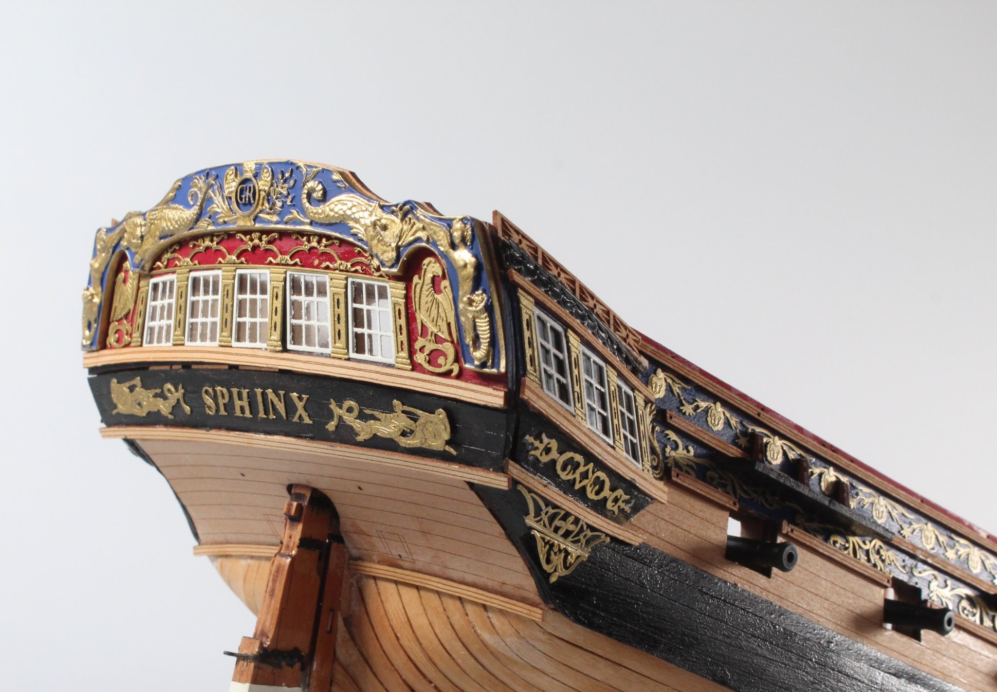
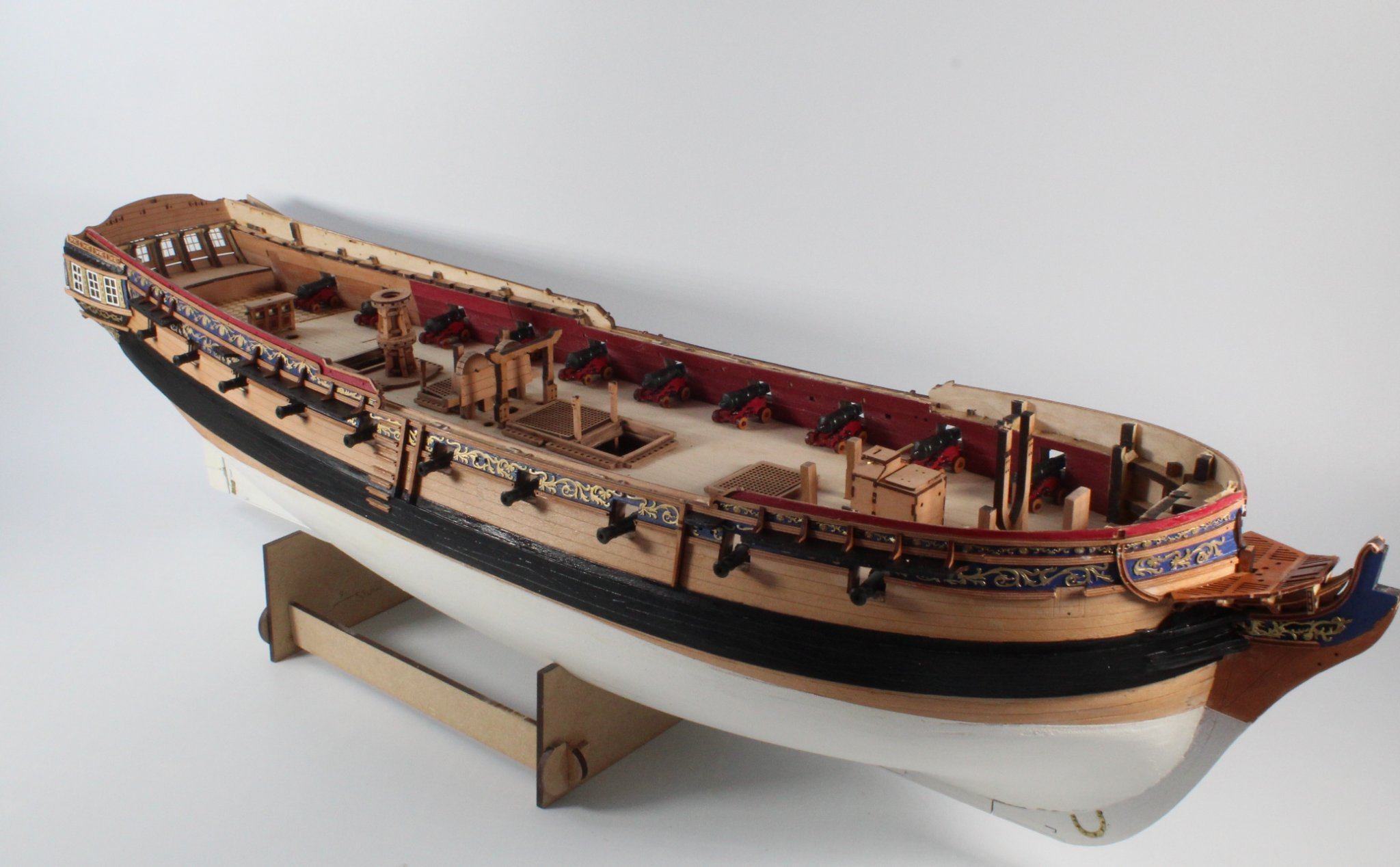
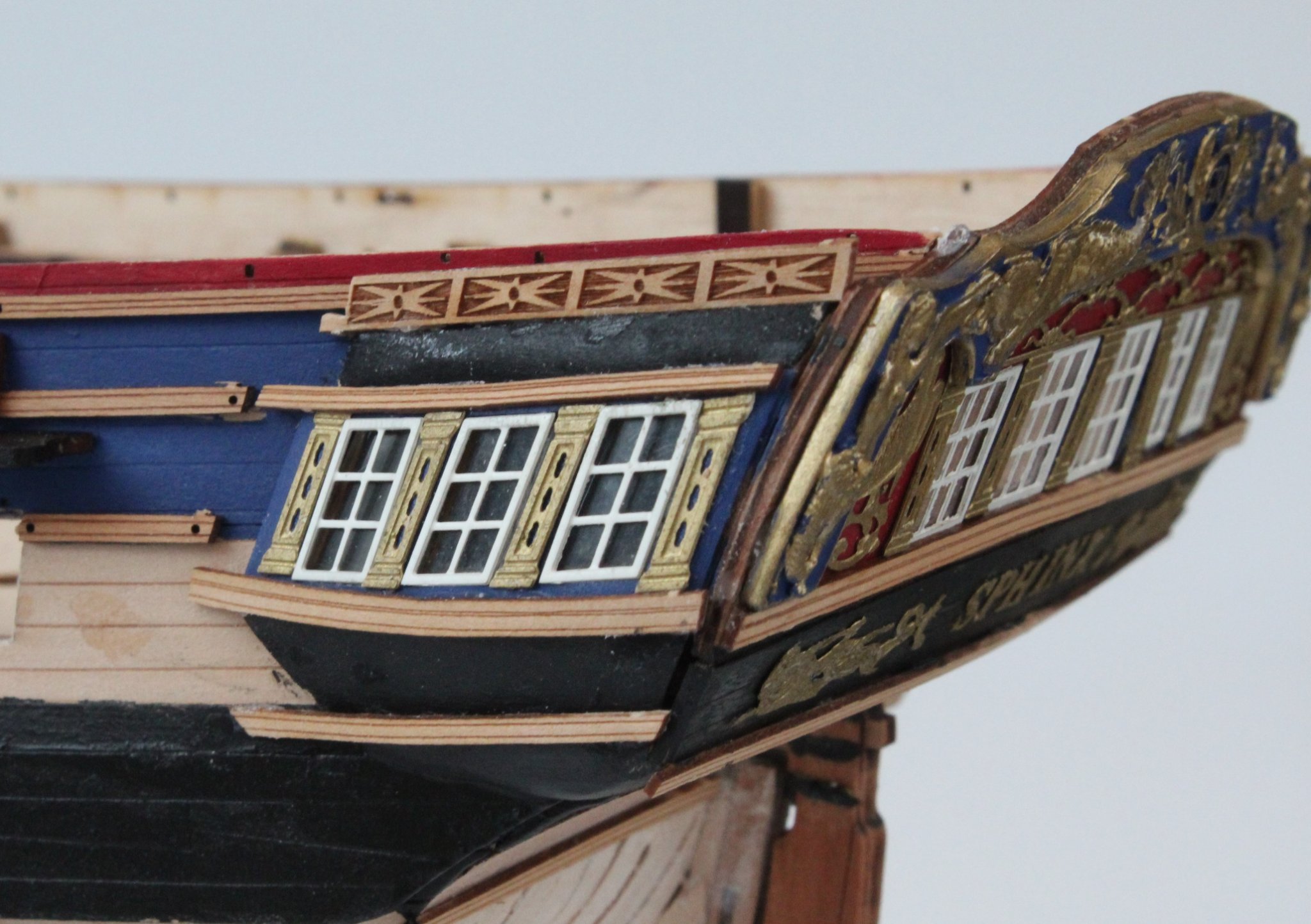
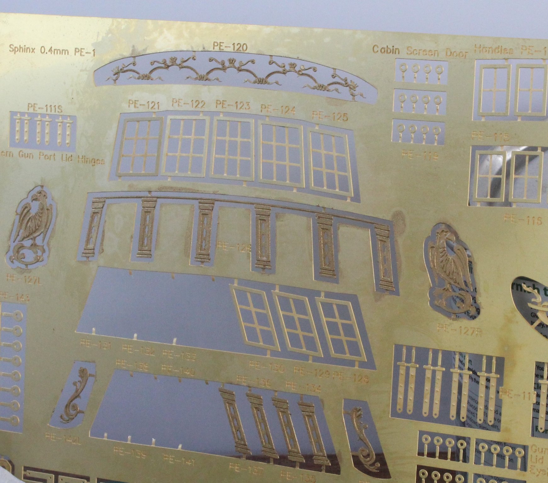
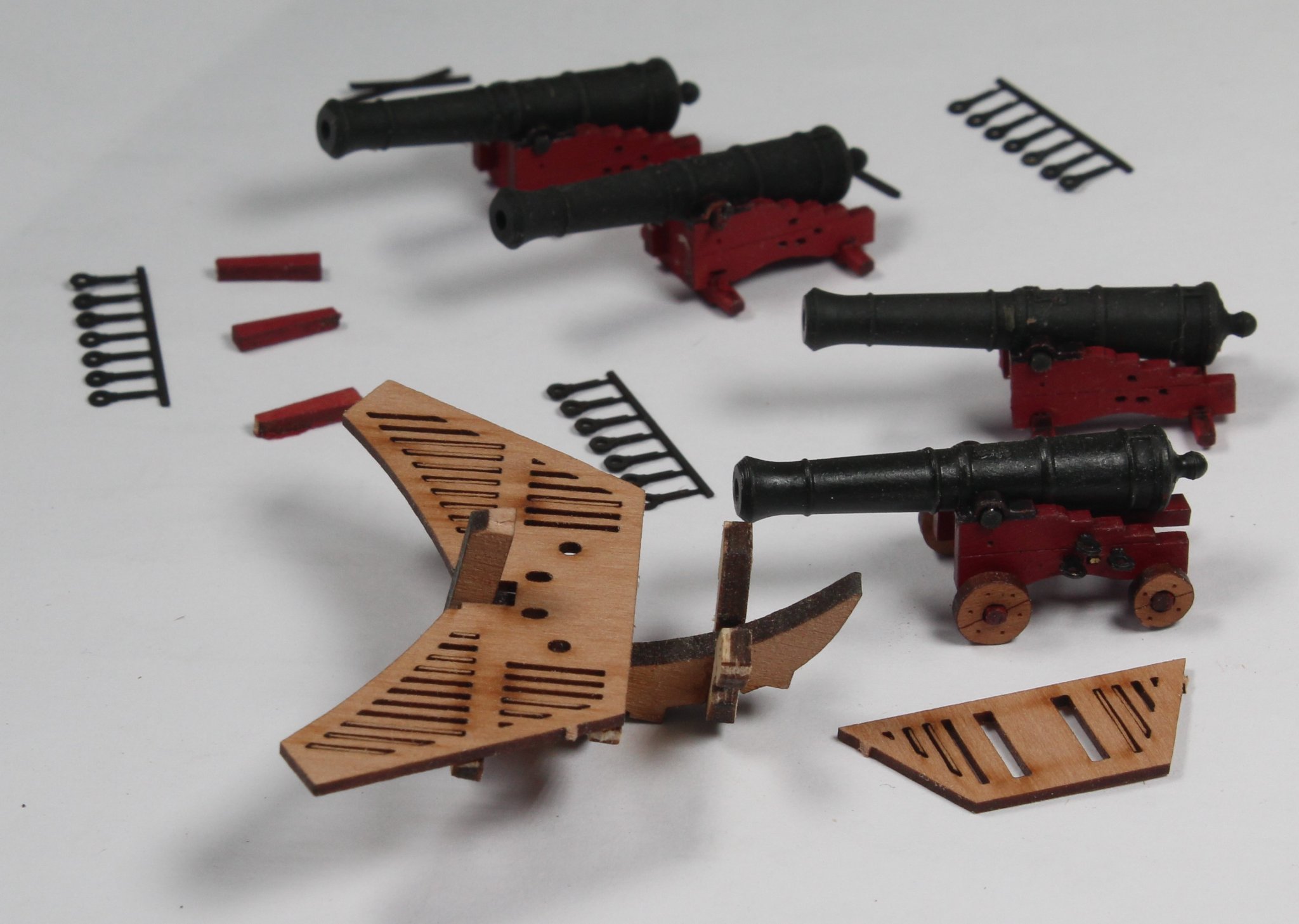
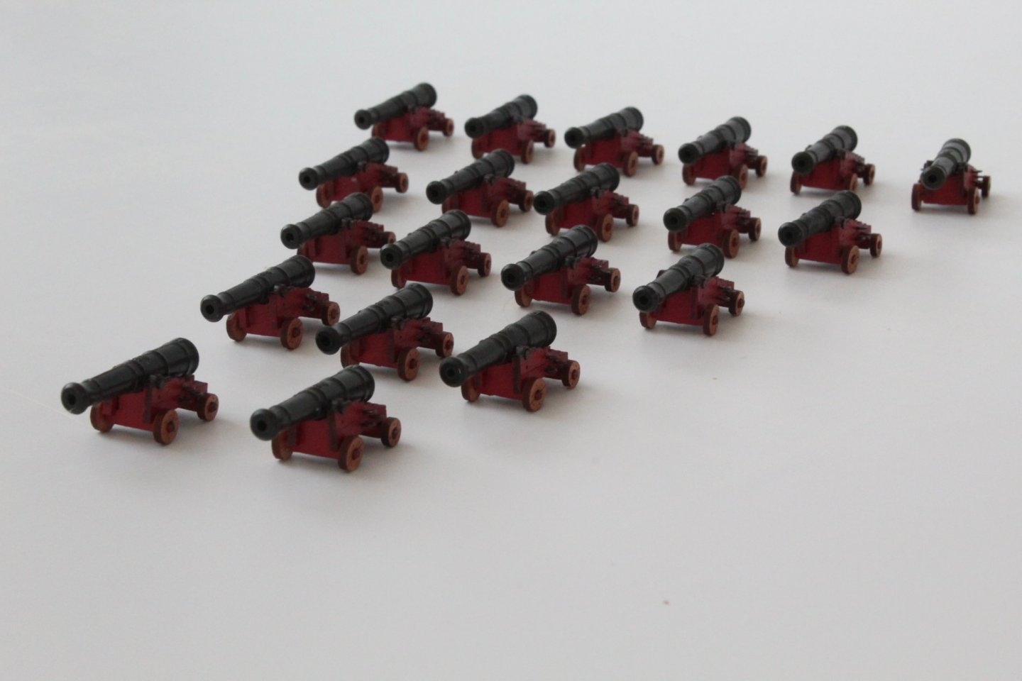
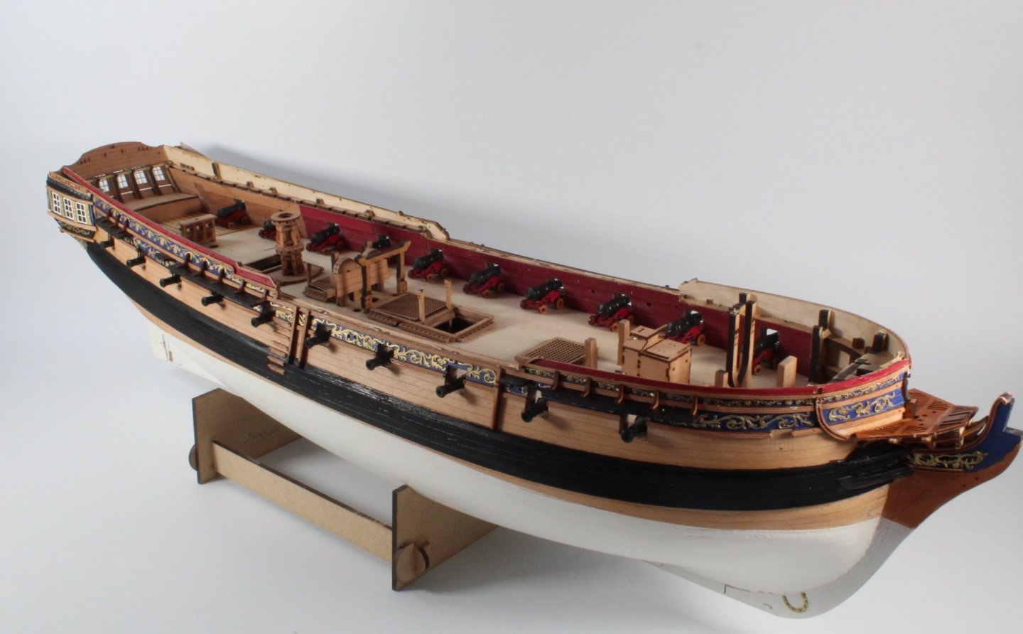
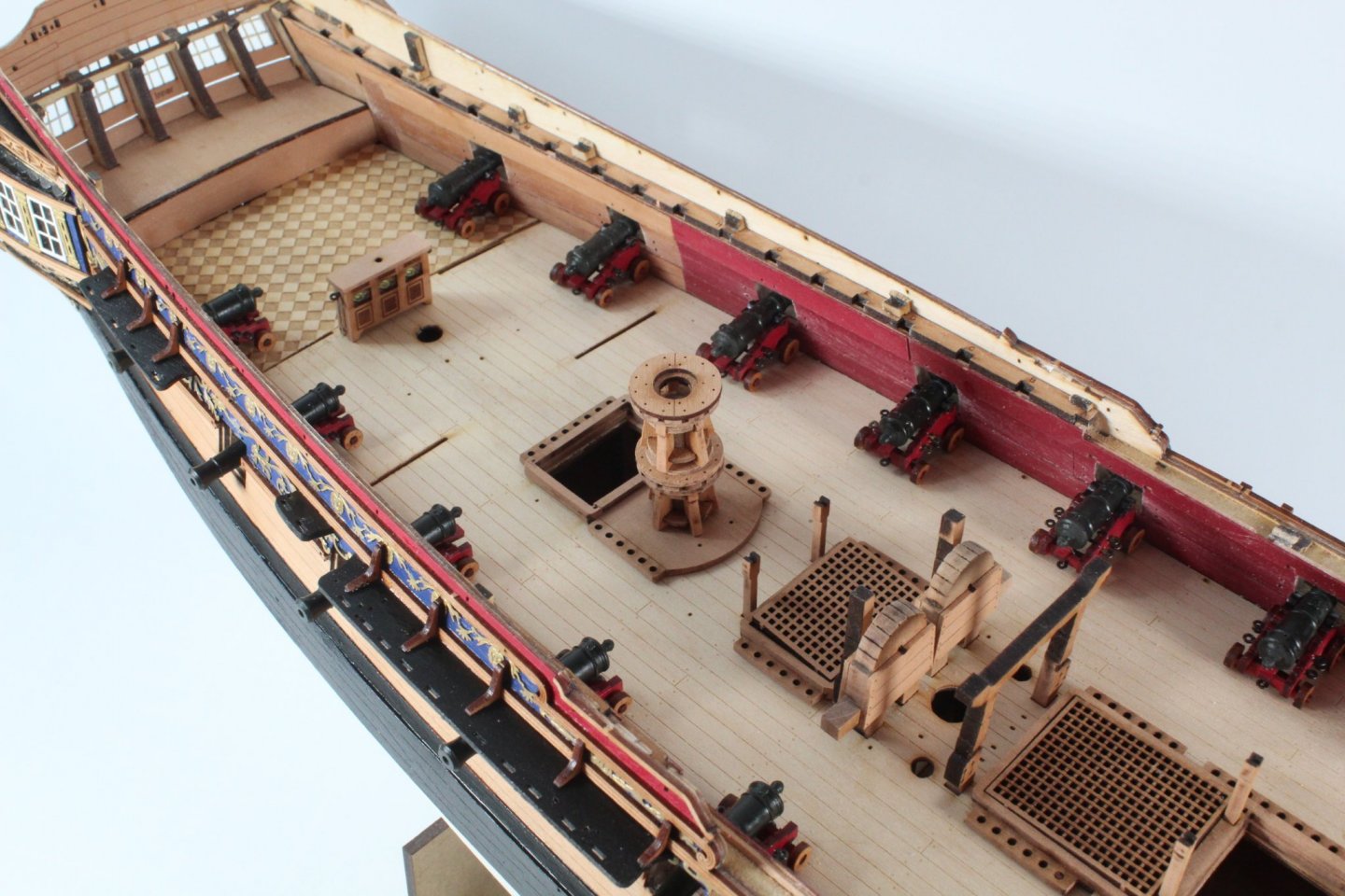
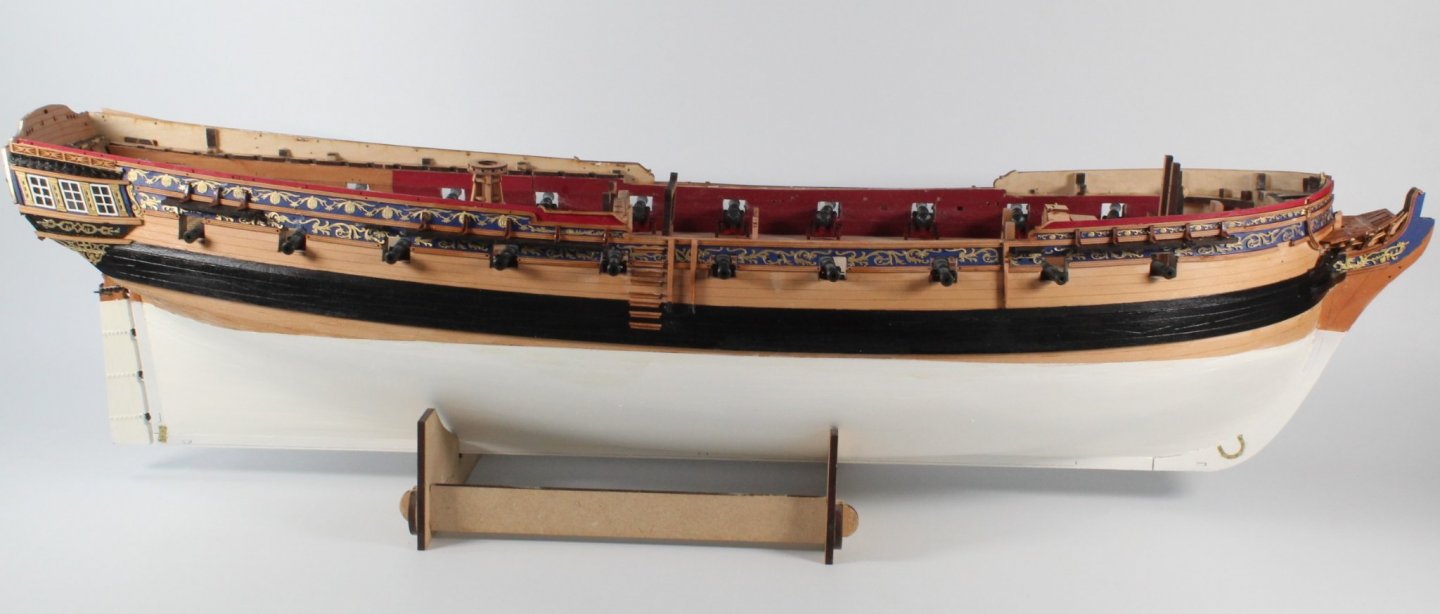
HULL WORK HULL DECORATIONS BUILD MANUAL STEPS 319 - 322 LINK TO MY BUILD LOG INDEX Tools Used Craft knife Klear polish CA Gel Titebond Assembly Process I have completed the assembly of all 20 cannons. It has been a nice little side project with no problems completing this task I have also assembled and fitted the side steps, 8 steps per side required. It was a bit fiddly assembling the side steps, but once I found the right method it was a not too bad. Some steps will require painting, top one blue and lower three black. I have also added all the hull decorations. I started this task but brushing a acetone solution over the PE sheet followed by a soapy water clean. Next I sprayed the sheet with a white primer. The hull decorations were then painted gold. Using the plan sheet as a guide the various friezes were added. I started with the Klear polish method but found it better to also apply a touch of ca gel to the ends of each frieze. When fitting the friezes I noted how important it is to ensure the rails have been correctly positioned. I ended up having to remove and repositioned some of the lower rails. This picture shows the quarter gallery, I'm so glad I have another kit on order so I can make a much better job of it next time around. This picture shows just how bad a job I made of the quarter galleries and stern fascia I had completed many of the deck fitting as side projects so I thought now would be a good time to dry fit them to the deck The binnacle and upper deck capstan are included in this picture My Sphinx build does not look quite so bad when view from distance.🤣


-
Hopefully it can be repaired.
-
Looks like you've done a great job, well done.
-
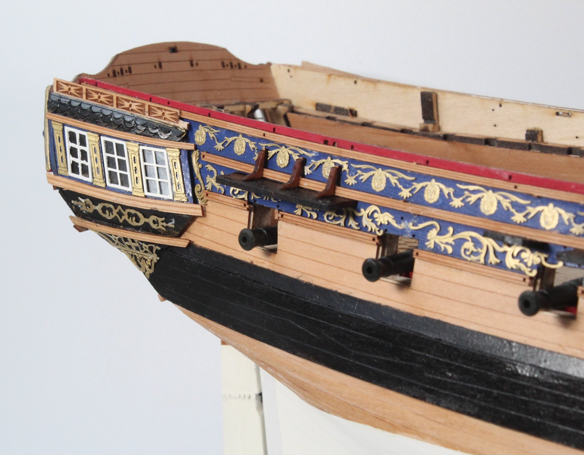
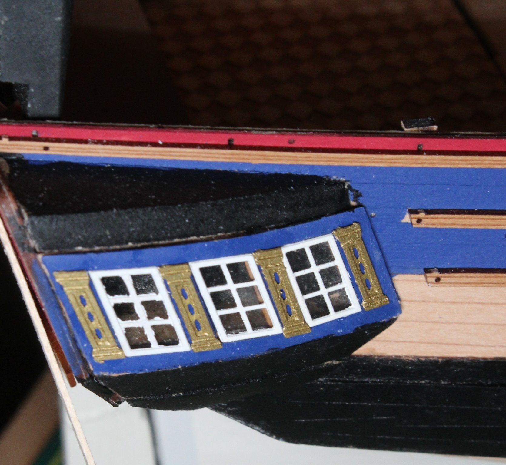
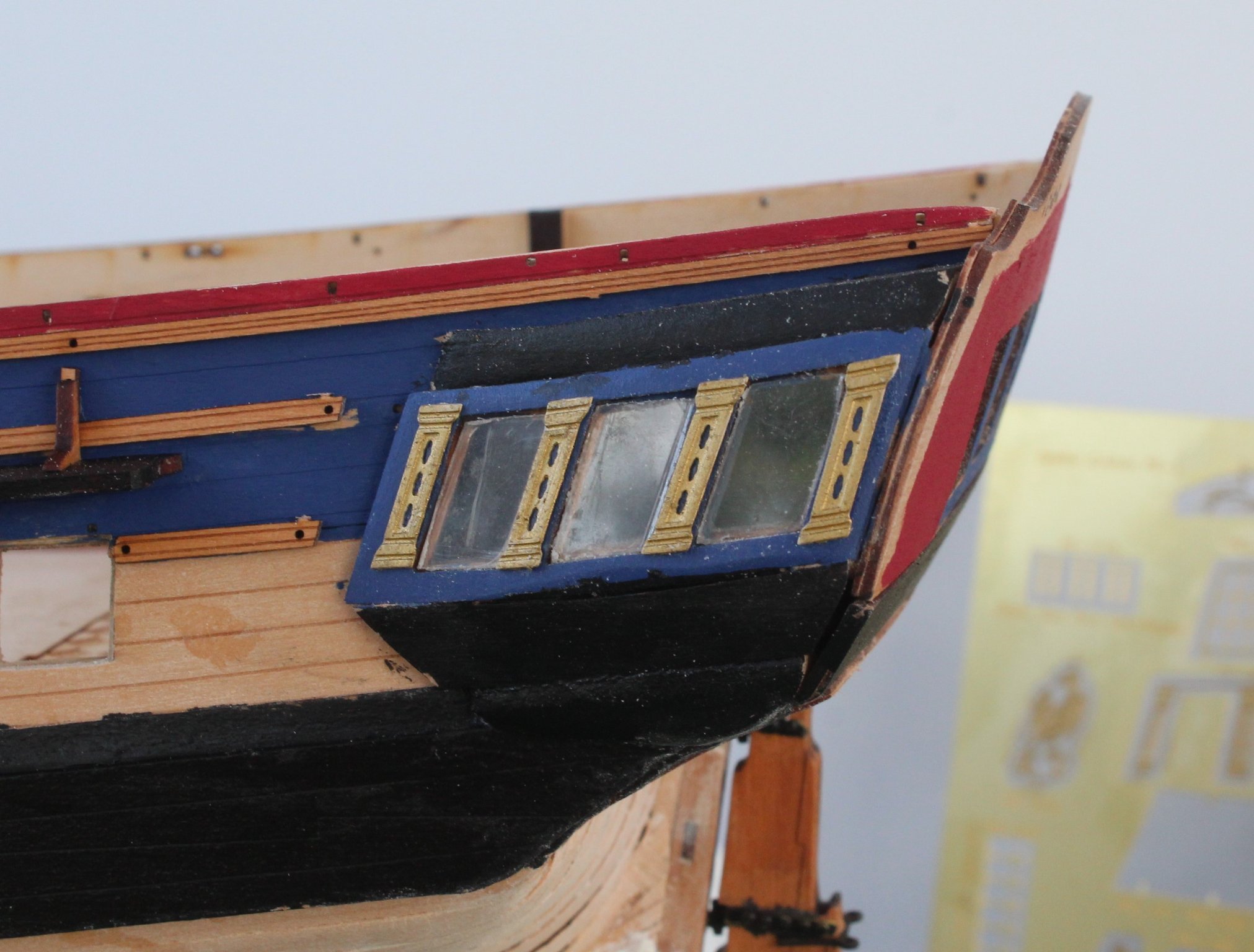
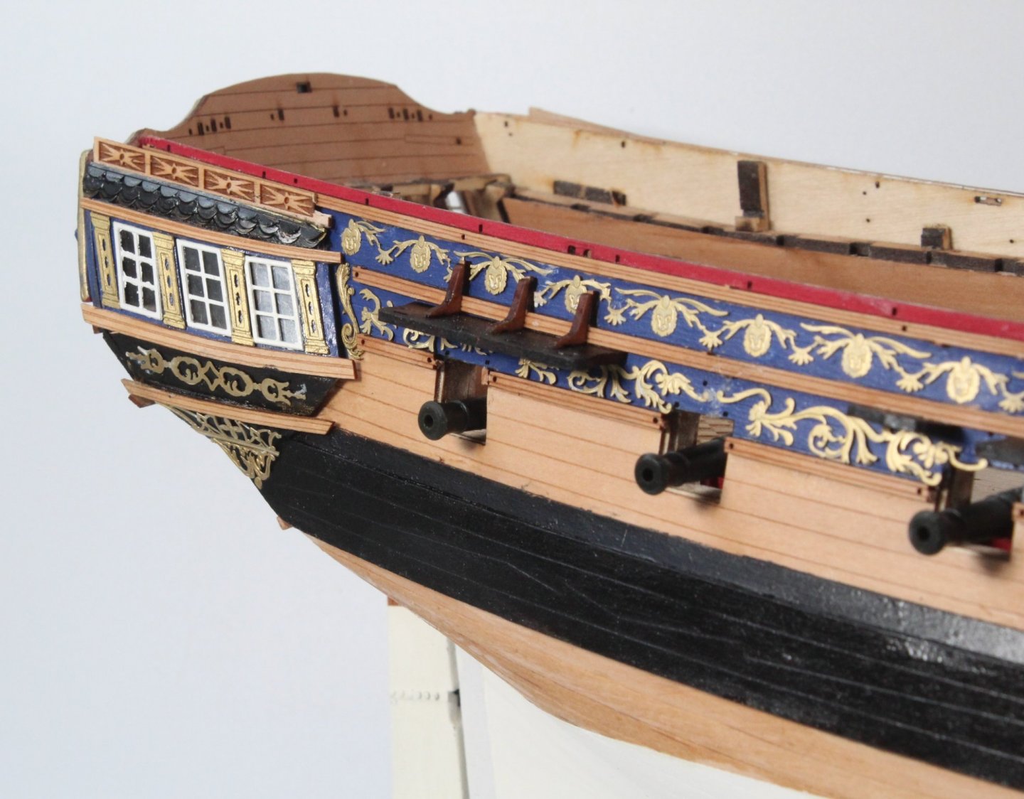
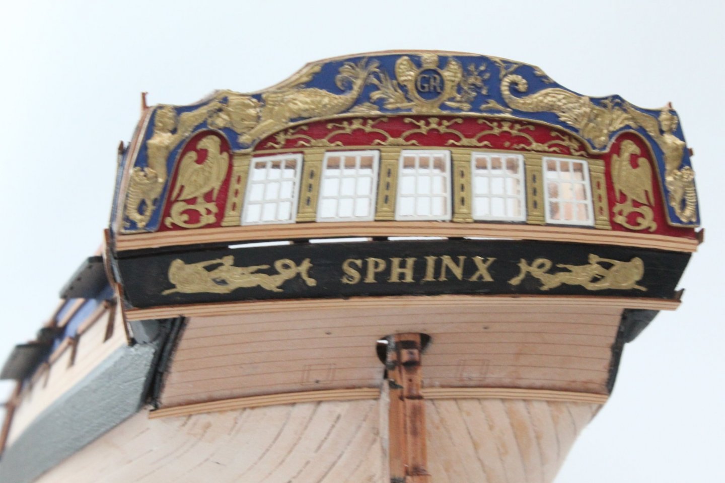
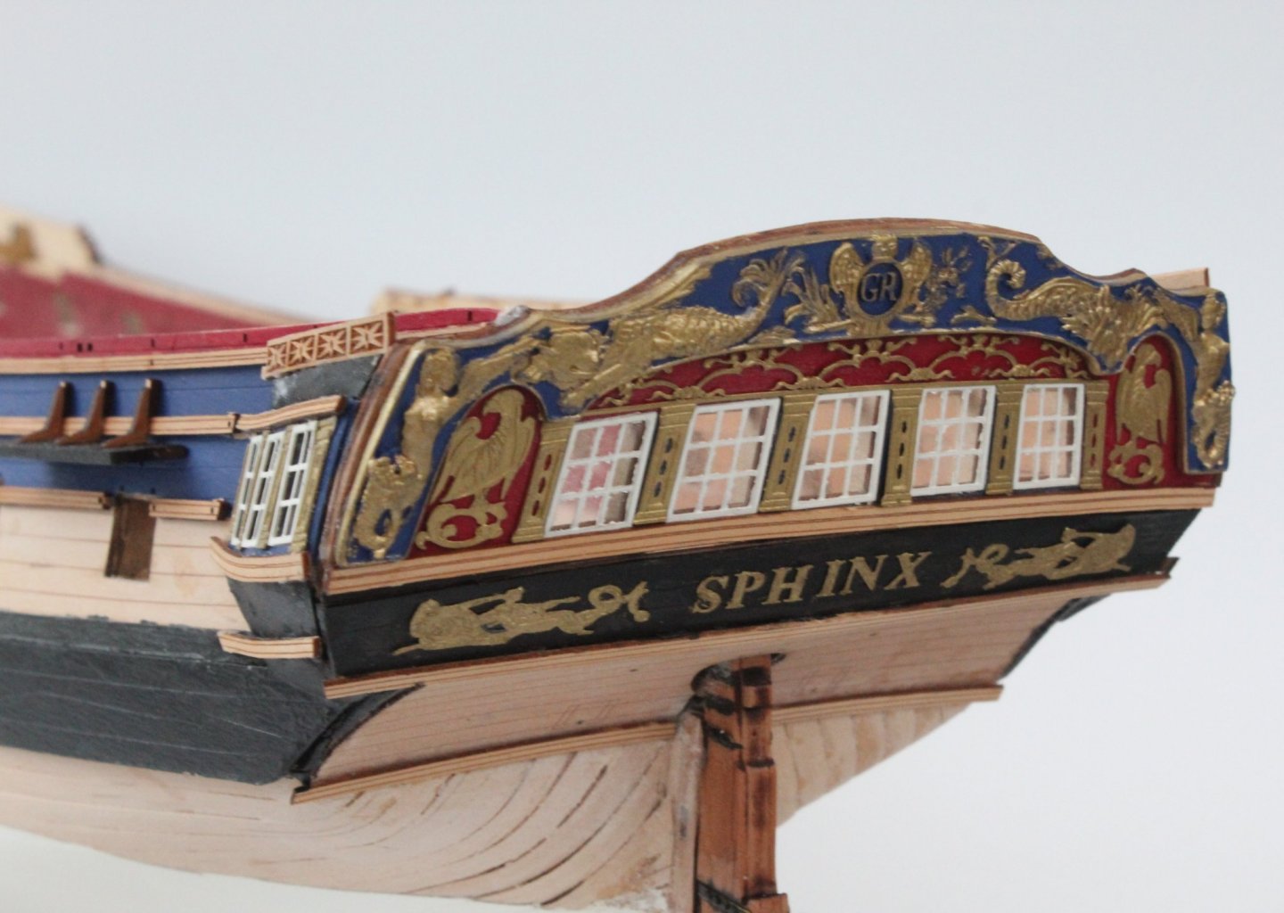
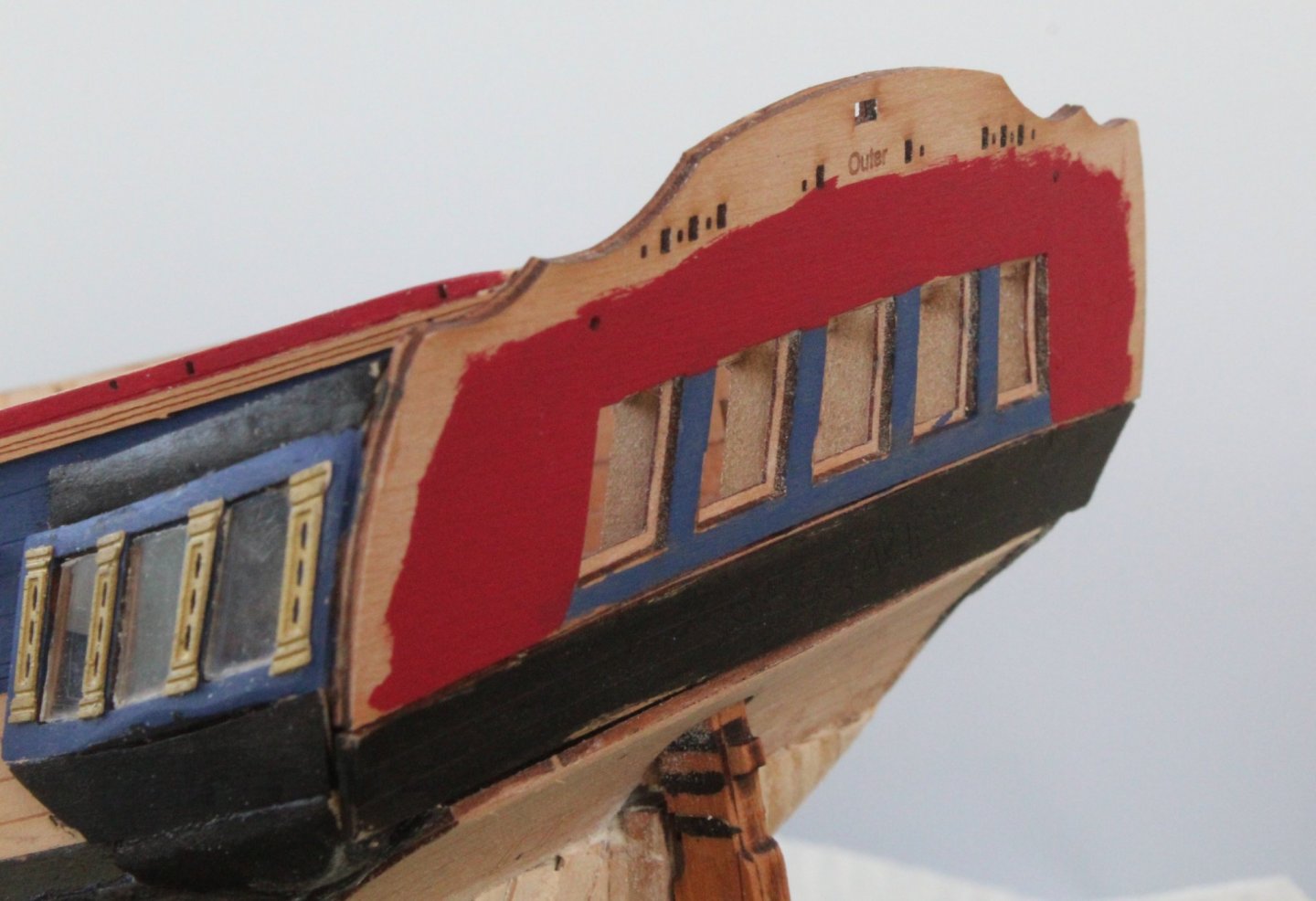
With apologies to @chris watton for how I have managed to turn his beautiful design of the quarter galleries and stern fascia section of the Sphinx in to a right dogs dinner. I would also like to apologise to @James H for not been being able to execute his very informative build manual instructions with the top quality pictures. Also sorry to @glbarlow for not correcting the mistakes in my prototype build. I think the pictures attached to this post make a nice horror show precursor to Halloween. 🤣. When I have received the new Sphinx kit I promise to make a much better job😀 Any news on the expected release date Chris for the next batch? With regards to the stern fascia area I have fitted all the rails, the resin moulding and all the PE parts. With all the parts fitted it really does highlight just how badly misaligned my build is in this area. I cannot stress enough just how important it is to ensure the two counter patterns and stern fascia patterns are correctly positioned as instructed. Take a look at Blue Ensign's build log in this respect which is a great method to follow. When painting the resin casting I used the same gold paint as James, diluted with a couple of drops of isotropic alcohol and a very fine paint brush. As soon as I put the paint on the resin it flowed beautifully over the raised resin sections and was looking very good until I noticed the paint had continued to flow and spread on to the flat blue surface. In future I will let the paint start to set before painting so it not quite so runny when it being applied. Here is a couple of pictures of how the stern fascia looks on my build. The misaligned parts are very clear to see. It is not a pretty sight and I am deeply embarrassed with how it looks. As can been seen on the next photo the quarter gallery is also a bit of a mess, noting I have not fitted the PE parts yet. As you will no doubt note the quarter gallery rails do not align with the stern fascial rails as they should. Another example of my shoddy workmanship.

-
Great information, looking like an excellent build so far.
- 858 replies
-
- 2
-

-
- Sphinx
- Vanguard Models
- (and 1 more)
-
My aim is to continue to show the errors of my ways with this build so others do not follow in my footsteps, to try out ideas both good and bad and not to worry too much with how this model turns out. I am enjoying the build and fully accepting my build standard it is not a very good example of a brilliant design or what the kit deserves. I have learnt so much with the mistakes made and once the next batch is released I can take my time to build a much better model.
-
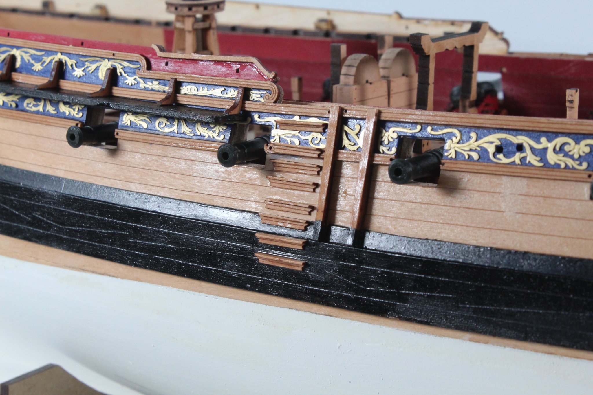
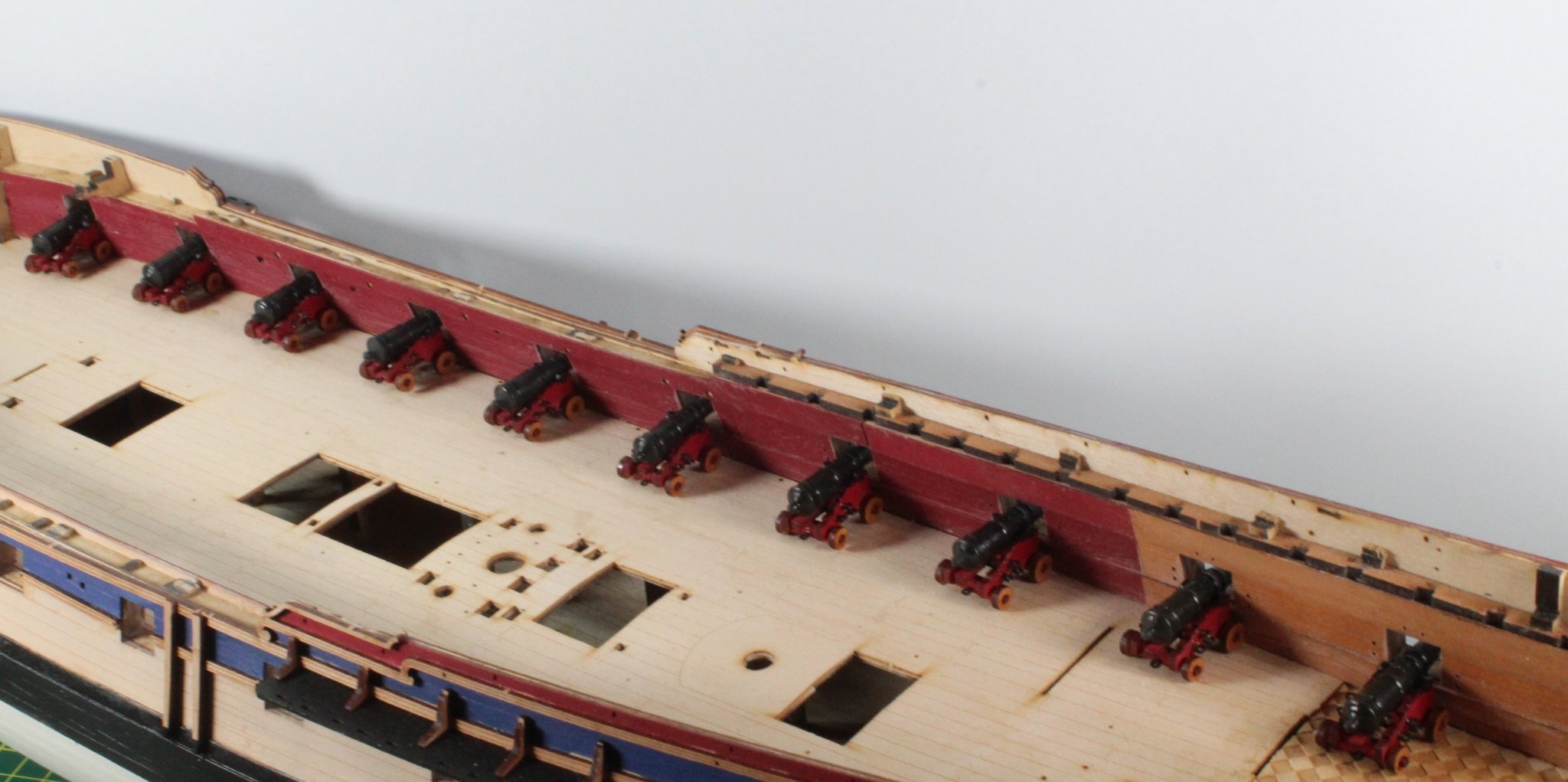
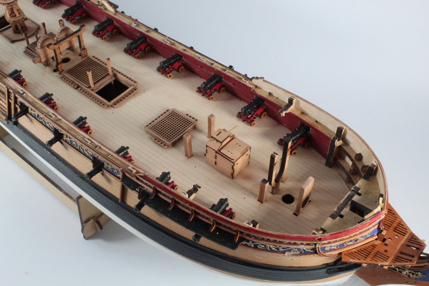
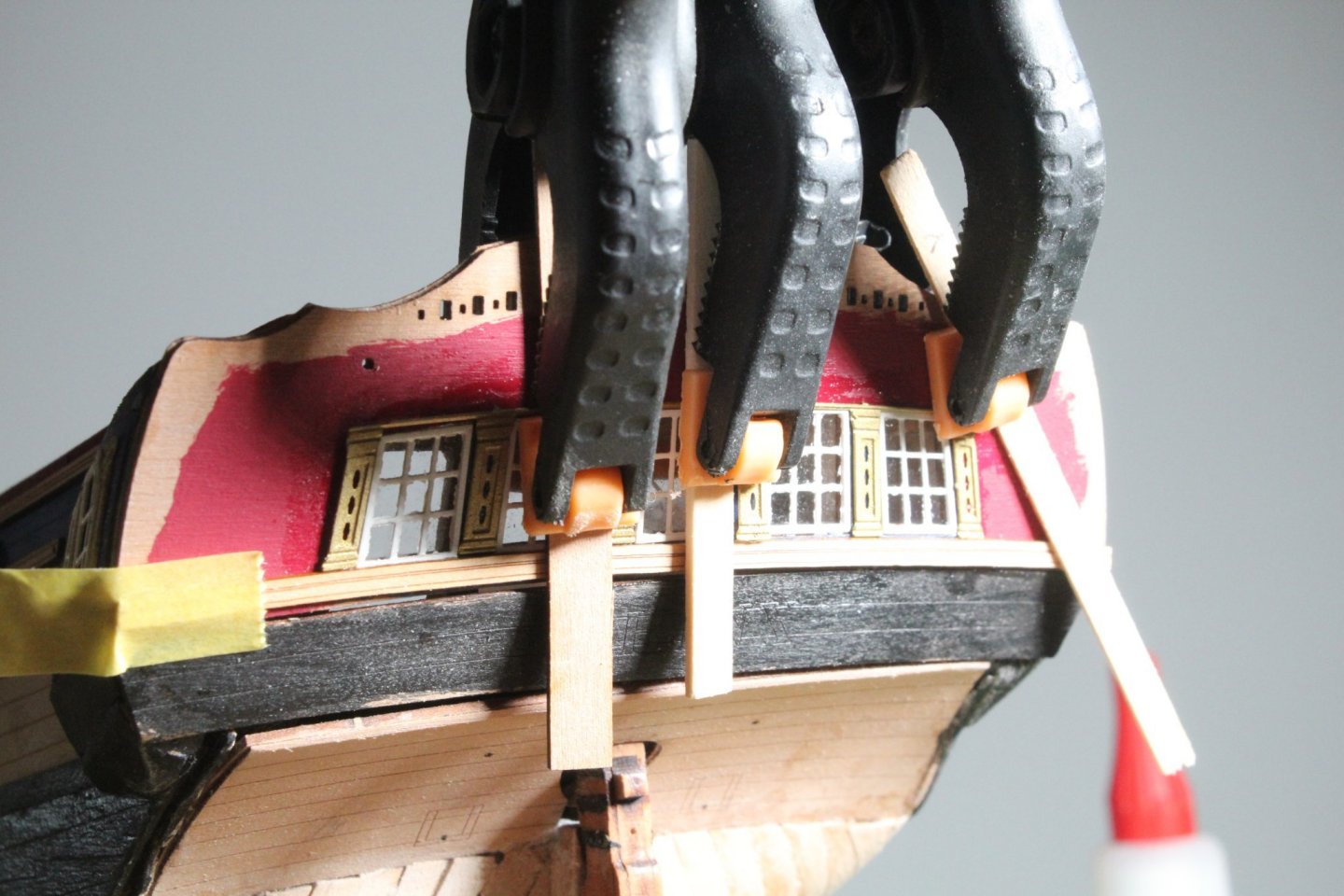
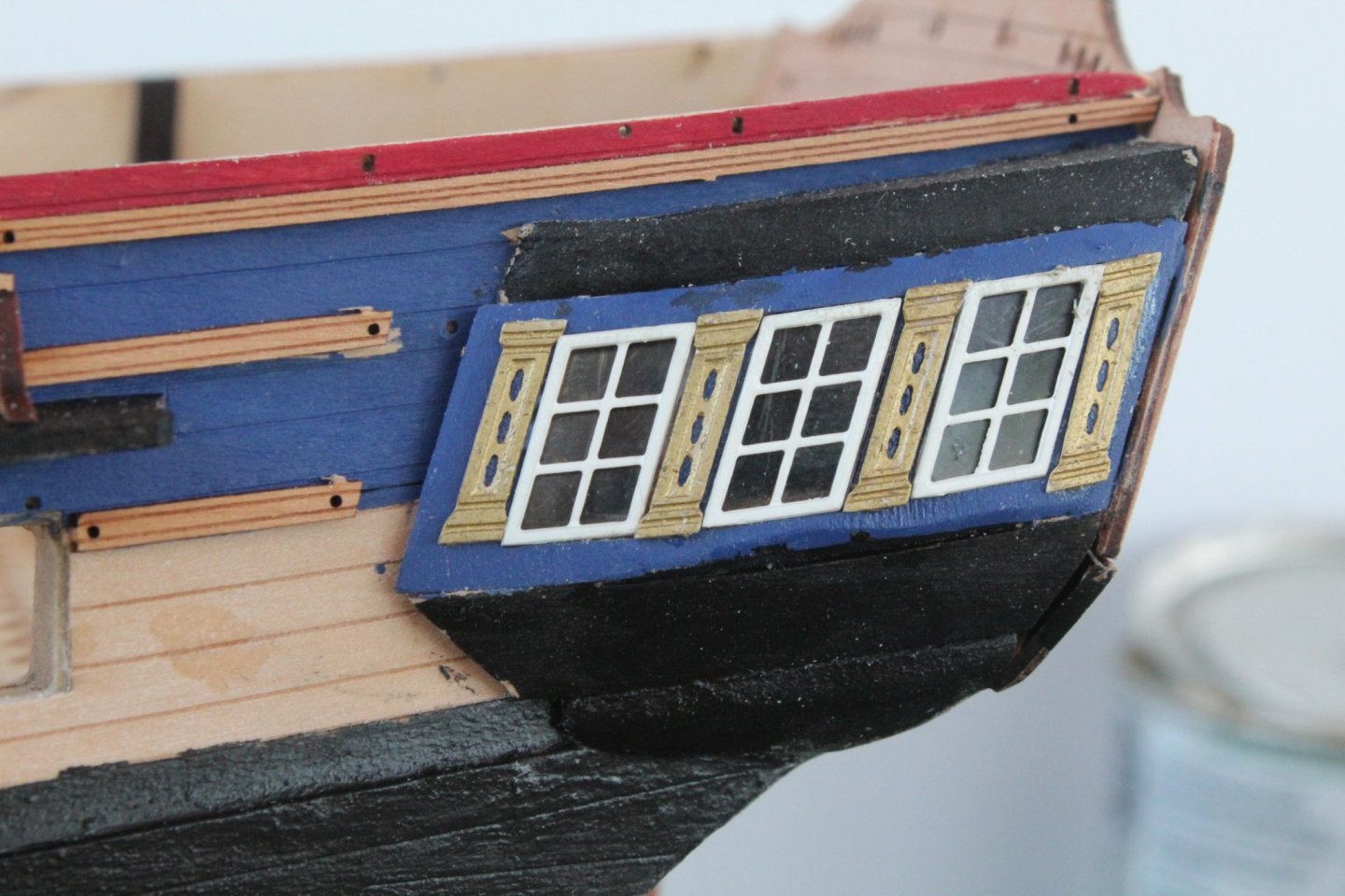
All windows, frames and vertical columns have now been fitted to the quarter galleries and stern fascia. I have also fitted the first stern fascia rail. I used acrylic varnish to secure the clear window panes and the white window frame to the hull assembly. I then used super phatic glue for the vertical columns and rail. I used a few clamps and tape to hold the rail in place as the glue cured due to the slight curve of the stern fascia. The stern fascia vertical column assembly did not require any clamps as the super phatic glue grabbed and held the part in place afterjust a few seconds. This is a picture of the right-hand quarter gallery. I added the vertical columns after the window frames, as per the build instructions which was much better than the method I used on the left hand side where I fitted the vertical columns before the window frames. The excess whie paint on the left hand window frame will be cleaned up. This is a picture of the current state of play with the stern fascia, with clamps and tape holding the first rail in place. There will be a bit of work touching up the paint and using filler to compensate for the misalignment issued reported some time ago on the stern counter patterns. The first 10 cannons have been built so I thought I would take a picture with them positioned on the deck, and the all seem to sit perfectly in their respective gun ports. The remaining parts for the other 10 cannons have all been painted so when I have a spare couple of hours they will be built. Work will continue over the next few days with adding more detail to the quarter galleries and stern fascia.


-
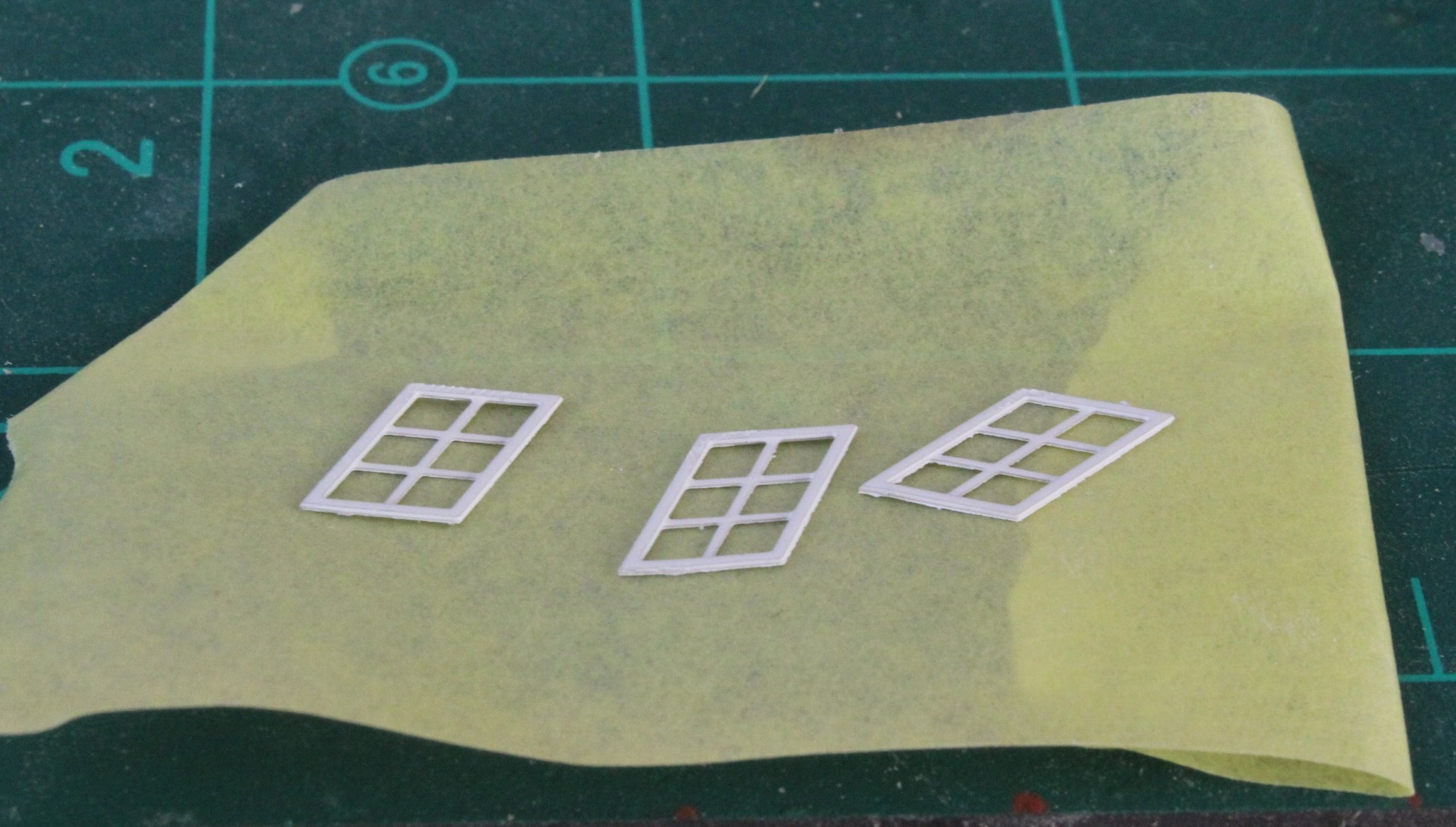
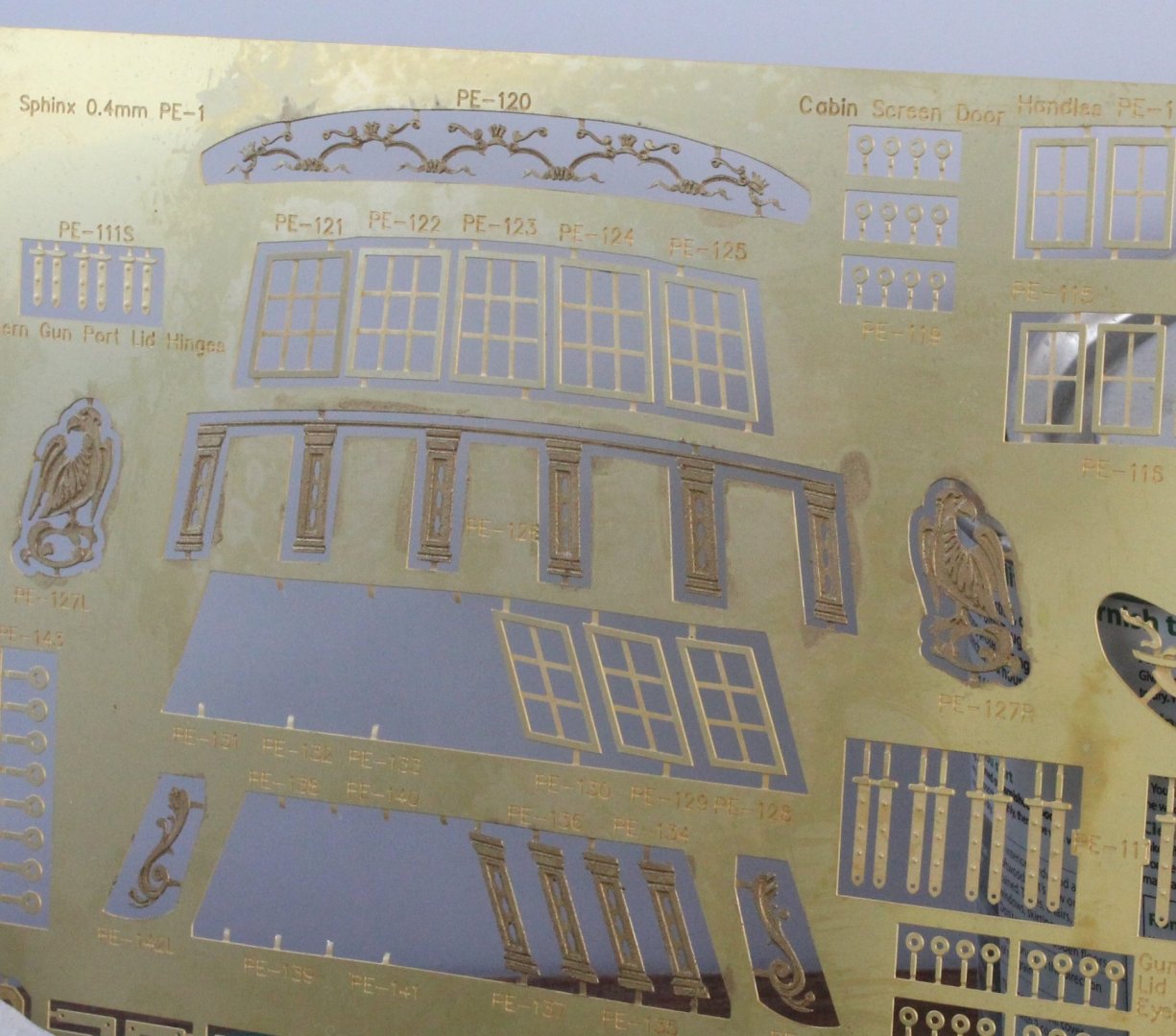
I have started work on adding the windows to the quarter galleries and stern fascia. This will take me a few days to complete the build steps 301 to 319 so I thought I would provide a brief description of the start, working on left-hand quarter gallery. The 3 off laser cut clear windows did need filing before they would fit. Once I was happy with the fit I used acrylic varnish to secure the window panes in the frames. The vertical columns were cleaned in acetone and soapy water and then painted gold. I used super phatic glue to secure them to the quarter gallery. I decided to add these before the white window frames as I was waiting for the white paint to dry. This turned out to be a mistake as I ended up with two misaligned vertical columns. The external window frames were primed and then painted white. Once again I used the acrylic varnish to secure the frames to the quarter galleries. As can be seen in the photo below the two vertical columns at either end are both slightly misaligned in both the vertical and horizontal planes. I could reposition them, but as this is now a prototype build I might just leave them as fitted. The stern fascia panel has been painted red and blue are are now ready for the various clear window panes, window frames and decorations to be installed. I have been painting some of the PE parts gold so they are ready to be installed after the window panes have been fitted. The external window frames have not been painted white which will be my next task. As I was waiting between some of paint drying time I have continued to build more cannons, which will make 10 built in total. In the photo below I have taped the side pieces so the cannon caps can be painted black. I'm also using tape to keep the side pieces upright during this painting process.


-
This is approach I said I would take when I start the next Sphinx, thanks for testing it out, looks the way to go in this respect.
- 858 replies
-
- 3
-
-
- Sphinx
- Vanguard Models
- (and 1 more)
-
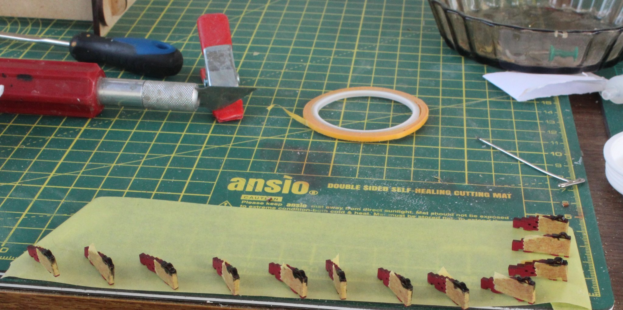
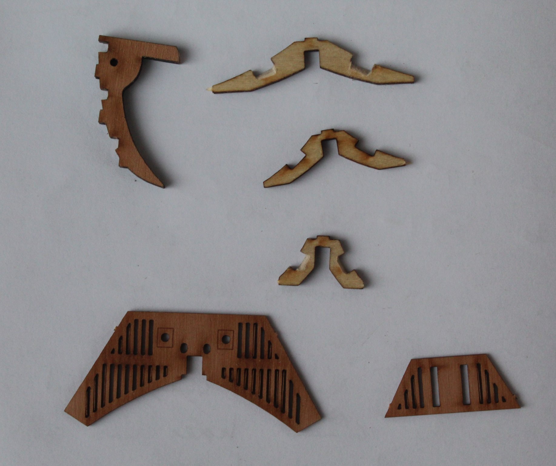
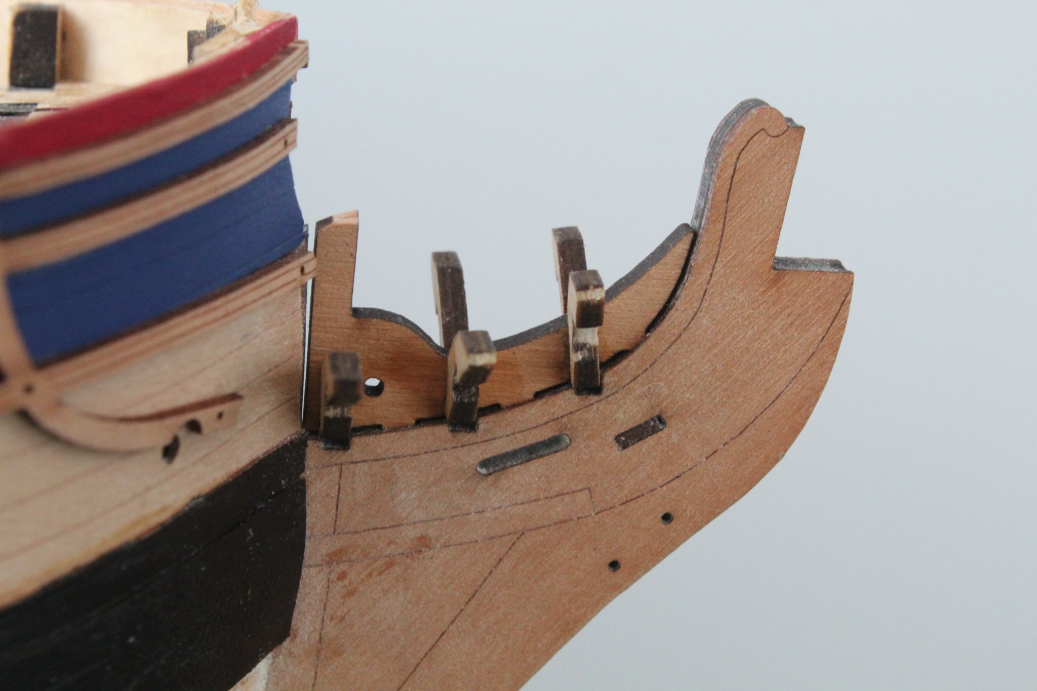
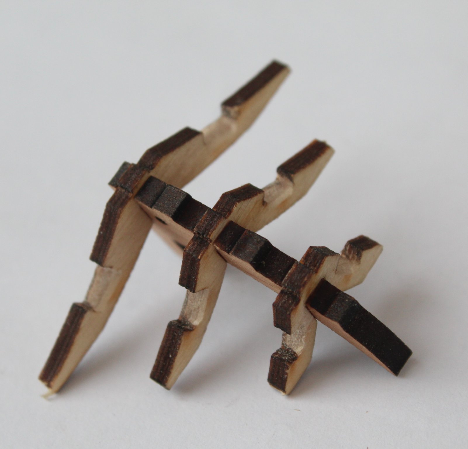
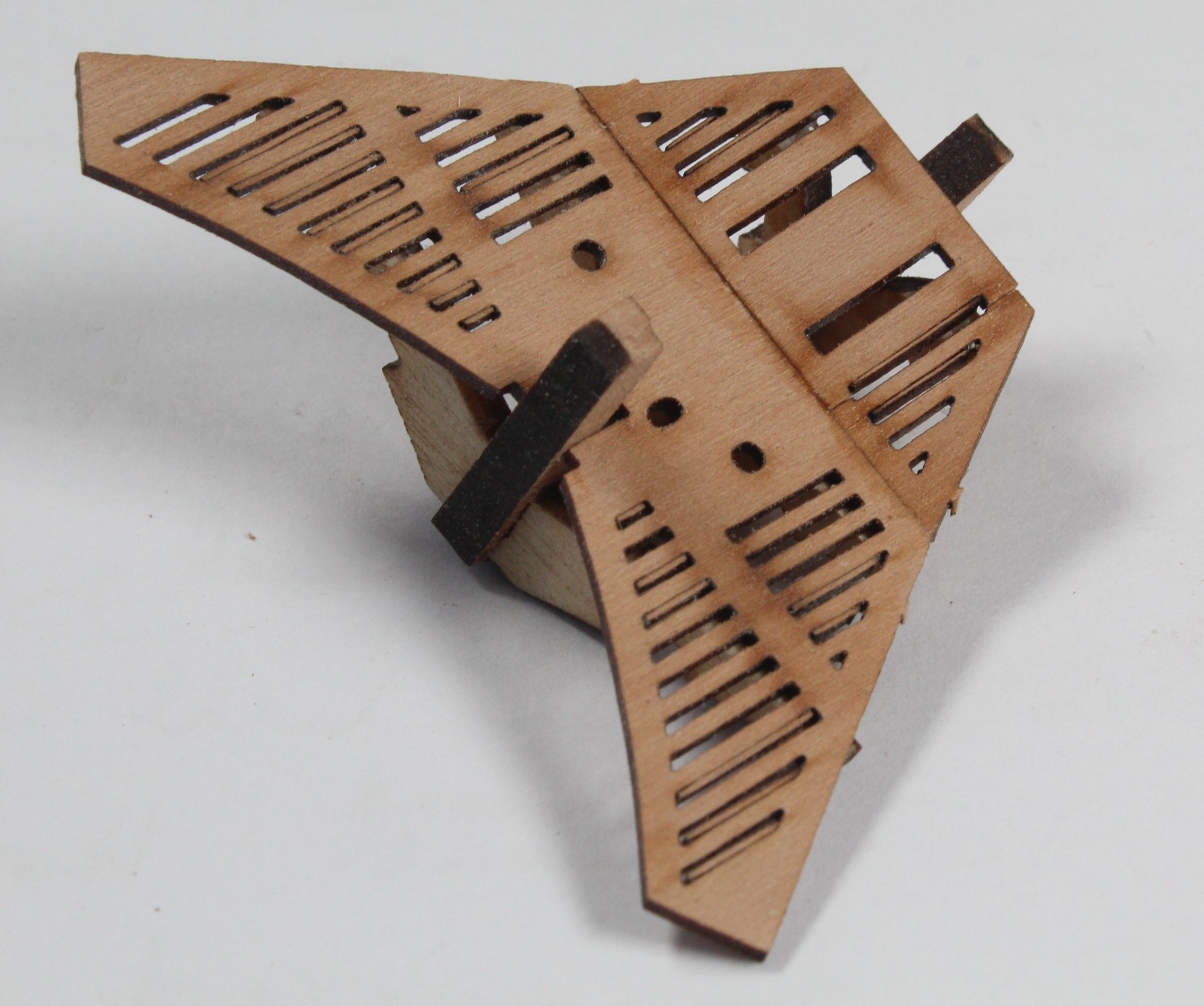
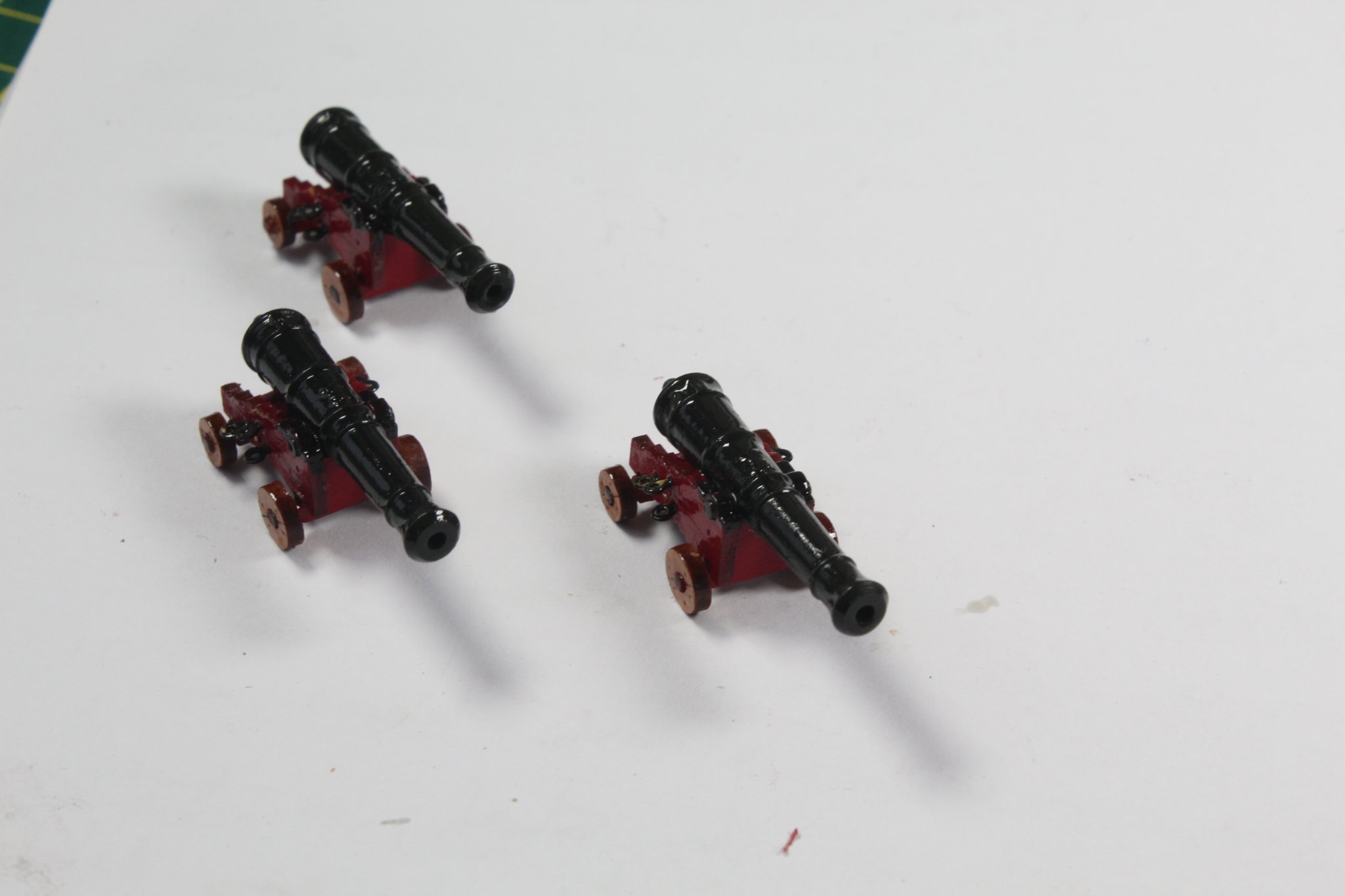
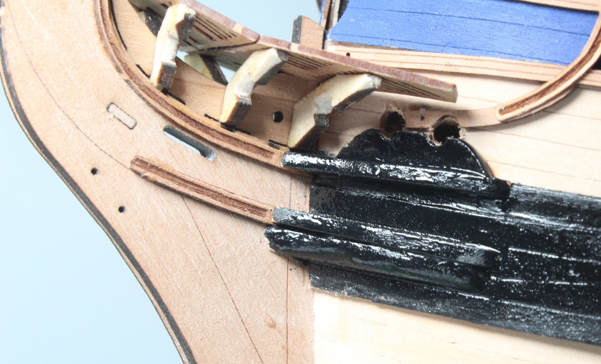
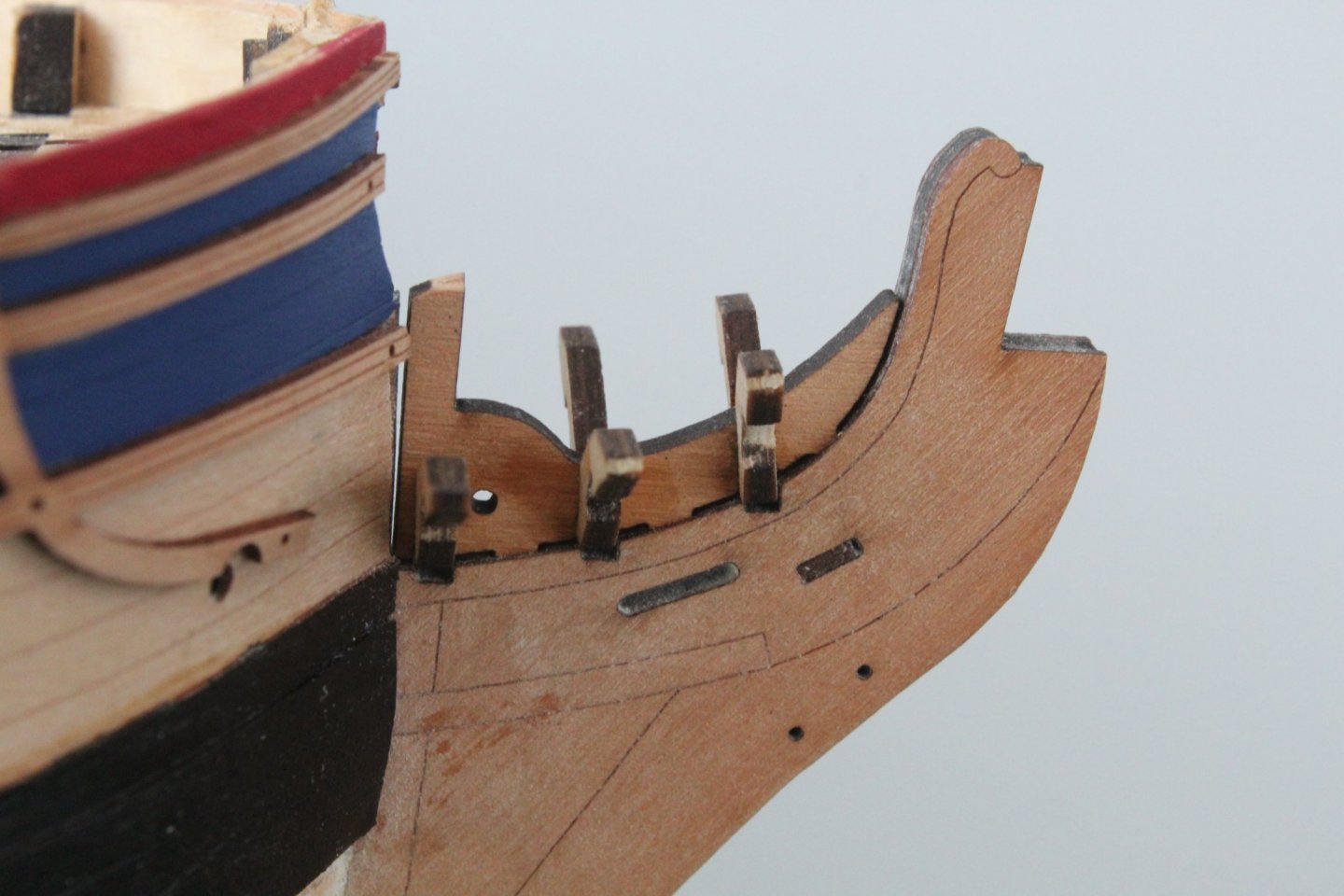
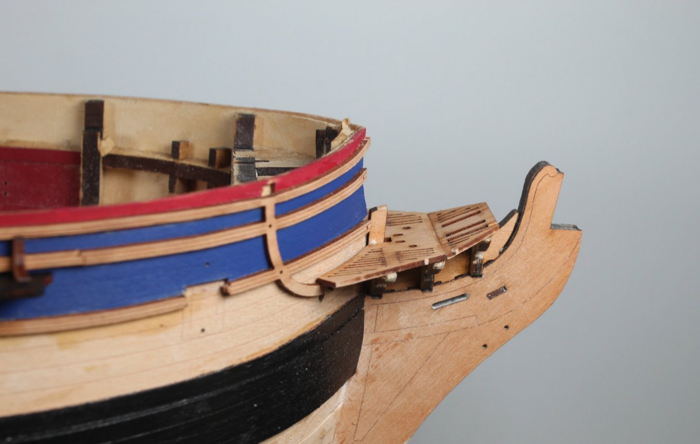
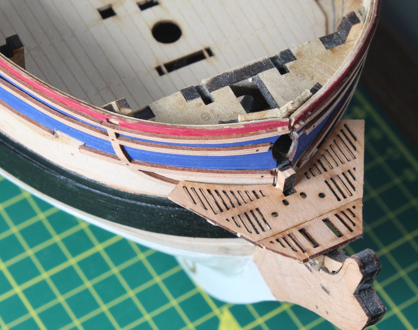
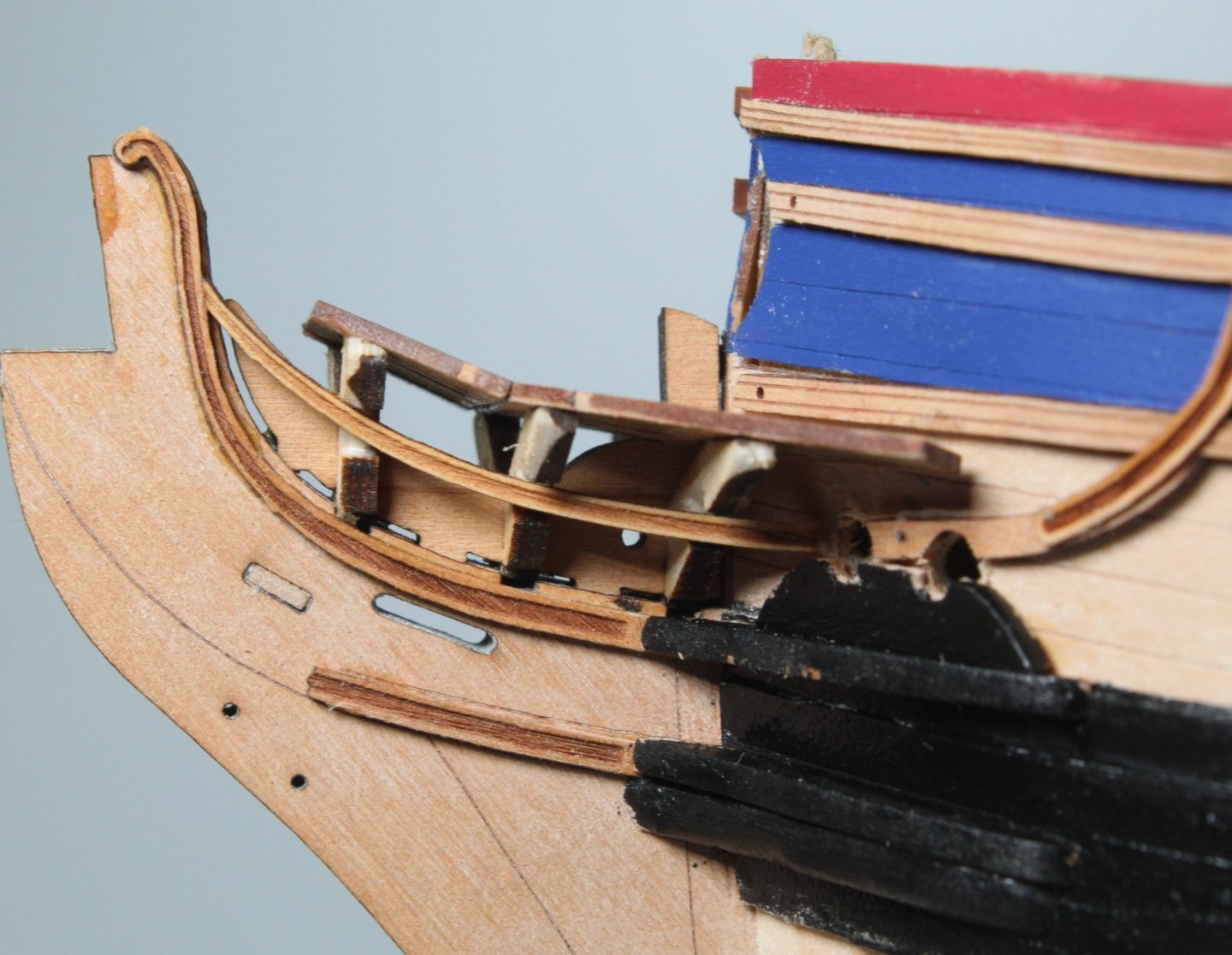
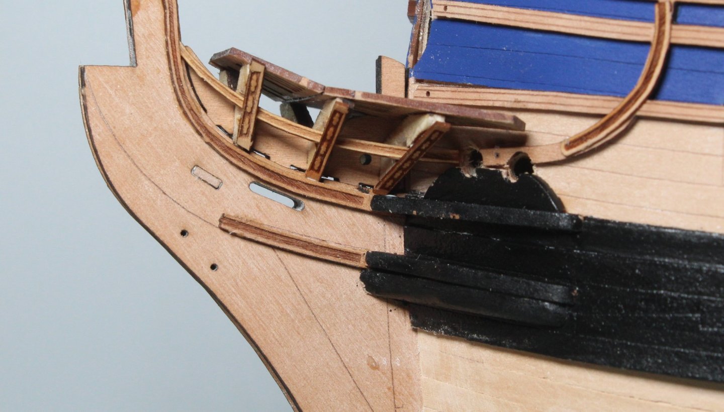
HULL WORK BOW GRATINGS BUILD MANUAL STEPS 276 - 300 LINK TO MY BUILD LOG INDEX Tools Used Craft knife Titebond Sanding sticks and files Clamps Black paint Gathering the materials required 42, 43, 44, 81 (x2), 79, 80, 82 (x2), 83 (x2),160, 161, 171, 172, 173, 174, 291, 292, 384 (x2), 432 (x4), 449, 450 (x2), Assembly Process I am so glad this is a prototype build as I can do this section so much better next time around. The various parts were located on the different sheets and removed. A trial fit of the three off bow v-patterns with the gammoning knee on the stem post seemed to indicate everything was a reasonable fit. Using a file the slots on the v-patterns were bevelled, aiming for a 45 degree angle as per the build manual recommendation. The v-patterns were then glued in place. The contact area of the v-patterns, where the lower bow grating is located, were also slightly bevelled. The assembly was then dry fitted to the stem post so the lower bow grating pattern could be positioned and glued in place. I did use so clamps to hold the grating in place. The assembly was once again removed. To fill in time as the glue cures I started work on building the remaining 19 cannons. As can be seen in the photo below I have started to build 3 cannons, with the first one there for reference. As I was bevelling the joint edge of the upper bow grating the pattern split but thankfully it will not be that noticeable. I also bevelled the contact edge of the v-pattern before the grating was glued in place. The excess v-pattern edges were sanded, and the lower edges were also shaped as per the requirements stated in the build manual. The complete bow grating assembly was then glued in place. The three completed cannons, they are very shiny as then have just been brushed with varnish so are still very wet. Next the bow hair brackets and bow lower rails were glued to the stem post followed by the bow cheeks and hawse bolsters. The cheeks and bolsters required very little bevelling to ensure a good fit the hull. The hawser holes were then enlarged to 4mm, I think this would have been better done earlier on in the build process due to the bow grating. The hawser bolster position was checked. I used a round file to slightly enlarge the parts the sits under the hawser holes. I also sanded the bottom edge. Once I was happy with the fit the part was glued in place. The two wash cants were shaped to produce a nice bevel and glued in place. The hawser area was then painted black, and the paint is still very wet in the photo below Bow lower rails were test fitted. I found it necessary to trim a little bit for a good fit. The bow grating area was completed with the addition of the V-shaped head rail patterns All I need to do now is paint the blue section of the stem post, as indicated in the build manual.


-
It is good to get to this stage and it looks like you have done a really good job. I did sort though the planks and then grouped them in batches based on the thickness, ranging from 0.8 to 1.15mm and I took note of the depth variations along each plank. I still ended up with ridges and dips🤣
- 858 replies
-
- 2
-
-
- Sphinx
- Vanguard Models
- (and 1 more)
-
There are vertical rails between the hortizontal mouldings which provide a full contact area and also lets the builder know where they are to be positioned
-
The knees are glued to the top of the channels and the vertical rails on the hull. I suppose it was done that way to support the channels when the shroud lines are tensioned.
-
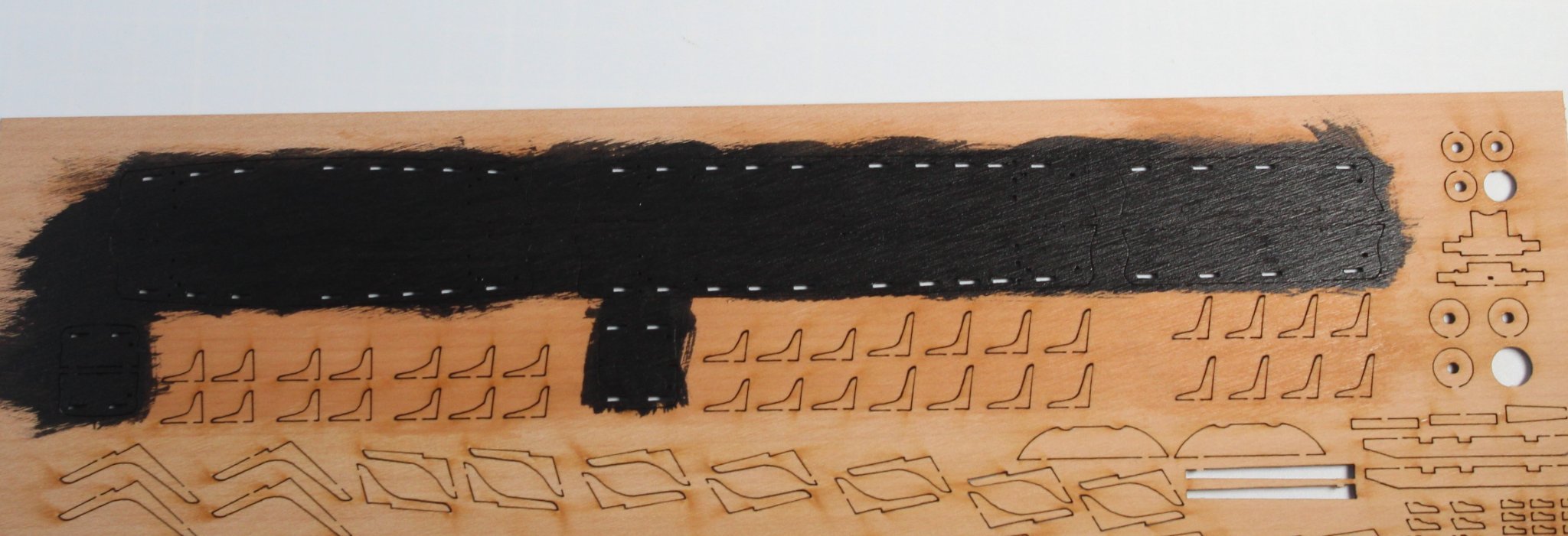
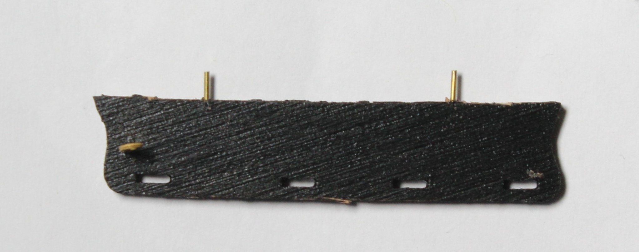
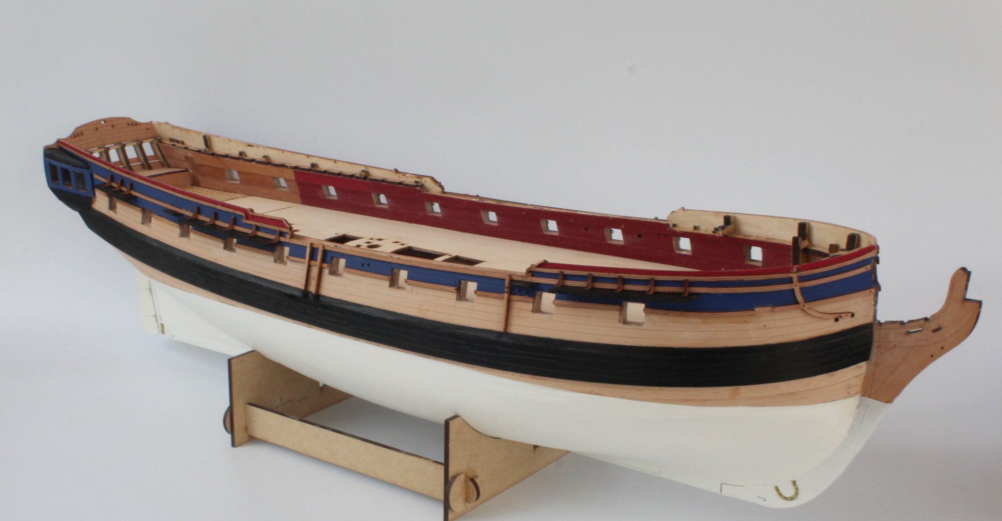
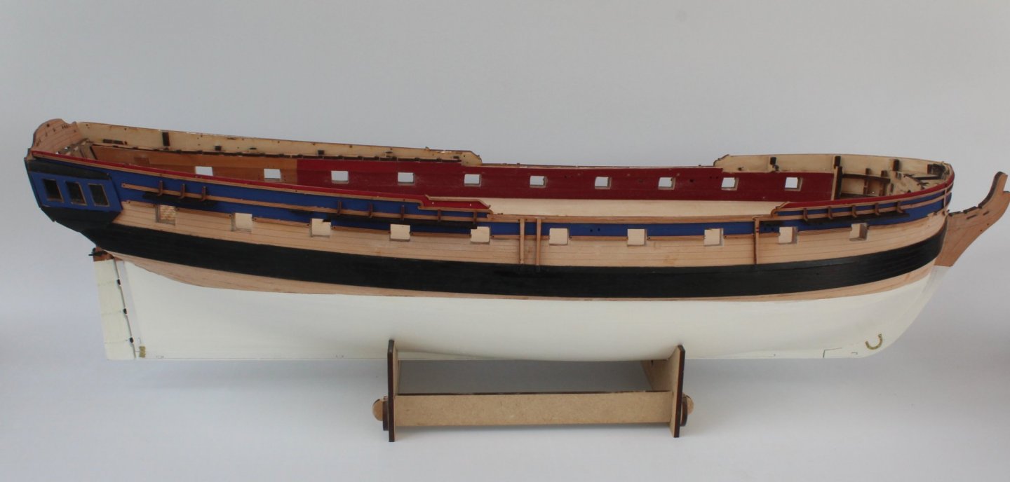
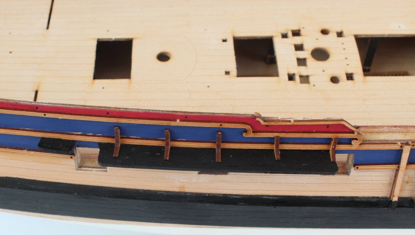
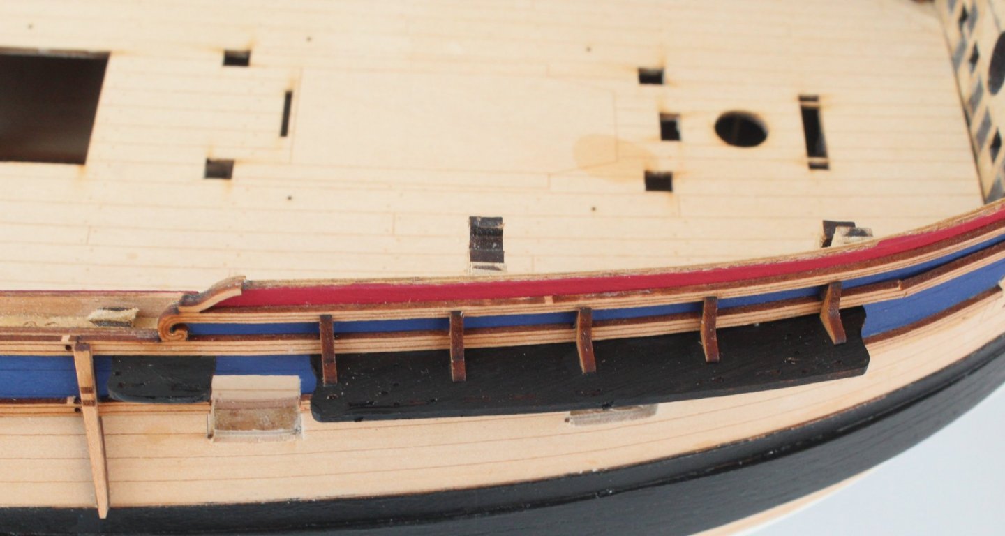
HULL WORK FITTING THE CHANNELS BUILD MANUAL STEPS 262 – 275 LINK TO MY BUILD LOG INDEX Tools Used Craft knife Titebond and CA gel glue Brass pins Varnish Black paint Micro drill Gathering the materials required 373 – 376 (x2), 377 - 381 Assembly Process The channels and channel knees were coated with a thin coat of varnish and then the channels had two coats of black paint. I did sand the sheet with a 1000 grit sandpaper before I applied the varnish. Photo of the channel sheet in the process of being painted The channel parts were then removed from the sheet. Using a 0.6mm micro drill a series of holes were drilled using the guidelines provided and cut off brass puns were inserted with a touch a ca gel. Photo of the mizzen channel ready to be installed. I did test fit the eyebolt slots on each channel also Each channel was then test fitted to the hull and where necessary the micro drill was run through the locating holes on the hull to provide a bit more depth. I found it better to fit each channel and their associated knees at the same time. The edges of the channels were touched up with black paint to complete the task. Next I will start work on the bow grating assembly. Photo of the main mast channels and knees installed Photo of the fore mast channels and knees installed My Sphinx looking like the photo shown in step 275 of the build manual And a side on view for good measure


-
Very nice job so far
-
Thanks, as this is now a prototype build I will probably leave as is. When I start the next one I aim to fill all the gaps
-
Good luck with your second planking, fingers crossed for a fab unpainted finish
- 505 replies
-
- 4
-
-
- vanguard models
- Sphinx
- (and 1 more)
-
Better to paint with a brush and build up the coats gradually as I tend to use too much when spraying from a tin