HOLIDAY DONATION DRIVE - SUPPORT MSW - DO YOUR PART TO KEEP THIS GREAT FORUM GOING! (Only 53 donations so far out of 49,000 members - C'mon guys!)
×


ianmajor
-
Posts
784 -
Joined
-
Last visited
Content Type
Profiles
Forums
Gallery
Events
Everything posted by ianmajor
-
 Jan, The gratings look great. Nice work. I am trying to work out how you made the the capstans.
 -
Edward, Excellent. You can now take the "On Hold" part of your title off - it is "full steam ahead" now.
-
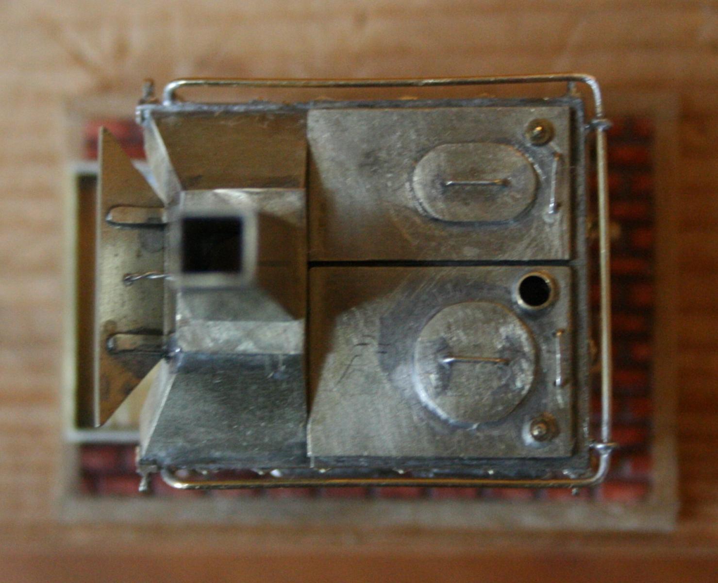
My son then took some photos which cruely shew up the rough edges. The first is the pulley face on. You should be able to see the square edges around the boss produced by the two milling passes to produce each face of the spokes. The second shews the new pulley resting on the tray awaiting the support brackets (complete with stray bit of dog hair). Next up is bracket production which will require a dedicated session with the mill. Should be interesting.

-
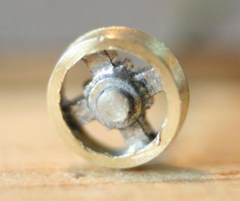
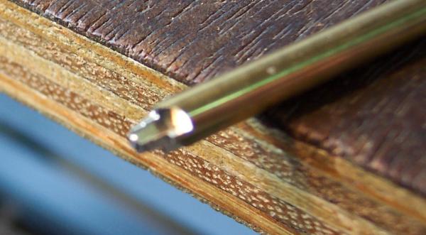
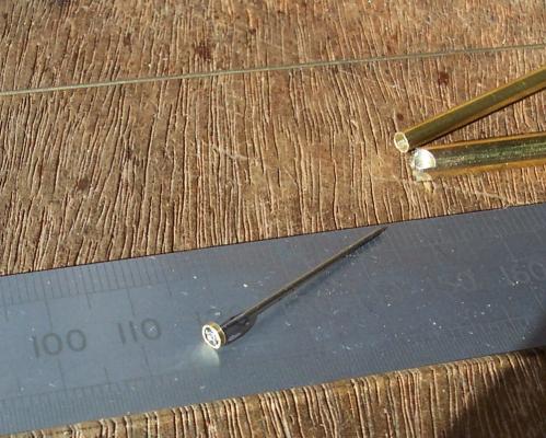
The next item that decided to tackle was the larger pulley for the rotisserie. The stove replica on the Victory shews it as having four spokes. So an interesting session with miller and lathe was called for. The final pulley is 3mm outside diameter. The materials that I used were some 3mm diameter thin walled brass tube for the rim and for the spokes and hub some 5mm diameter rod would be machined. The axle was to be 0.7mm N/S rod. I tried to photo these parts as I made them but my camera is not up to items this small. I should have waited until my son was available with his better camera - but I was impatient to crack on. First I chucked a 10cm length of the brass rod in the lathe and end drilled it 0.7mm. The end of the rod was faced with the tool stopping just short of the 0.7mm hole to leave a raised boss. Then I turned its diameter down to 3mm dia for 6mm length. Then I turned down 3mm length of the end of the rod so that the tube just fitted. Next I tranferred the rod (still in the lathe chuck) to the indexing unit on the lathe. I then milled along the rod from the end. Between each spoke I milled the rod twice to shape the leading edge of each spoke and then the trailing edge. After each pass I rotated the indexing unit 90 degrees. I did all the leading edges first then the four trailling edges after. This left the end of the rod shaped like a cross with a bossed hole in the centre. The following poor photo attempts to illustrate this. I cut a 6mm length of brass tube which I soldered on to the milled cross being careful not to fill in the gaps between the spokes with blobs of solder. This butted up against the 3mm lip. I took the rod out of the chuck to do this to avoid getting flux on it. A quick rinse in dilute caustic solder to neutralize the flux then back in to the chuck on the lathe. I had marked a jaw and the rod so that in lining up the marks up when back in the chuck concentricity would be maintained. I turned the end of the tube back until it was level with the raised boss. This produced some swarf around the spokes that needed clearing out. I parted off the wheel giving a flange width of 0.5mm and finally soldered the pulley on the end of some 0.7mm rod. The next photo shews the 3mm diameter pulley at this stage along with the raw materials from which it was produced.
-
Ferit, Thanks for the sympathy. It looks like you had a good holiday. Your photographs are fabulous. I had a few days away. It rained a lot so I had plenty of time to think about the next steps on the stove. I am baby sitting grandchildren tomorrow so my thoughts will have to wait until Saturday for action. Robert, Thanks for looking in and your encouraging words. Actually your HMS Mars log has been on my "follow" list for some time. I have been looking closely at your lovely elm tree pumps since they will be on my construction list soon.
-
Hamilton, Hum - now lets have a think about that........perhaps I need to have something hanging in front of the grate area to hide the fact that I cheated by using a single piece for its rear. Actually putting a cosmetic fire in the grate would be straightforward - would need one hidden wire to supply DC power, return could be by the metal frame. Mike, Thanks for the like. Perhaps when you come to do your Unicorn stove you will be able to avoid the cock ups and errors that I have made. Over the next few days I will be out of contact with the WWW as I wander around the Herefordshire countryside in the rain. So I will be going very quiet until at least Saturday.
-
Pawel, Thanks for looking in and for your kind words.
-
Hello Peter, I wish my woodwork was as good as my metalwork.
-
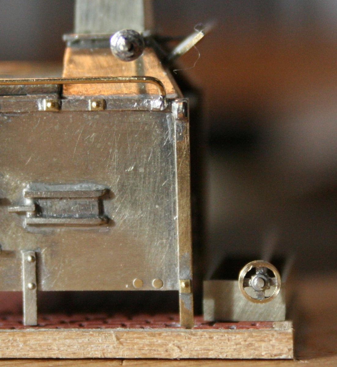
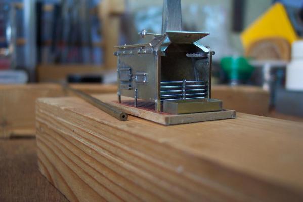
Now on to the rotisserie. I made the top (smaller) pulley from a slice cut off some thick walled brass tubing. In this case the tubing has a 2.3mm outside diameter with a 0.7mm diameter bore. I have various sizes of this type of tube which is useful for making small pulleys and sheaves. Actually I used the lathe to part off the pulley to 0.3mm thickness, plus I included a 0.2mm thickness boss. I soldered the pulley on to a length of 0.7mm diameter N/S rod which fits in to a hole drilled in the stove's hood. In the following photo this pulley and rod are temporarily fitted. The thick walled tube is lying alongside the stove. Well - progress will stop on the stove for a week. I am heading off to deepest Herefordshire with my wife looking at houses - a retirement move.
-
Three photos shewing the rail and centre legs in place.
-
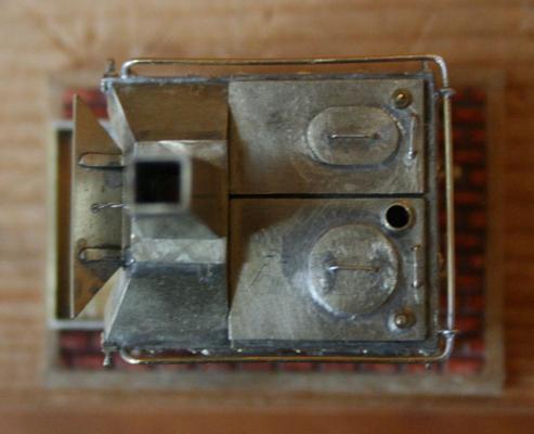
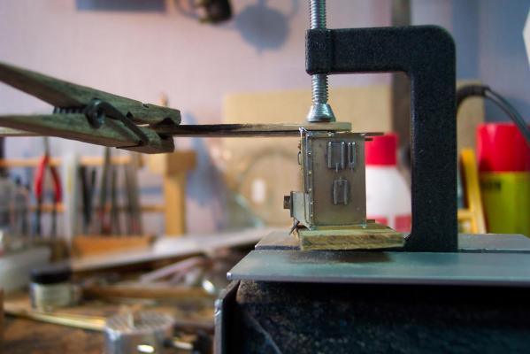
Progress on the stove... The rail around the top of the boilers needs to be shaped and fitted carefully. There are several straight edges on the boiler which lie parallel to the rail, so if it is out of shape or wrongly fitted it will look awful. To get the correct shape I milled a jig out of plywood. The rail was made from 0.5mm brass wire. The next photo shews the jig with the shaped rail - the wire curves down over the end of the jig to make the curved front ends. The rail needs two supporting knobs at the rear of the boilers. For these I made two split pins out of 0.3mm N/S wire. To shape them I folded them around a 0.5mm drill bit, passed the two wire ends through a piece of scrap N/S. I pulled the ends with a pair of pliers to tighten the wire around the bit. To finish the knobs off I soldered the two ends of the wire together. The knobs were then threaded on to the rail and soldered in place. The rail was then offered up to the boilers and the knobs cut to length and bent to fit. The next photo shews the method that I used to clamp the rail in position so that it could be soldered in place. There is a feeler gauge between the rail and the boiler back . This keeps the rail at the correct distance from and parallel to the boiler rear (horizontal alignment). I also used a small piece of 1mm thick N/S to check the gap all around between the boiler top edge (vertical alignment). The knobs should have been fitted in to the corners of the rail but I couldn't get a decent anchor point for them so I compromised by moving them inwards. Having completed fitting the rail I realised that if I had left off the top nuts I could actually have fitted the knobs in the corners. At this stage I added the centre legs. These are 1mm x 0.4mm strip.
-
Hamilton, Now cricket is a game that has some interesting rules............. I will pull together some words on my soldering related tools after I complete the rotisserie.
-
Ed, ...and so it begins. I am going to enjoy this.
- 3,618 replies
-
- 2
-

-
- young america
- clipper
- (and 1 more)
-
John, Thanks for looking in. I am glad that I am not the only one who takes his time over things. I have got all the cosmetic bolts and the lifting ring brackets in place. I am working on the rail that runs around the boilers. This is proving a little tricky. I have made a jig to bend the rail to (hopefully) the right shape. Then the tricky part is fixing it in place so that it is in the right position and does not affect anything already in place. I am trying various ways of holding the rail in place whilst I solder it. When that has been achieved I will put some photos up. Up to this point the stove has been very robust. The items that will be fitted from now will be rather delicate.
-
Ed, Just joining in to your log. It looks like a fascinating project. I will be interested in any different techniques that you may use in this smaller scale.
-
Piet, In answer to your question - yes, it does look like steel plating going on, even more so when it is painted. It is looking very good - or as we Brits would say "It looks a real mean machine".
-
Ferit, Have good holiday. You will probably have better weather than I have at the moment (a lot of Mancunian rain).
-
Mike, Thanks for the words of sympathy. The stove is getting close to completion so I wont be able to put off modifying the the ship's waist for much longer! Hamilton, I am sure the work you do on Blandford at 1:100 suggests that you would have no difficulty in doing what I do on the stove. Besides I haven't finished the stove yet - plenty of time left for me to make a complete cod's of it! Good soldering tools are the thing. I was wondering whether I should add some notes on the tools and materials that I use. Doing this level of detailed metalwork indicated to me that I needed to start wearing spectacles when I managed to burn the end of my nose on the iron! These days I restrict myself to burning my fingers. BTW - I note from your Blandford log that you profess to not knowing the rules of rugby. Shame on you! It was my favourite sport at school. There were a few old scores settled in those matches. It is said that football is a gentleman's game played by thugs and that rugby is a thug's game played by gentlemen.
-
Wacko, Thanks for encouragement. Making a stove on this scale is certainly a good way to go cross eyed.
-
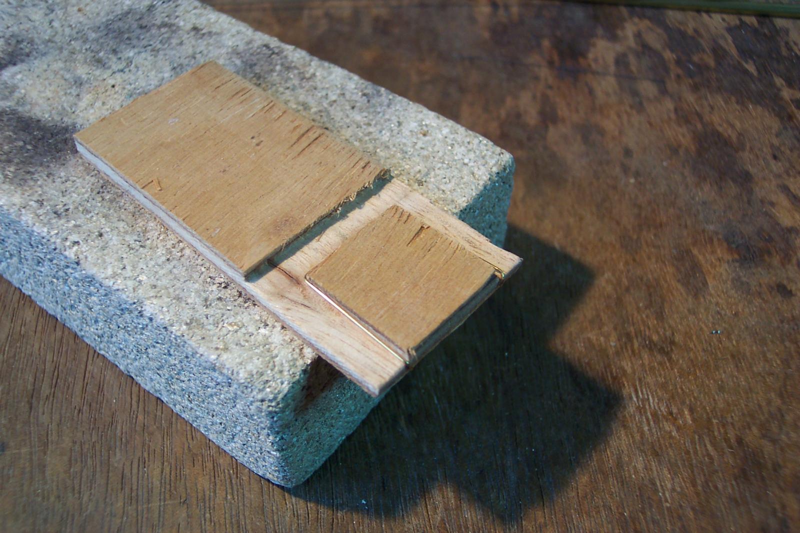
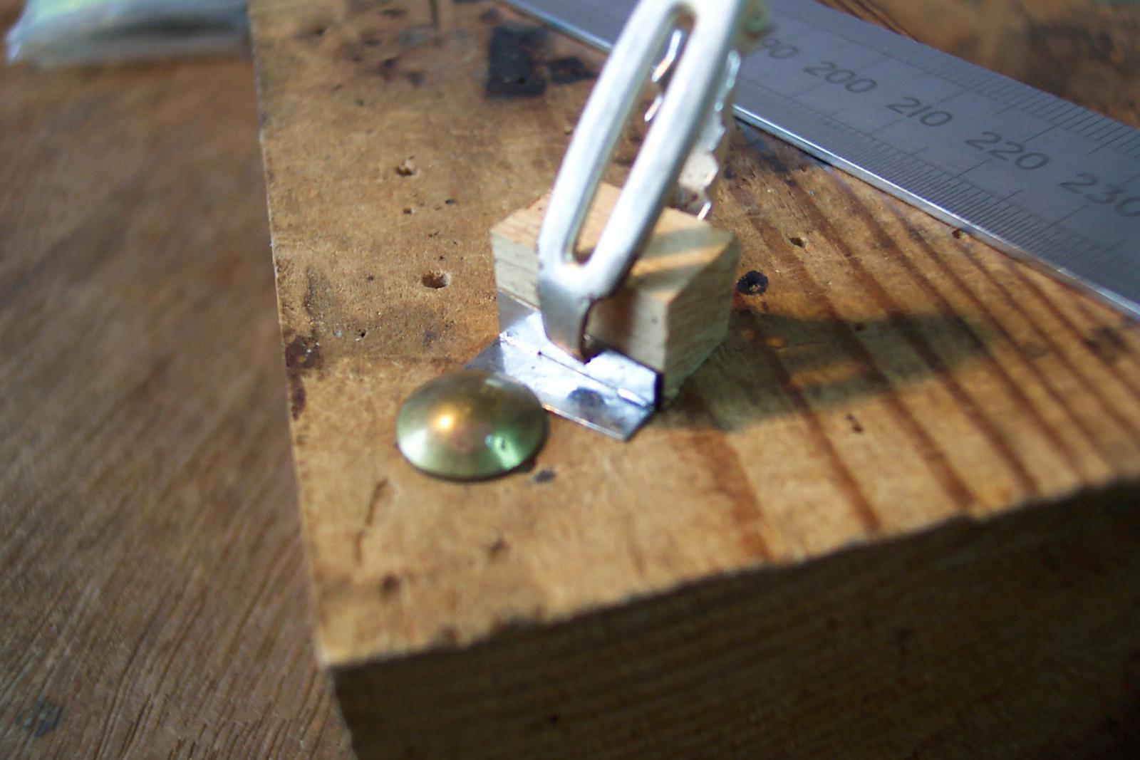
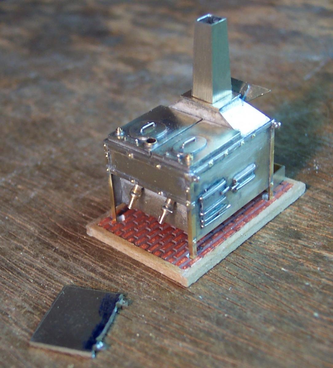
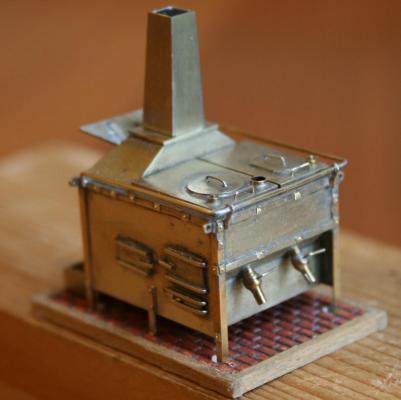
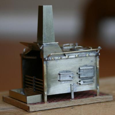
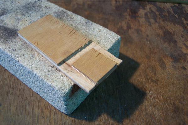
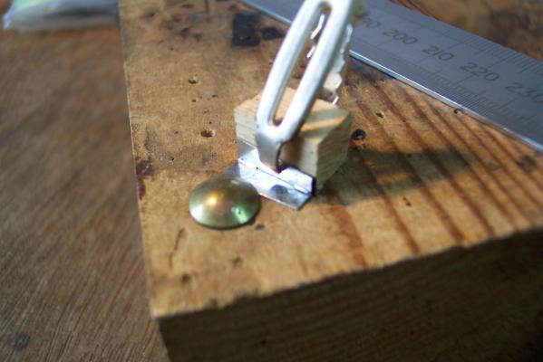
At this point I decided a bit of light relief was required. So I turned to the flue. This will remain detachable until the stove is in its final place. Construction was straightforward since it only consists of four pieces soldered together in a square. These parts were cut from 0.4mm N.S strip 13.7mm wide (the height of the flue). I cut a length of this strip long enough to make one side and an end piece. This was soldered on to the rest of the strip so that both sides and ends could be cut together. The sides were 5mm wide at the bottom and 4mm wide at the top. The ends were 4.5mm at the bottom and 3.5mm at the top. The ends go inside the sides. I soldered an end to each side using a simple jig shewn in the photo below - two bits of wood, a modified hair clip a thumb tack! The two halves of the flue were tacked together, then when I was happy that all was square I soldered up the joints completely. After that relaxing session it was time to solder the cosmetic nuts and the lifting brackets in place. These were a bit tricky.I had to use small shaped bits of wood to hold them in place while I ran solder underneath them. They have a nasty habit of moving when you don't want them to. The next photo shows the nuts in place on the rear and one side of the stove. I have another 5 to add to the other side. The brackets are in place on one side. I have also added the two small handles on the rear of the boilers.The flue is sat in its final place but not fixed. The piece of metal in front of the stove is the bit of scrap with the other two brackets still attached. They have been shaped but I will leave them attached until it is time to fit them to the stove. The next challenge is the rail that runs around the top of the oven. That requires some careful thought. Then it is on to the rotissary!

-
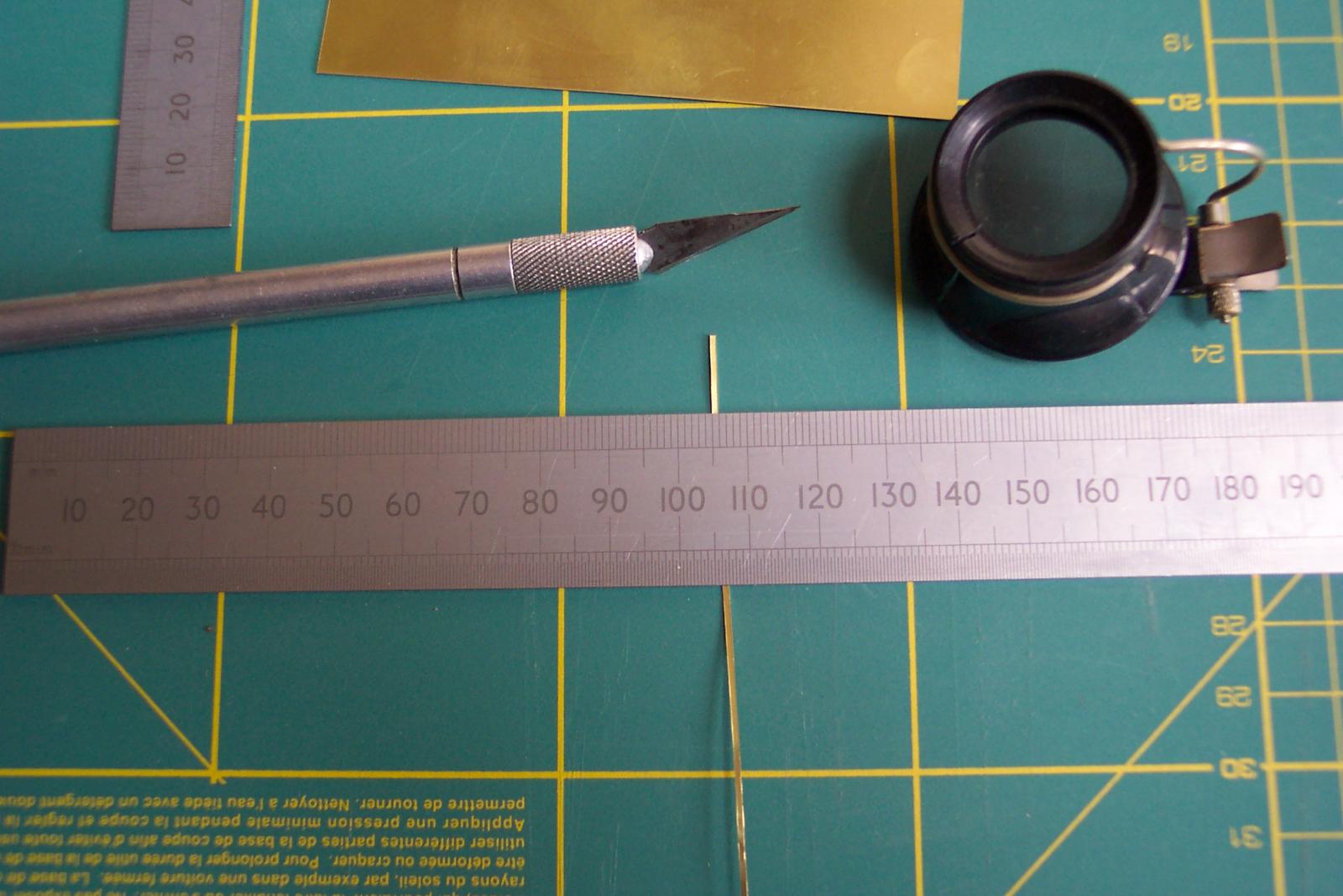
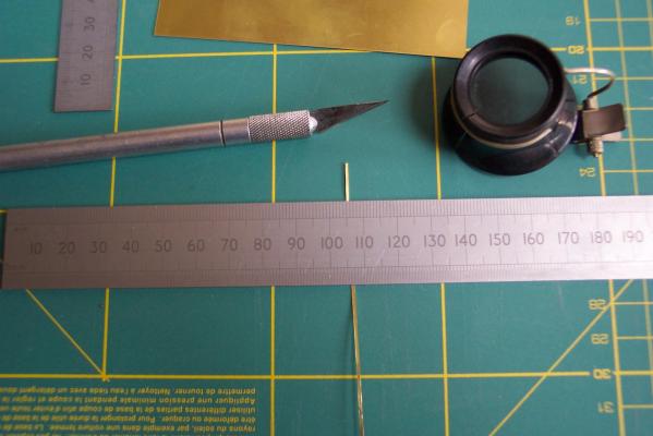
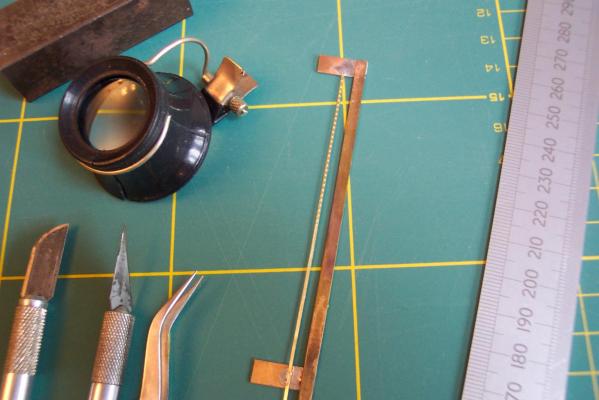
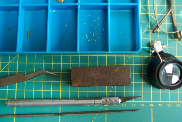
Back to the stove...... Looking at the replica stove on the Victory it has large square bolt heads around the angle iron. Rex Boocock's plan suggests large square nuts with bolt thread showing in the middle. I decided to have go at simulating the nuts. To start with I cut a strip of 0.1mm thickness brass just under 1mm wide. The photo below shows the tools I used to cut the strip. Brass this thickness can be cut with a sharp knife or scalpel. The strip produced had slightly raised edges which I corrected using some fine wet and dry paper (1500 grit). The resultant strip is under the long straight edgw in the photo. Next I wanted to simulate the bolt thread. I have a riveting tool to do this but very small strip tends to flop around. So I soldered the strip to a frame made of scrap as in the next photo. The strip is held taught like the cat gut in a violin bow. I was able to impress a series of indentations at 1.5mm pitch. I also tinned the reverse of the strip at this stage ready for later assembly on to the stove. Then the strip was removed from the frame and the individual squares, each with an indentation in the centre, was cut using the scalpel to 1mm square (well almost) pieces. The small block of steel was used as a cutting surface. Trying to cut on the green mat would tend to crease the strip. The squares produced are in the second container from the right. In the top corners will be 4 lifting rings.Normally I would hold these in place by split pins soldered in to holes in the platework. In this case the holes required would have to go in to the corner joint which would probably snap the bit. So I milled up some small brackets in stead to be surface mounted. Unfortunately I didn't take any photos at this stage. The brackets I produced from 1mm thick N/S strip about 20mm wide. I drilled a row of 0.5mm holes at 1.5mm pitch along the end of the strip centred 0.8mm from the edge. Using a jewelers saw I cut slots between each of the holes to a depth of 2mm. Next I mounted the strip in the machine vice on the miller with the holes horizontal. I made sure the strip was in line with the table's X axis. I then milled the strip equaly on both sides down 1mm from the top edge reducing the thickness containg the holes to 0.3mm. Then at the same setting I replaced the millimg bit with a slitting disk and cut through the strip about 0.3mm below the milled section. As the slitting disk passed each of the previously sawed slots the corresponding "T" section bracket, complete with hole, pinged off. To save them getting lost I threaded thin wire through all the holes before using the slitting saw. So I ended up with a bracelet of tiny brackets. The brackets were then soldered on to the end of a piece of 1mm scrap to allow final shaping.
-
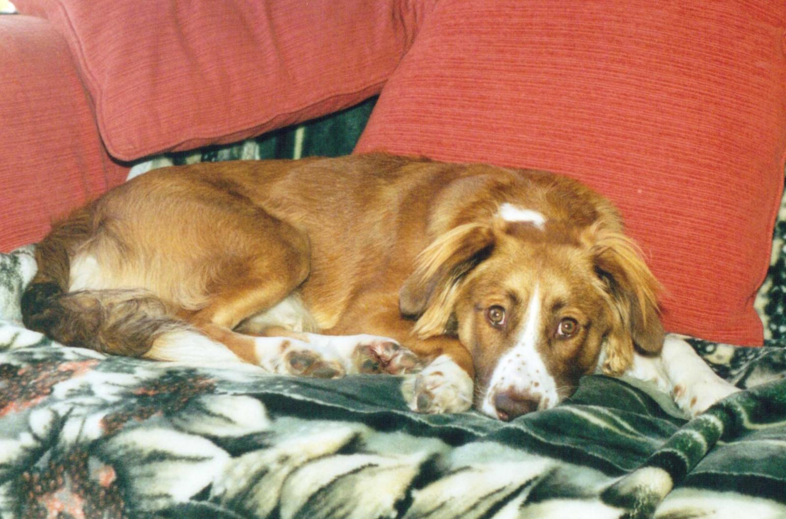
Well before I continue with the stove I will start today's entry with some sad news. Our dog who has been with us for nearly 14 years is no more. He used to sit with me in the workshop. He would give me a worried look whenever I had a rant at myself for doing something wrong or stupid on the model. His look always calmed me down - which was a good thing. I note from various logs that several other members have lost their dogs in the last few weeks including Mark who due to the resultant loss of concentration took a chunk out of his Ship's keel. In my case I was part way through making some parts for the stove. I abandoned these and restarted on fresh parts when the concentration returned. So I bit of a delay in proceedings but I am back on track now. Tom the Dog.

-
Janet, If you want to add photos to your post then next to the "Post" button below the text area there is a "More Reply Options" button. Select this and an Attach Files option appears at the bottom of the text window with a "Choose Files" button. Click on this and you will be able to submit some photo files (keep it below 2MB per submission). One icon per submitted file will appear in the Attach Files area. You will notice that against each icon there is an "Add to Post" and "Delete". Position the cursor in you text where you want the photo to appear then click on "Add to Post". (If you don't do this last action the photos appear as thumbnails at the end of your posting). You will also notice at this point that the pictures only appear as a name in the text box. If you want to see what your photos look like in the text before publishing then hit the "Preview Button" just below the text box. It would be interesting to see how you are getting on with your build so it would be great if you started a build log in the kit build area which could include your photos. There is a posting about how to go about this at http://modelshipworld.com/index.php?/topic/53-before-you-post-your-build-log-please-read-this-starting-and-naming-your-build-log/ Hope this helps.
-
Hamilton, Nice looking little boat. I will be building one in the not too distant future and am interested in this. If I understand the photos correctly there are 4 formers that hold some of the frame parts in shape whilst they are attached to the keel and whilst the planking is added. The rest of the frames are added after the planking is secure. Have I got that correct? Was it at this point that the formers were removed? If so this is a different approach to the usual frames with detachable central part. The use of formers looks to me to be more suited to the smaller scales and hence ideal for what I will be doing.
-
Hamilton, Many happy returns of the day. 42 is a good age to be. You will still have the energy of the young plus you will be a long way towards developing the wisdom of the not so young.