HOLIDAY DONATION DRIVE - SUPPORT MSW - DO YOUR PART TO KEEP THIS GREAT FORUM GOING! (Only 53 donations so far out of 49,000 members - C'mon guys!)
×


ianmajor
-
Posts
784 -
Joined
-
Last visited
Content Type
Profiles
Forums
Gallery
Events
Everything posted by ianmajor
-
 Hamilton, Your beautifully constructed hull is now set off well by the masts and rigging. I agree with Ferit on the low level shots. They give a real sense of power.
 -
Hamilton, a pleasure. I have started the cleaning process on the stove. I eventually got my Shiny Sinks from the local hardware shop - I think there is a lesson in that. The Shiny Sinks highlights any surface solder, it also highlights any poor joints. Thus far only had the joint at one end of the spit fail (that had a minute bit of solder) which I have resoldered. I have cycled around giving the stove a clean with the Shiny Sinks, then a mechanical scrub with the scratch brushes twice then a final clean. It will dry overnight then if an inspection is OK I will start on the blackening process. I hope that goes well. I have also produced a diagram for the still/condenser and am preparing some copper rod for it. After more than 4 months the end (may) be in sight!
-
Daniel, Clever stuff. Must remember that when I start rigging.
-
Very nice deck planking. She is progressing very well.
-
Piet, I think the T-bar/boom modelled in the raised,rigged position lifting out the dingy would be a delightful and probably unique feature on a model submarine.
-
Thinking about my reply to ZyXuz on the minimum items for soldering reminded me of something a (sadly now deceased) friend told me. He made brass models of locomotives to order and was very good at it. He also did demonstrations at exhibitions. At one of these he ran out of the acid flux in the middle of the day and none of the traders at the exhibition had got any on sale. So he went to a drinks machine and got a can of Coca Cola which he used for the rest of the day as his flux. He told me it gave good joints and only left a small sugary residue that was easily washed off with water. He recalled with great glee the look of horror on the faces of two young mothers as they ushered their children away after realizing what he was doing!
-
Thanks guys for kind words. Ferit, My grandfather was a great believer in "teaching them young" - often to the horror of my grandmother. My first attempt with the gas fired iron resulted in me burning its wooden handle. I also managed to have an "impact" on the household furniture which didn't go down well with my parents. ZyXuz, I could have done the whole job with just the Antex station, the 145 solder, the "Red" flux, one of the scratch brushes and the three cornered scraper. But I am geared up for more specialized soldering tasks. The ERSA and the various solders make the job so easy - so why make life hard for myself? Greg, Thank you for the compliment. An artist is an innovator. I simply copy other peoples' ideas. I fear, therefore, I am a practitioner rather than an artist.
-
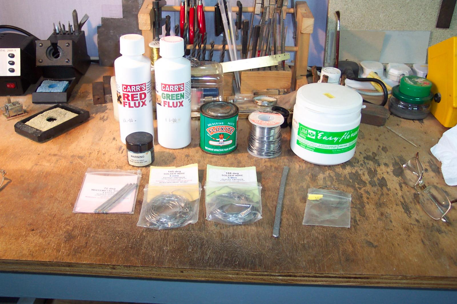
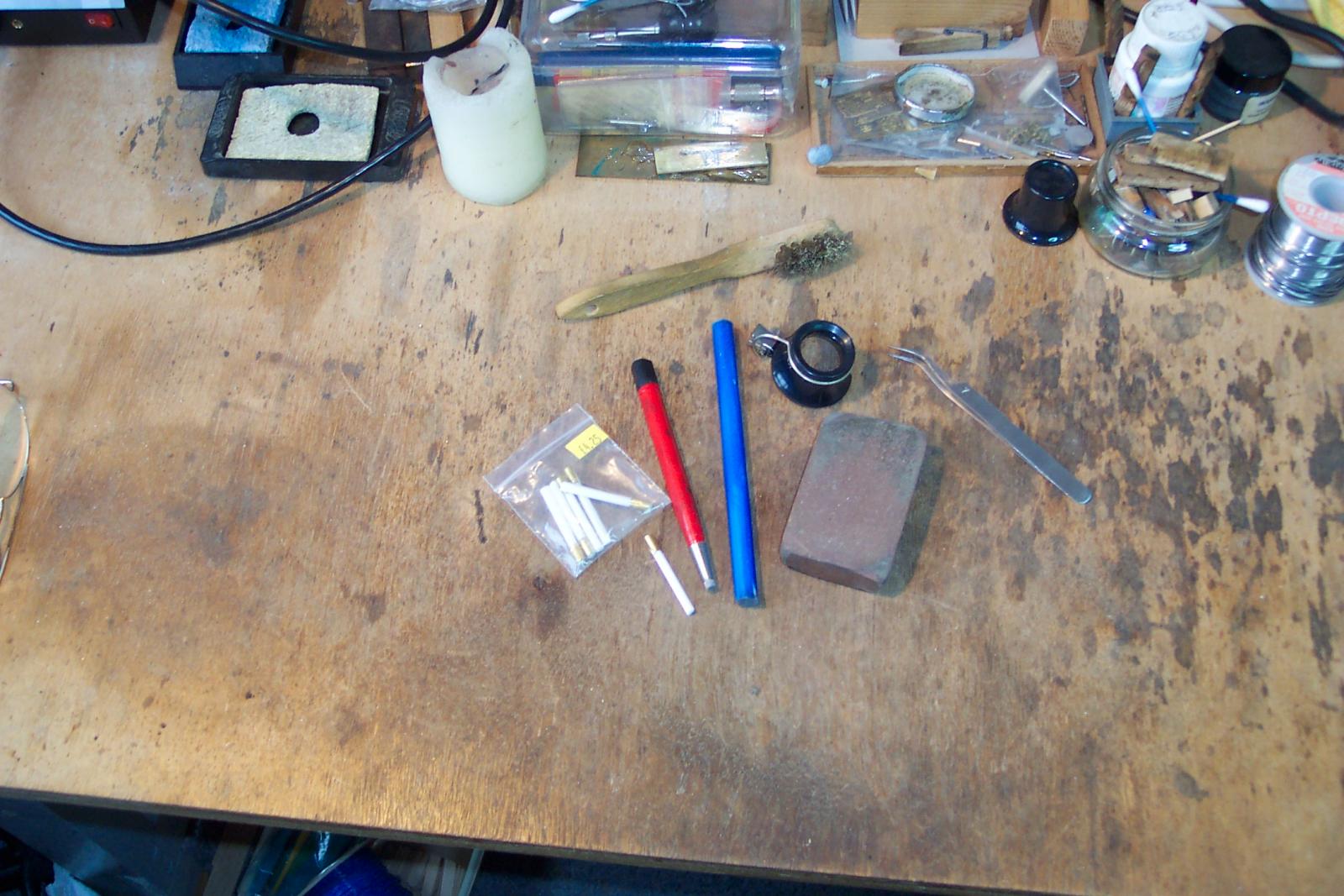
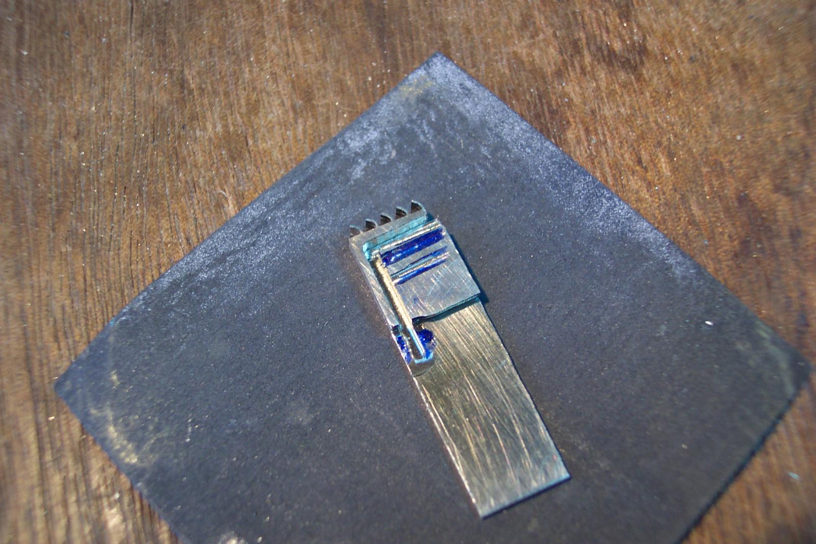
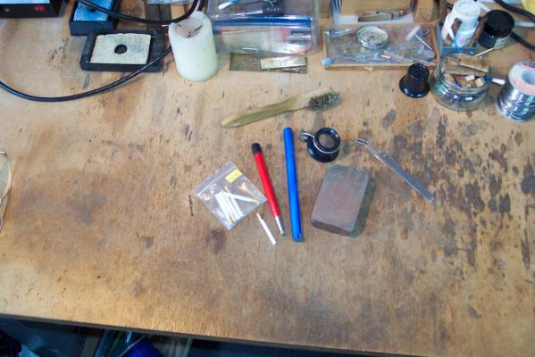
I thought I would shew the solders and fluxes that I use. In the front row the solders (from left to right) are 70 deg, 145 deg, 188 deg, 225 deg (the strip) and some silver solder. Behind in a jar is solder paste plus a reel of 60:40 solder. The latter I mainly use for electrical wiring since it has a flux core. Behind are the fluxes. I generally use liquid acid fluxes applied with a brush. The "Red" is best for Brass and N/S, the "Green" for whitemetal and steel. I occasionally use the flux paste from the green tin. The white container holds my borax for silver soldering. After a soldering session with the acid flux I give the work piece a wash in dilute caustic soda (normally used for cleaning drains). Without this the model would start to turn green in a few hours. Finally a picture of items used for preparing/cleaning the metal. Another big cause of poor soldered joints is grot or a coating on the metal. I tend not to use solvents to clean the metal. Instead I use glass fibre scratch brushes which along with the acid fluxes go a good job.The photo shews two of them. The blue one is a bundle of glass fibres held in a plastic sheath. I use it on fairly large areas such as sheet metal by just scrubbing away with its end (the plastic wears away). The red one is like a propelling pencil except it has a small bundle of glass fibres in stead of a lead. I use this around detail and along the area where a joint will be made.The plastic packet has refills for it. I also use these scratch brushes (along with a three cornered scaper) to clean off excess solder. A contra to these items is that they shed small lengths of glass fibres which if they get in to your fingers really hurt and they are hard to spot. So a couple of tools in the photo are the jewelers lense and fine tweezers to remove these bits of glass. Rather than get the fibres in my fingers I regularly use the old suede leather brush to clean the fibres directly in to a bin. (No blowing else they go in your eyes - no sucking either.) The other item in the photo is a garryflex abrassive cleaner. It is just a large (pick the word carefully here) eraser. This is great on large areas of metal but leaves a lot of bits everywhere. Now - back to cleaning the stove.............

-
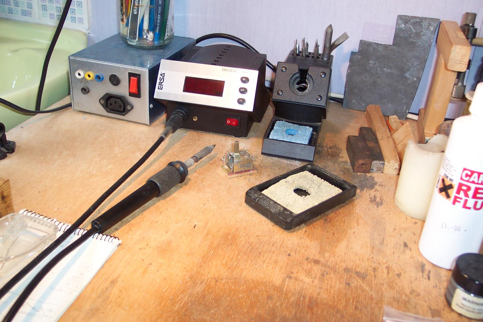
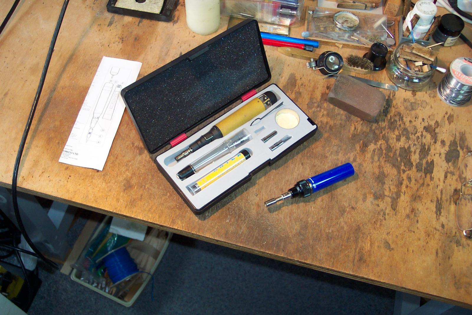
This photo is of a lovely piece of equipment. It is an ERSA Digital 2000. It is a soldering station that makes soldering a delight - in fact it is the only unit that I used on the stove. (Which is sat in front of it) The organisation selling this type said they were made to US military specifications. No matter whether this is true or not it is top notch. It has loads of grunt, is programmable to give different heating profiles and has a temperature display so you know exactly what is going on. It gets a lot of heat quickly in to a small spot getting promptly up to the temperature that you want. So you can readily solder small bits successfully before the heat has a chance to spread to the rest of the joints. Why do you need an iron with plenty of grunt? One of the causes of bad joints is the solder not being fully melted when the joint is made. Solder is an alloy that has two important temperatures - the solidus and liquidus. Below the solidus temperature the solder is totally solid. Above the liquidus temperature the solder is totally liquid. Between those temperatures the solder is in a semi liquid plastic state. If your iron doesn't get the work above the liquidus temperature a joint will be produced but it won't be any good. Equally if you move the parts as the solder is cooling through this plastic state a bad joint will also result. By way of an example, plumbers 60:40 solder has a solidus temperature of 183 deg C and a liquidus temperature of 191 deg C. There are a few solders where the two temperatures are the same - these are refered to as eutectic solders. For silver soldering I have a couple of torches as shewn in the next photo. These sit with me in the workshop. I also use these for annealing. If I have a bigger job then in the garage I have a medium blow torch and a large one on a gas bottle.


-
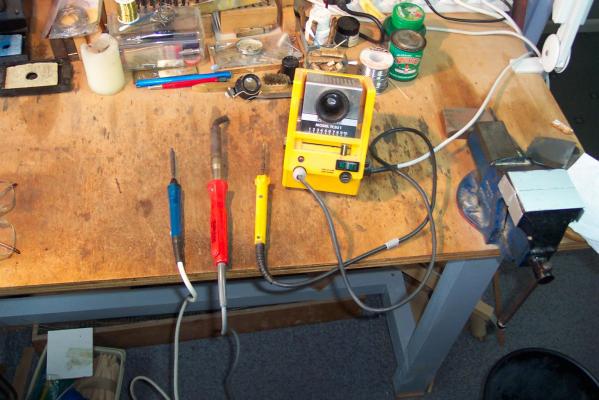
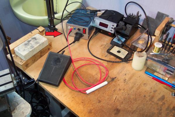
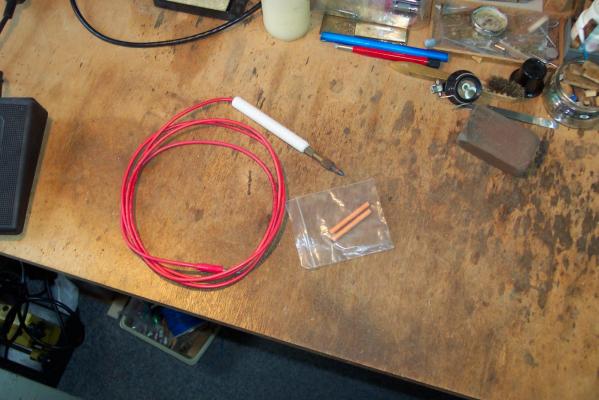
Whilst waiting for the cleaning material for the stove I thought I would add a few words about my soldering equipment - hopefully it might prove useful to somebody! I had my first soldering iron when I was 10 years old. It had been my grandfather's so was pretty ancient even then. It consists of a large octahedron shaped bit of copper 3 inches long for the bit. The bit is riveted to a 12 inch long steel rod with a wooden handle at the other end. It needs a gas fire heater to heat it up. In practice a pair would be used - one being heated up whilst the other was in use soldering. I have seen delicate work done with these monsters - the last time was in 1986. I still have it somewhere. The next photograph has a selection of the next generations of irons that I owned. The one on the left has a copper bit that needs regular dressing with a file. I used to use it for detail work but not now. This is the only one I lend out. The middle one (red) is a 75 watt Weller iron. It has plenty of grunt for the heavier jobs and I still use it on large components in my railway loco modelling. This type of iron comes with a coated bit that doesn't need dressing - just cleaning with a damp sponge - in fact taking a file to this bit ruins it (I loaned a similar one to a colleague who did just that). The third iron in the photo (yellow) was a big step forward. It is an Antex TCSU1 soldering station into which I have a 30 watt iron plugged (you can plug more powerful irons in to it). The slider control allows the temperature of the iron to be varied. Sadly there is no temperature indicator. Why would you want to control the temperature of an iron? For me two reasons. The first is that it can be used to solder whitemetal castings without fear of melting them. The second is that low melting point solders contain Cadmium. If you heat this type of solder above 321 deg C you will start to boil the Cadmium off - and then inhale it - not good. I still use this soldering station for jobs where access is restricted. ++++ The next photo shews a Resistance Soldering Unit usually refered to as an RSU (indicated by the arrow). This is a unit that I made myself and is basically a step down transformer. This type can be bought commercially so I I won't describe its construction - I don't want agrieved spouses accusing me of electrocuting their loved ones! It has a black cable with a crocodile clip on the end, a red cable with a probe on the end and the black object in front of it is a foot pedal. To use it you put a sheet of metal (preferably steel) on the bench and connect the black cable to it. You place the items you wish to solder together on top of this plate with solder paste between them. You then put the probe (red wire) on to the items to solder, press the pedal for a few seconds, and the joint is made. Whilst the pedal is pressed current flows through the joint heating it up. This unit is great for soldering small etched detail parts on to larger parts. Two advantages. One - when you take your foot off the power the probe goes cold, so you can hold the soldered detail in place with the probe until the solder sets. The second advantage is that there is no solder on the probe so the detail won't disappear under a blob of the stuff. One thing to watch out for is to ensure you have taken your foot off the pedal before lifting the probe off the work. If you do get this wrong you strike an arc which immediately burns the detail away. Been there - done that. The next photo shows the probe in detail. Clamped in the end is a carbon bit. The plastic bag contains two spares. Basically they are carbon rods with a copper jacket. To get (or renew the point) you simply sharpen it with a pencil sharpener.
-
Thanks Ray. Hum - I am now starting to think perhaps it ought to go in to a battle station model. But if I did that I would have to make another for the Unicorn!
-
Hello Mike, It would be a small show case, I would probably lose it down the back of the settee. I am taking the opportunity provided by wait for cleaning material to tidy up the workbench - and to find my piece of copper rod to make the condenser. Now that will be interesting build since copper is likened to carrots when it comes to turning it on a lathe.
-
Mark, Thanks. It is a coincidence that your smiley face graphic has a pint pot in his hand. My youngest son is visiting us at the mo and is in the middle of some home brew. The way some of it is churning and bubbling away I am beginning to wonder whether my next update might come from the dark side of the moon!
-
Ferit, You should see my hands - real agricultural ploughman's hands!
-
Ferit, It looks good to me. How big is this mouse?
-
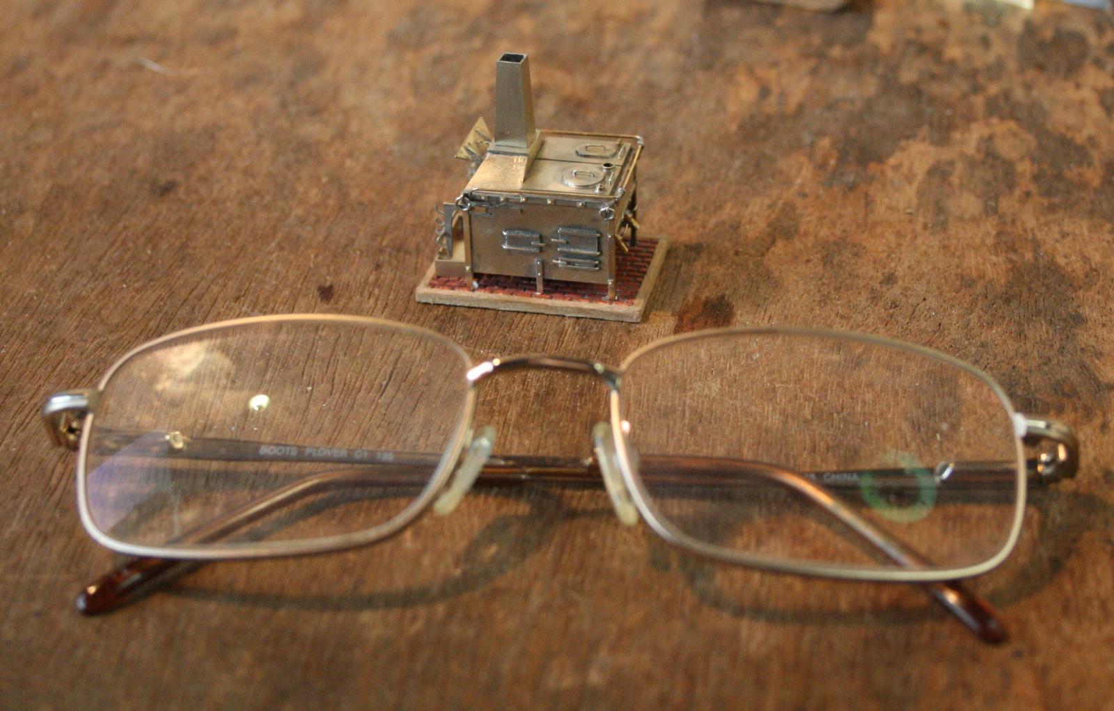
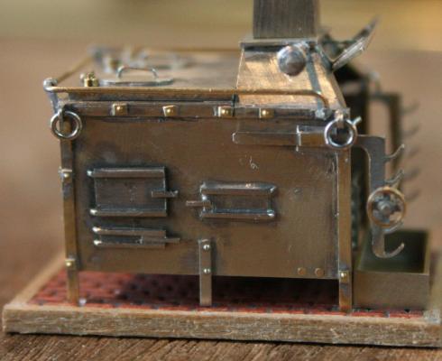
.........but first we need a kettle to boil the water - and here it is, ready to go. It is a scale 12 inches high and is based on a kettle we used to use on our Scout camps. It was a straightforward, though fiddly, turning job. I started with 5mm diameter brass rod. Faced the end then turned a length down to 3mm. Using the top slide set over to taper the end using a left hand tool, I turned the lid and its knob (effect). Then reverting to the right hand tool I tapered the side. Finally I parted it off just over 3mm long. To do the rest of the work I held it in the jaws of a wooden clothes peg, which was itself then held firmly in the vice. (The wood of the clothes peg molded to the taper, the vice gave the grip required). I then sawed a slot in the bottom of the kettle body. The spout was made from 0.5mm wire soldered in to this slot. The spout was bent to shape but not shortened yet. (If the part pings off the bench, it is a lot easier to find).The handle was made from a loop of 0.3mm wire which was soldered to each side of the lid. The spout was then cut to length. It needs cleaning, there is a small amount of filling (a small gap left by the slot) then blackening. OK,OK - I know - I am now completely bonkers. To finish off this session, and to indicate the scale of the stove here is a picture with it posed next to my spectacles.


-
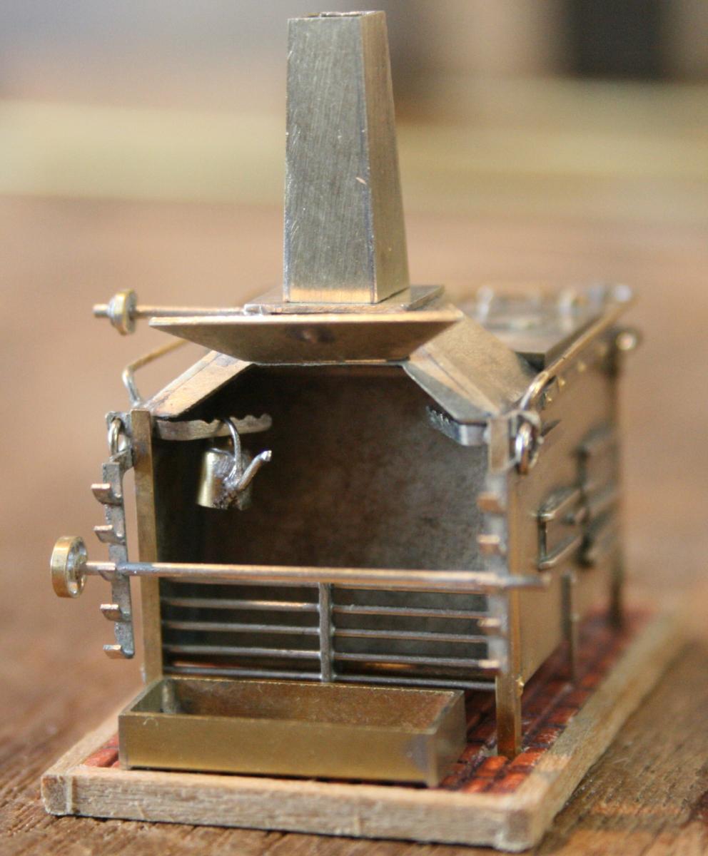
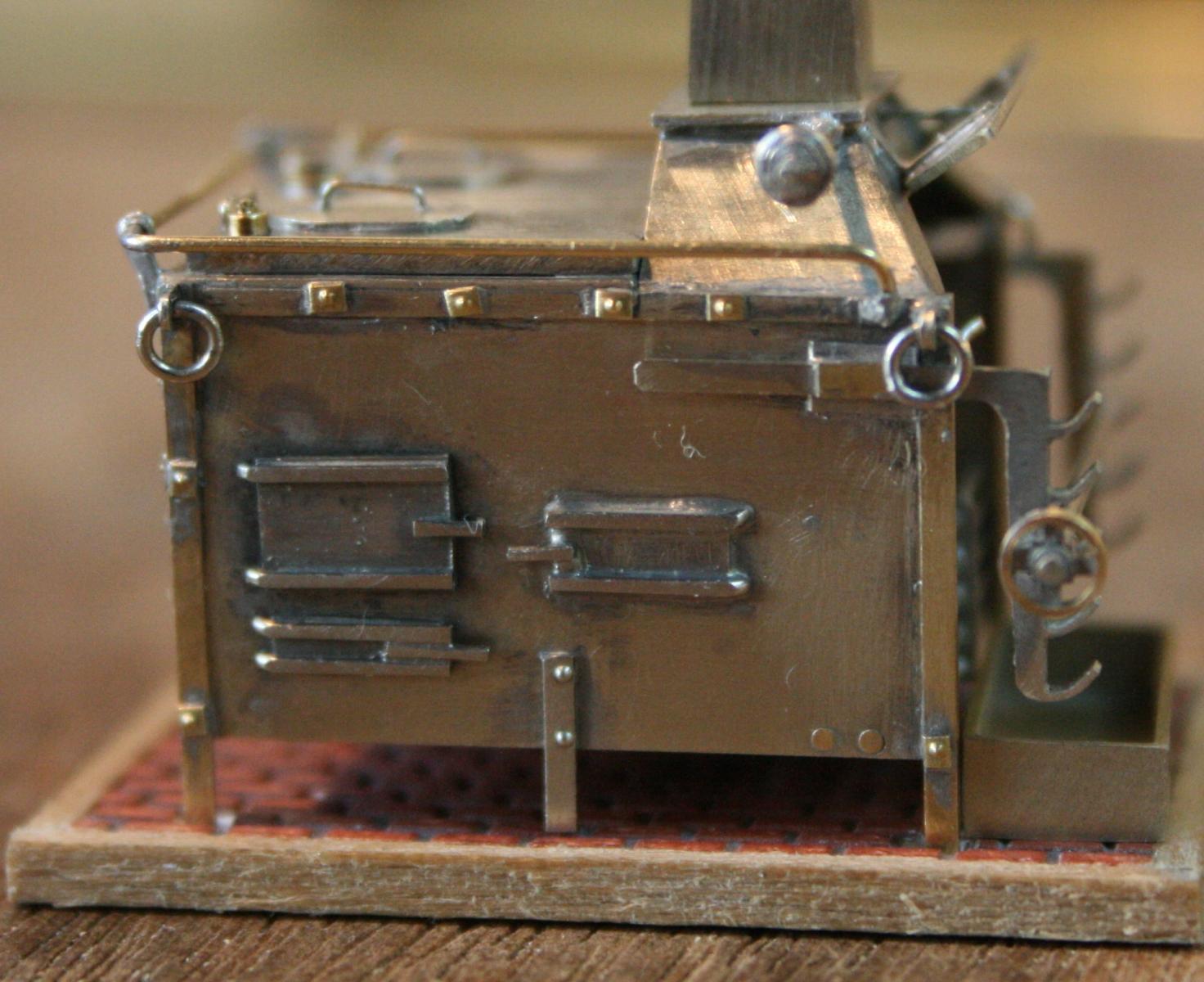
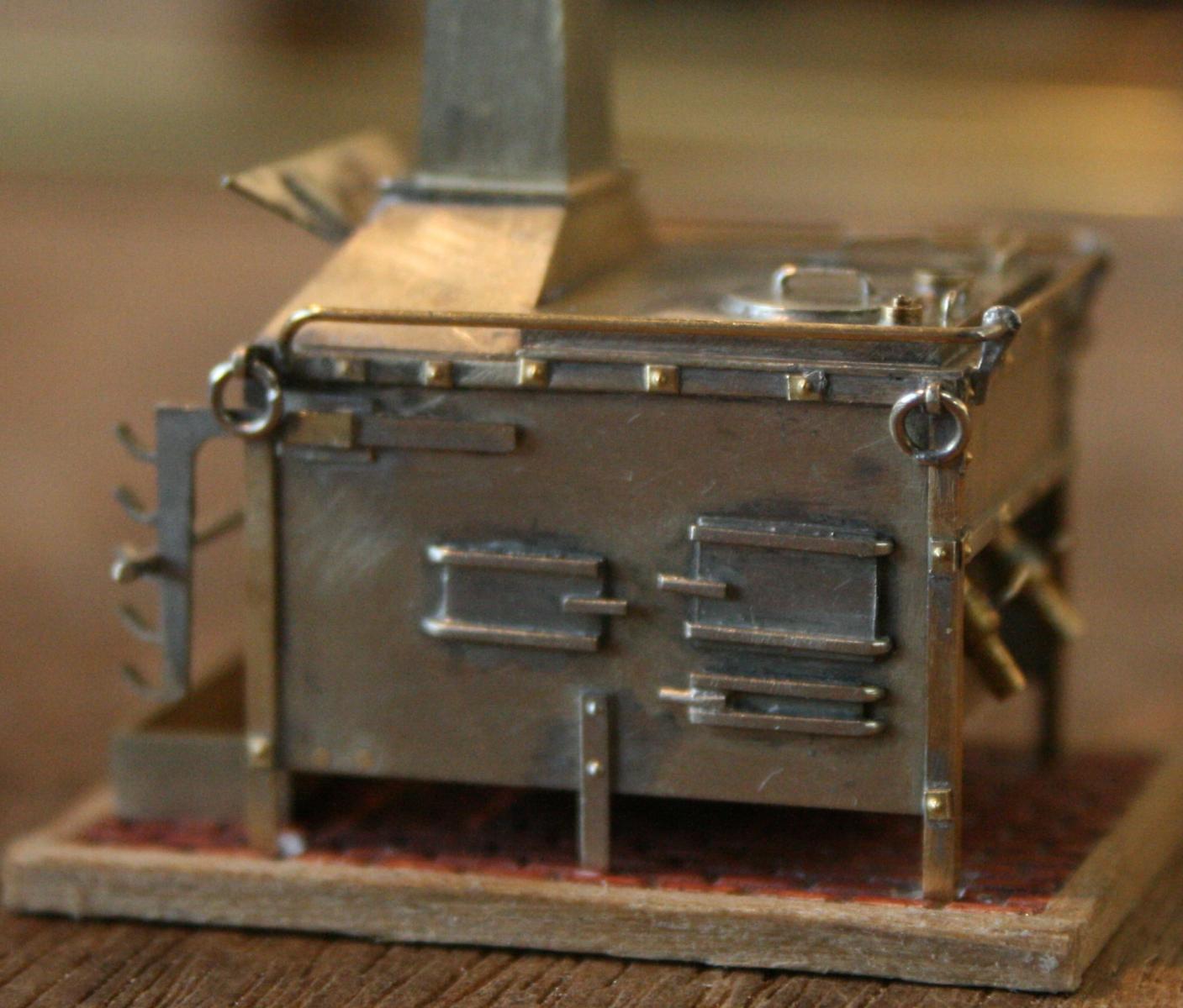
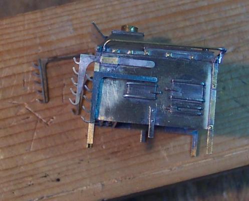
The first job was taking the MK I brackets off and fitting the new MK II versions. They look a lot better to me. With these in place I could then fit the lifting rings. Again looking at the stove on Victory I decided the ring diameters were 1/6th of the height of the side. I tried producing rings on a number of different diameter formers (brass rod with a hole in the end ) using various type of wire. I settled on 0.5mm N/S wire wrapped around a 1.5mm diameter former. This gave me rings close to the 2.3mm diameter that I wanted. Four of them were fitted to the stove. I also permenantly fitted the spit/bottom pulley and the top drive shaft. I will attempt to replicate the chain using 0.1mm wire after the stove has been blackened. I will be using super-glue to fit the chain which I felt could affect the blackening process at this stage. Two photos shewing the current state of play: At this point I was going to give the stove a good clean ready for the blackening. I like to clean the model 2 or 3 times using a cleaner called Shiny Sinks. I gives a mild scouring to the surface, it also has acetic acid which brings brass/copper/N/S up beautifully. It also works well on sinks - which is why I discovered that we haven't got any. Worse all the supermarkets have stopped selling it. I will have to order it from Amazon, which will take a few days. In the meantime Hamilton, what about that nice English cup of tea............

-
Hello Ferit, Actually my wife is happy for me to be in the workshop. It stops me from getting under her feet! ........... ......so I was in there today.
-
Thanks Hamilton. Bit of quandary. I am making the stove so that I have something to put in to the waist of the ship when I open it up! Quote from my wife to one of my sons "The amount of time he has spent in the workshop on that thing he could probably have made a full size one".! She is probably right. Put it down to my obsessive nature. I have been trying a couple of sizes for the lifting rings to see which looks right. These will be some of the last items on the main part of the stove. The only other big item is the still/condenser.
-
Cutty Sark by NenadM
ianmajor replied to NenadM's topic in - Build logs for subjects built 1851 - 1900
Thanks. There are some nice films of shipping in the Iron Gates but nothing (that I could find) predating the construction of the dam. I will keep looking. Somewhere in the archives of the old Yugoslav state TV the film will be waiting. I will keep looking. -
I will risk being accused of repeating myself - that carving is stunning. I wish I could do the same. The framework is great as well.
-
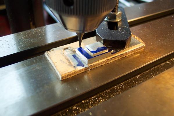
Thanks John. It is a fairly straightforward piece of milling. Main thing is to take it steadily with small cuts. I always have to resist impatience as I get to the end of one of these jobs. More than once I have done dozens of passes with the mill bit then got to within a couple of passes of the end and gone OK I can do the rest in one final big cut .......bang....several hours work is wrecked.
-
Mike, Nice to see you back in the (Badger) modelling harness! The buoys are impressive. Colour looks spot on to my eyes.
- 153 replies
-
- 1
-

-
- badger
- caldercraft
- (and 1 more)
-
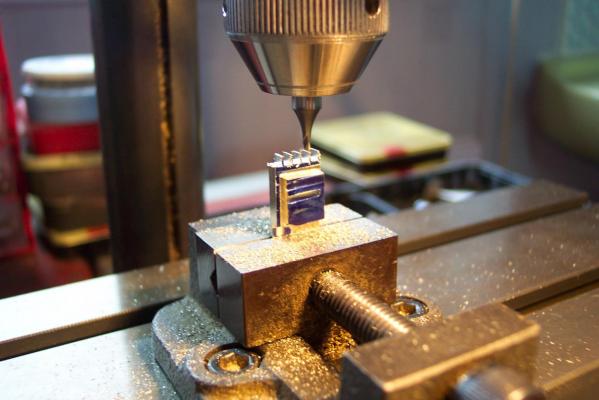
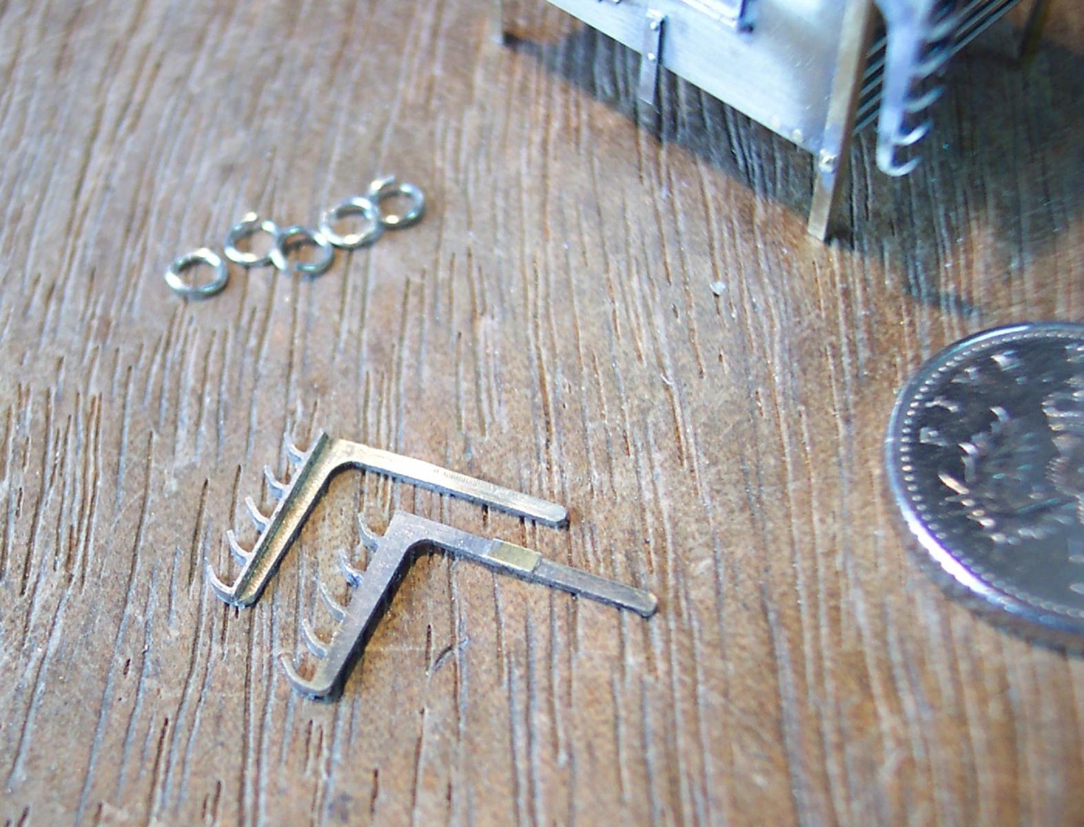
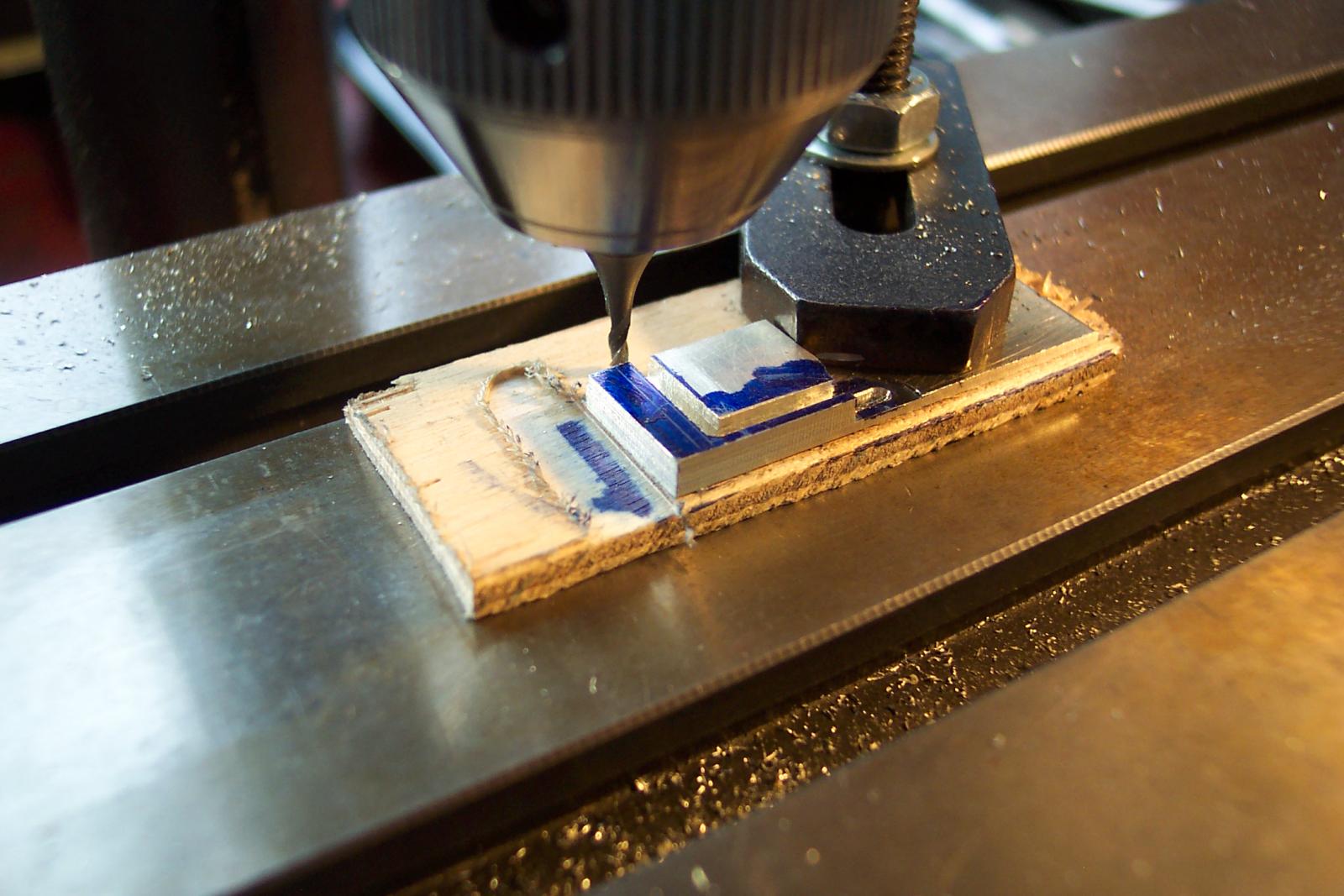
After unsoldering the three pieces, the new brackets were soldered face to face on a piece of scrap brass and the brackets milled in to give a "L" section cross section exactly as per the MK I versions. They were cleaned up and final shaping was done with a file.Small pieces of 0.1mm shim were soldered on to the sides to represent the clamps. Then they were compared with the MK I versions. The next photo shews the MK II brackets placed near the MK I version for comparison. I feel happier with these. (Edit - I have replaced the first of the above photos with a better one.) Now it is time to pluck up courage to pull the MK I parts off and fix the MK II in place. I think a good night's sleep first.

-
I switched to the 1.5mm mill bit to cut the profile of the brackets by cutting an "L" shape. Each pass I only cut to a depth of 0.1mm to avoid straining the bit. After cutting down through the two bracket pieces but not the support piece I rotated the work piece by a few degrees so that I could mill a taper on the rear edge of the vertical part of the bracket. Next it was in to the miller's vice to cut the "fingers" then bending them to shape as on the MK I versions.