Stuntflyer
-
Posts
1,197 -
Joined
-
Last visited
Content Type
Profiles
Forums
Gallery
Events
Everything posted by Stuntflyer
-
 Dr Per, Jack, I found the Dremel Workbench here. . .http://www.ebay.com/itm/like/221495363403?item=221495363403&lgeo=1&vectorid=229466&rmvSB=true
- 2,191 replies
-
- 2
-

-
- confederacy
- Model Shipways
- (and 1 more)
-
Jeff, If you look at my photos on page 1 http://modelshipworld.com/index.php/topic/8494-mayflower-by-stuntflyer-mike-model-shipways-532-scale/ you will see how I did the bulkheads. The first bulkhead was done using four 3" angle plates. The weight of the plates was enough to hold the first bulkhead in place. Instead of trying to clamp the remaining bulkheads to the former, I squared the bulkheads to the former using two angle plates and a few clamps. I did them one at a time until the glue was set. You should be able to add a bulkhead every 15 minutes with this method. It is important to have a slight amount of play so the bulkhead can move side to side before gluing. This will allow the bulkhead to maintain a 90° angle since the PVA glue will swell the wood and tighten the fit. Using this glue allows time to adjust the bulkhead-former vertically before the glue sets. I have never used the MS fair-a-jig so I can't tell you how to make it do what you want. The method I described has been used by others with good results. If you don't have angle plates you could substitute something that has a 90° angle. Hope this helps! Mike
-
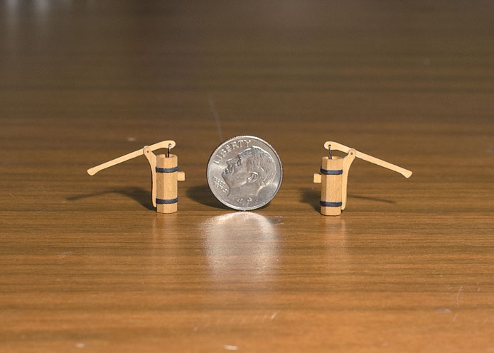
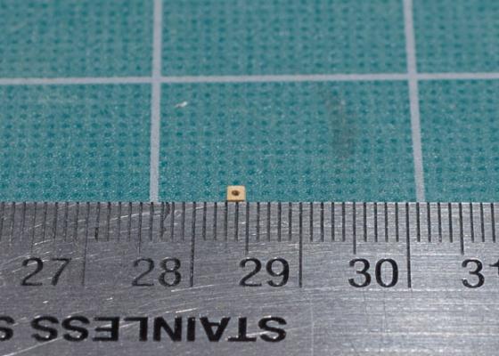
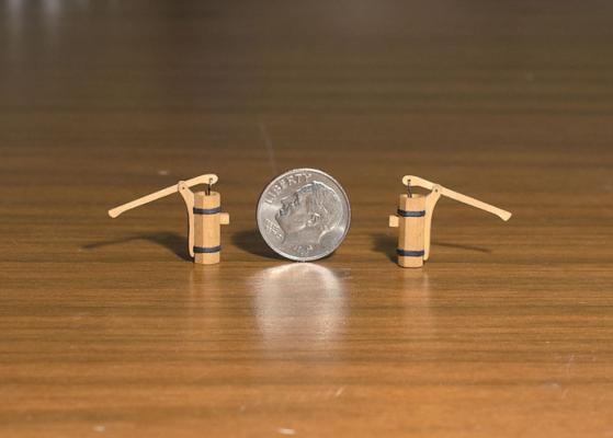
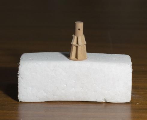
● Pumps: The pumps were made according to the kit instructions with one change. When I tried making the main cylinder from 3/16" dowel the diameter ended up too small according to the plan. I was successful when I used 3/16" square strip and a "V" groove jig to hold the strip in place while forming the eight sides. The black bands were made from card stock. I glued the tiny spouts to a piece of scrap wood with PVA glue to hold it while sanding them with my newly acquired "True Sander". I dipped the spout into boiling water to release the glue. This photo shows how small the spouts are. Finished pumps with a coat of Wipe-on Poly.
-
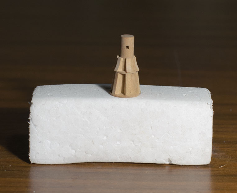
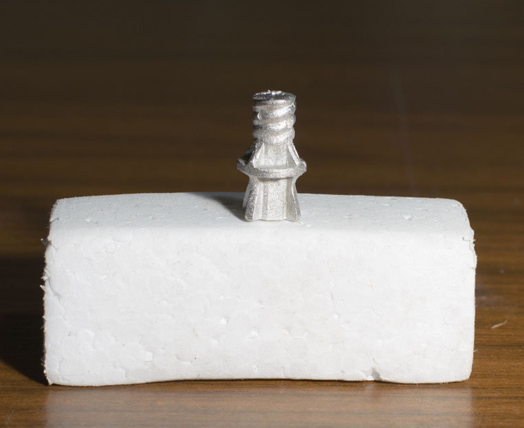
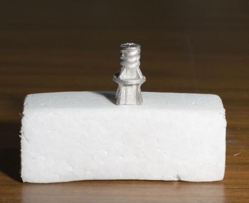
● Capstan: While waiting for the tools to arrive I thought it might be a good opportunity to scratch a few parts. Here is the first one, the capstan, compared to the kit supplied one.
-
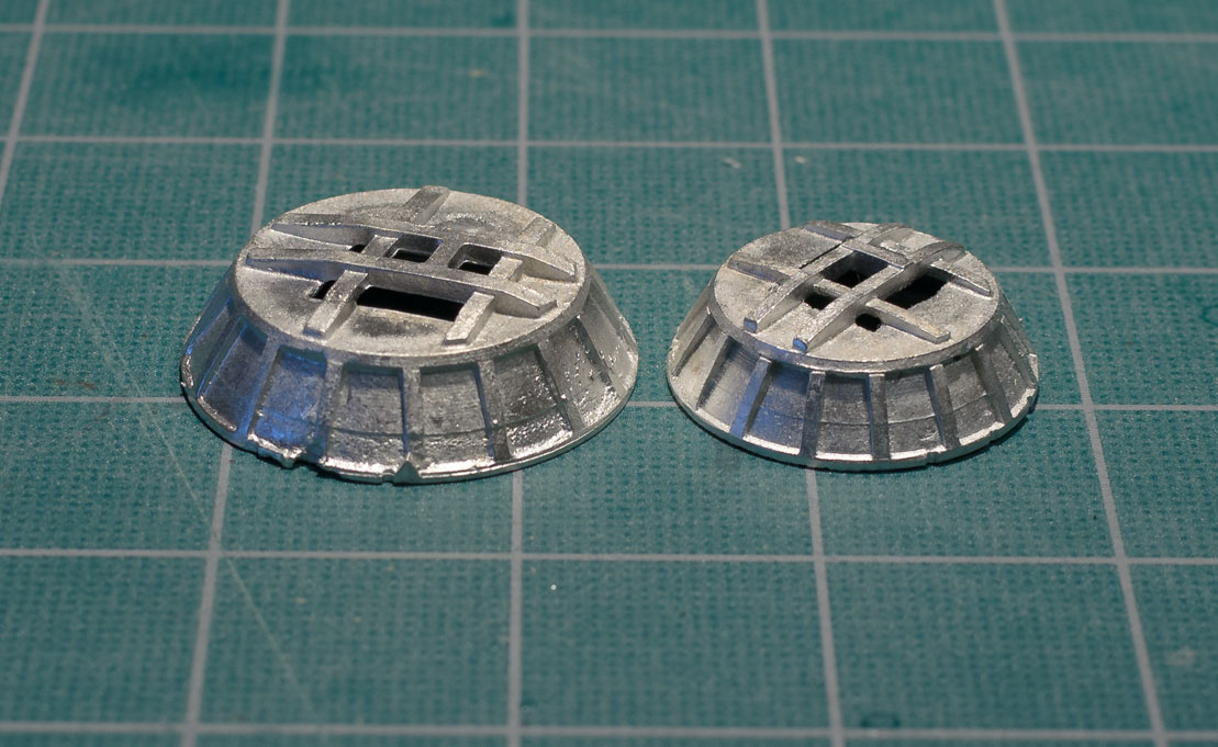
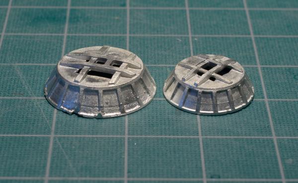
Looking at other MS Mayflower logs it appears that some of their kits supplied "Tops" made from wood. Here are mine which are made from Britannia metal. I definitely won't be using them.
-
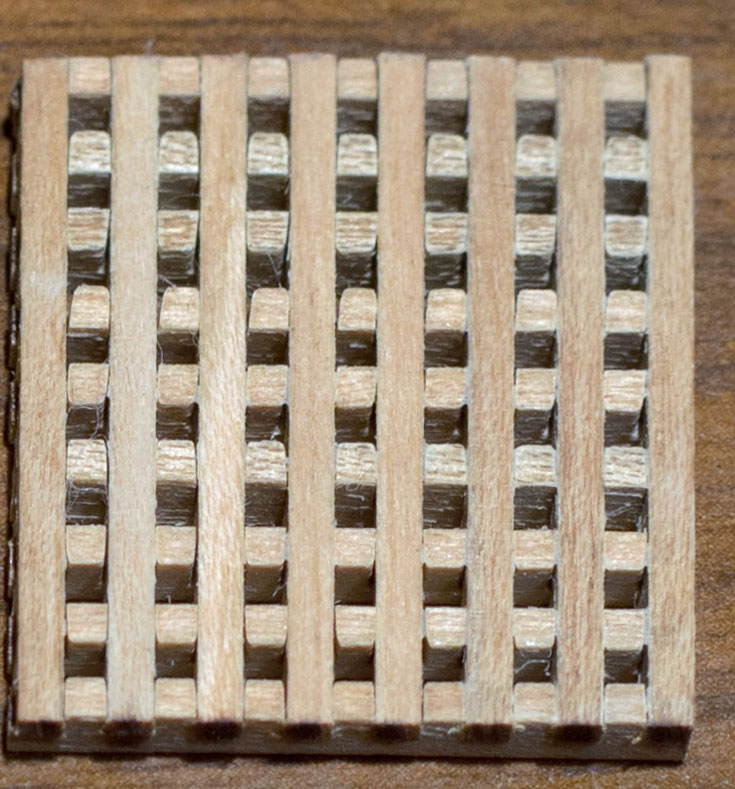
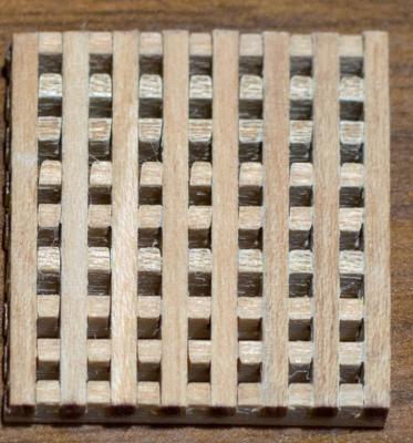
Don,Thomas and Jim, thank you for the compliments! Since my last post I have bought some hand and power tools to facilitate the scratch building of the remaining boxwood parts. Some I can make by hand others would prove too difficult. I would have used the kit supplied gratings if they were closer to scale and better quality. Unfortunately, they are not. I have seen the ones from the Brig Syren kit and they are definitely better. Since I plan on building from plans on future builds this should prove to be money well spent. Updates coming soon! Mayflower kit gratings
-
Get well soon Adam! I forgot to mention a while back that the Mayflower kit I got has Britannia Crow's nests. Yours look like they are wood. I will have to find a way to scratch them. Dave's method looks interesting.
-
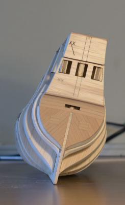
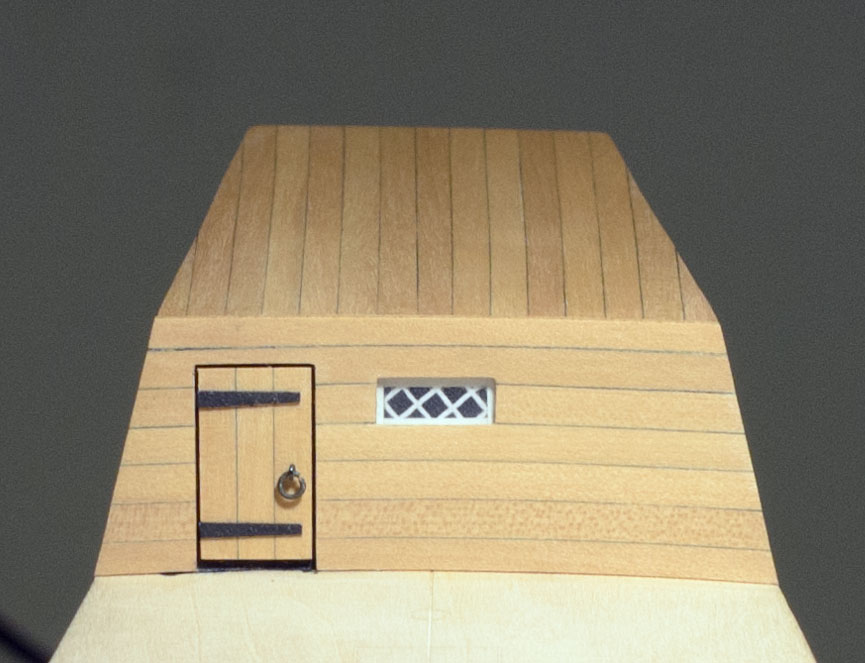
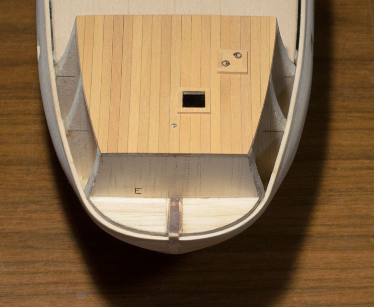
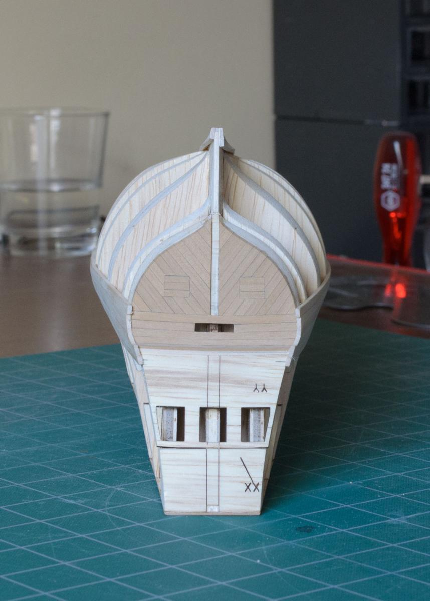
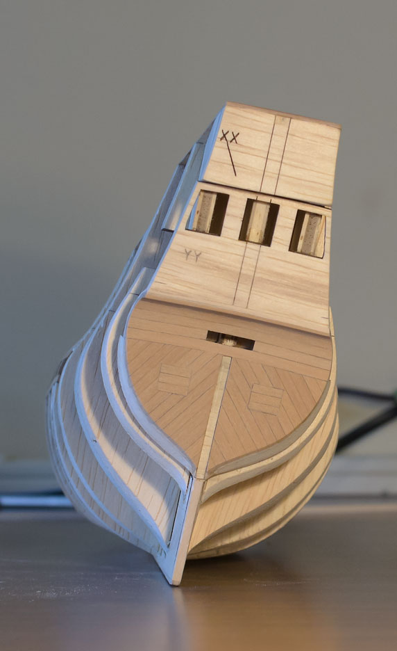
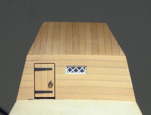
● Poop Bulkhead: A few things have made me rethink my approach to the remaining deck planking. The boxwood strips I received vary in thickness between .031"-.050". I think it would be difficult to sand the planks flat without damaging the coamings that are supposed to be glued to the main deck beforehand. Also, the kit supplied gratings do not have a tight fit when assembled and the holes are too large according to the plans. I'm working on a solution for both and will post the results hopefully soon. Meanwhile here is a photo of the Poop Bulkhead. I made a photocopy of the diamond pattern shown in the manual and used the kit supplied 1/16" white tape around the edge, with half its width showing. I left some room for the planking to run under the door as well.
-
Ditto! Mike
-
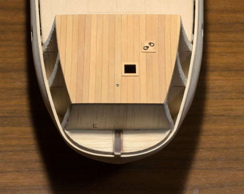
Turns out I made the two hatches the wrong size. The forecastle false deck has squares marked on it for the placement of these hatches. Instead of adding the 1/16" square strips outside of these markings I placed them inside. My thinking was that the markings represented the overall size. Wrong! Chuck's watchful eye caught the mistake. Before and after


-
● Forecastle Deck: I started the deck planking today using a #2b pencil to simulate the tarred seams. All of the deck planking will be done using boxwood. I applied a coat of Wipe-On Poly to bring out the color.

-
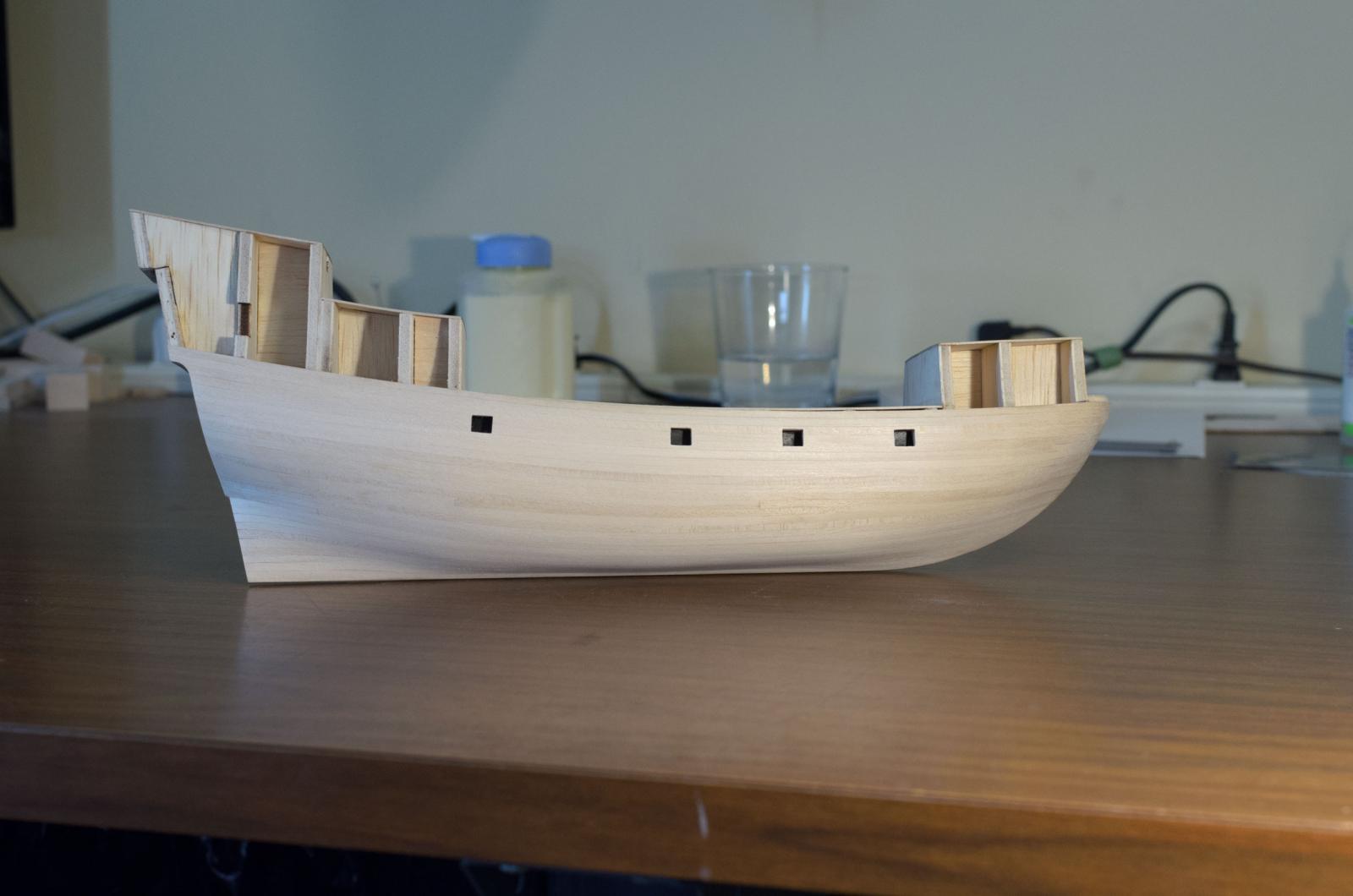
Thanks everyone for your comments and likes. When I was building airplanes, due to the filler being applied over silkspan, it was common practice to leave some filler the surface since it was not a good idea to sand through the silkspan. I started with the same approach as you can see from the previous post. I later realized that since the primer was applied directly to the wood that I could sand the hull a lot more to achieve a smooth contour while using the primer as an indicator of high and low spots. At first I was afraid of sanding through the wood, especially at the bow and stern, but there was plenty of material and no need to worry.

-
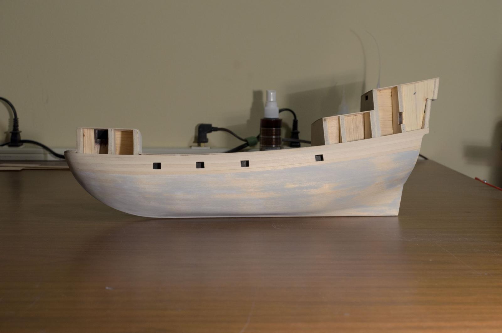
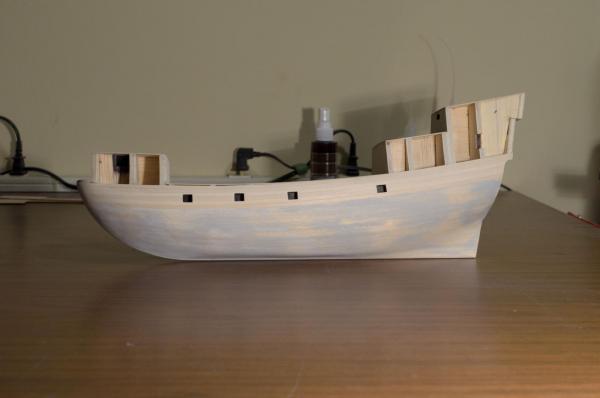
After completing the first layer planking I used some Elmers wood filler to fill small cracks and then applied a coat of primer as a color indicator for final sanding of the hull. At first I tried using the Model Master Acrylic White Primer #4622 but it wasn't opaque enough so I switched to their gray #4680.
-
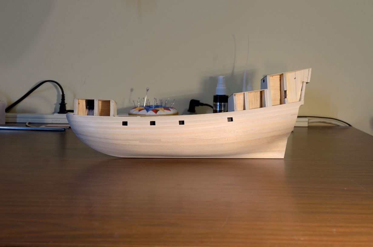
While writing my last post I was contemplating the idea of going to a second layer planking below the lower whales using boxwood and leaving it a natural wood color. I have decided against this and will simply paint the first layer planking in that area white (tallow).
-
The first layer hull planking is completed on one side with 2 more planks remaining on the other. I was hoping to finish both sides before my leaving on a week's vacation but rushing things is not an option. The completed side has been sanded with 120 grit to within 90% of where I want it. I still need to taper the planking at the stern to 1/8" where it meets the sternpost. Right now it's 1/16" too wide overall. I have to say that the experience so far has been somewhat of an eye opener. I was hoping that my planking the Longboat would have made things a lot easier, but new challenges were presented. The biggest challenge was having to plank a more rounded bow using 1/16" x 1/8" basswood strips. If not careful, this wood is sure to crease, splinter, crush or lose an edge. Although it was too late to turn back at the time, Chuck mentioned that instead of using 1/8" planks in the lower hull I could have used 5/32" planks tapered to 1/8" near bulkhead "0". This would have avoided the use of stealers altogether.

-
Ryan- Thanks! I'm really glad that you enjoyed the read also. I'm still waiting for a display case. The plexi box that was ordered from Cases For Collectibles www.casesforcollectibles.com was drop shipped to Bluejacket who will make the base. The wood is unstained cherry that I will finish myself. Unfortunately, I don't have a table saw though it is definitely on my wish list. Mike
-
John- Thanks for the kind words. Overall, I had a great time building the Longboat. There were times that I thought I had taken on too much for my first project and wanted to quit. I am glad that I didn't. Chuck and Bob f. Were a great help when I needed it. I suggest that you check out both logs before you start the project. If I can be of any help at all don't hesitate to let me know. Good luck! Mike
-
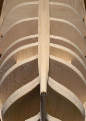
● First planking layer (part 2): Before adding the garboard planks I did as Chuck advised and thinned the rabbet down to 1/16" in the area where the stern post will go. The width across the rabbet is too wide where the planks twist and some additional sanding is needed. The planks will be sanded down gradually to around 1/32" to blend in where the stern post will be located.

-
Chuck- Thanks for the explanation. I will follow your advice. I was wondering why the hulls first planking layer was being done in 1/16" and not 1/32". Now I know.
-
I'm about to start the lower hull starting with the garboard plank. I'm not clear as to the thickness of this plank where it meets the rabbet. Since the rabbet is already 3/32" if the garboard plank remains at 1/16" then the overall thickness at the stern once both sides are completed will be 7/32" . Is this correct? Advice needed. Thanks! Mike
-
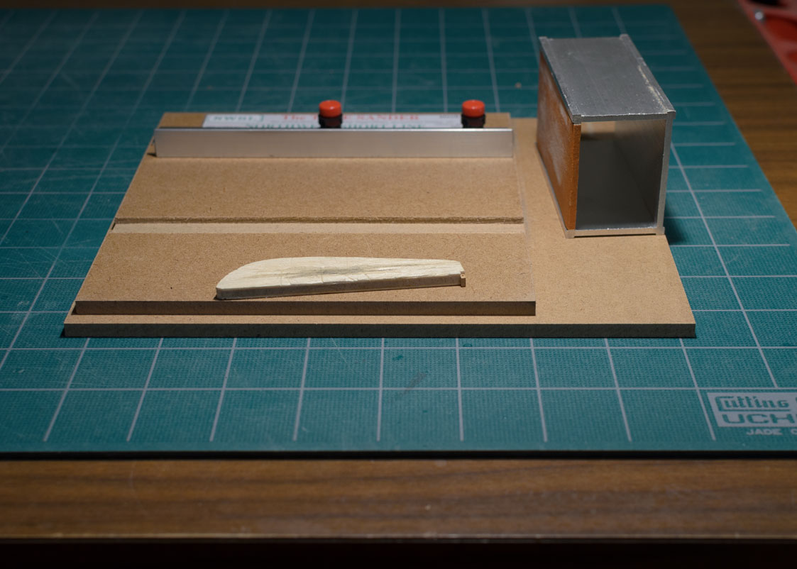
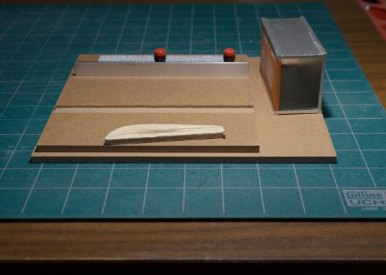
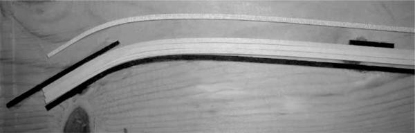
Divarty- I did some plank bending for the first 6 planks, no spiling. I will pre-spile the remaining planks using the kit supplied spiling guide as shown in the photo below. Brian- The scale is 5/32"
-
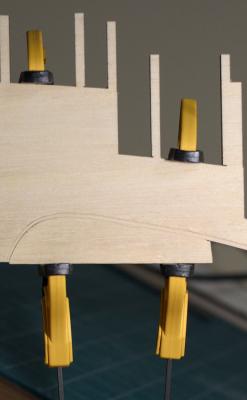
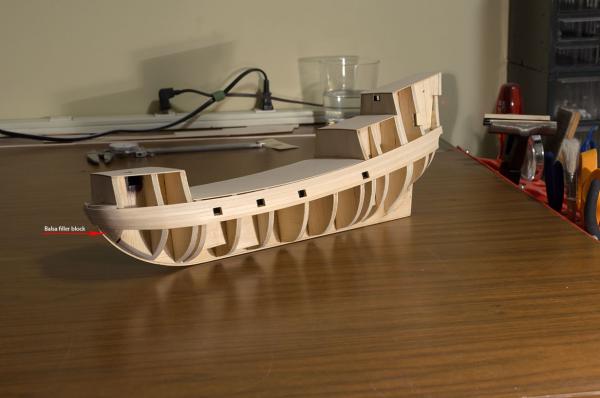
● First planking layer (part 1): 6 Planks are now in place and the gun ports are shaped. The individual planks were made from one continuous length. I used scrap laser cut sheet to create the shape for the sharp curve of the bow. I also added a balsa filler block to help when bending the plank around the bow. Before shaping the gun ports I sanded the planking with 180 grit, being very careful not to sand too close to the top edge of the initial plank or too close to the bottom edge of the last plank. My reasoning was that since additional planks would be added above and below I would leave these 2 planks at full thickness to be sanded later after all the planks are in.
-
Howlingmine, Here is a good place to start. It describes "fairing" the hull. Hope this helps. http://modelshipworldforum.com/resources/Framing_and_Planking/plankingprojectbeginners.pdf
-
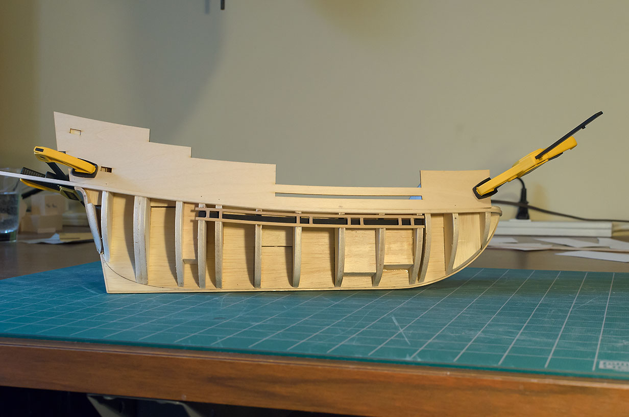
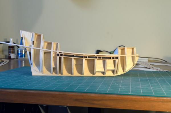
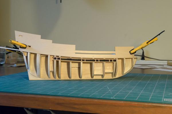
Marking the initial plank position with the bulwark template gave me a better idea of where the upper plank runs would be located. Some additional fairing of the hull was needed in order to get the planks running without dips and rises. Once one side of the hull was faired I made bulkhead profile templates from card stock. Holding the card templates up against a window I was able to trace the profiles onto the other side of the card stock. I used these tracings to match the bulkhead profiles from the faired side. Once both sides were symmetrical I checked the plank run once more to confirmed that all was good for attaching the 2 initial planks. ● Setting Initial planks: The bulwark template was used to mark the bulkheads for the location of the initial planks before they were glued into place. For these 2 planks I found it easier to form its shape by soaking in water for 5 minutes and clamping them to the hull. I used a hair dryer on its high setting to dry them. The photos below show the plank run along the bulwark template and then with the template removed.
-
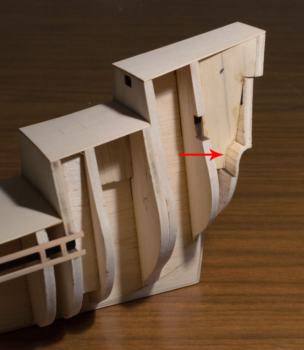
● Planking the Counter: After test fitting the first layer of planking using a 1/8" x 1/6" basswood strip I could see that it was too thin and would not allow the second layer to sit flush with bulkhead "ZZ". The fix was to place a 1/32" balsa shim below the first layer of planking. The shims were glued to the stern frames that were added earlier. The second layer was done in boxwood.