


Beef Wellington
-
Posts
2,245 -
Joined
-
Last visited
Reputation Activity
-

 Beef Wellington got a reaction from BenD in HMS Jason by Beef Wellington - Caldercraft - 1:64 - Artois-class frigate modified from HMS Diana 1794
@Pat - I tried using a very fine sanding stick after coat of primer had been sprayed on. This worked in some cases, but less so in others, and not at all in all those hard to reach corners. I've never seen many samples of 3D printing to compare to so I may be being a little unfair, and of course it comes down to the materials supplied. I ordered the "Smoothest Fine Detail' option which was the 'best' finish of those available. Its odd as one side is almost perfect, the other much rougher...https://www.shapeways.com/product/9VPR7D8CW/1-64-lower-capstan-18th-and-19th-century?optionId=64749325. I suspect other materials offered by other suppliers could give better results.
Taking stock:
Not too much time in the shipyard this weekend, trying to get the garden ready for winter. The shipyard did however get a bit of a spring cleaning as I was getting a little bit tired of working in a 2"x2" square on my cutting mat despite working on a pretty large table. A few overall shots of where things stand as its been a while. Now the channels are glued, the chainplate locations could be drilled as well as the emergency rigging eyebolt positions. The scuppers have also been completed. The positioning of all of these things requires quite a bit of planning and luckily I didn't encounter any problems with the airing ports. (I seem to recall leaving off the foremost one because it is very tightly positioned between preventer links and would have been impossible to locate correctly and likely resulted in a necessary compromise with the chain alignments.
Nearly all the parts for the upper gun deck have been completed an I'm still following the mantra of not gluing something into place until it absolutely needs to progress.
Syren rope will be used, and I would welcome peoples' opinions on which size to use for the breech rope. Picked two sizes that seemed most appropriate, left is 0.025"/0.63mm, the right is 0.35"/0.88mm. Even though I'm sure it exists, I can't find info on what regulation would be - and even if I did, the carriages and barrels are best efforts at matching scale and undoubtedly not spot on, so the right "look" is probably more important. Upon consideration, I think I'm leaning toward the smaller size, but again would appreciate input...
-
 Beef Wellington reacted to rafine in Prince de Neufchatel by rafine - FINISHED - Model Shipways - 1:64
I've now done first rigging on the lower main mast. This included the burton pendants and shrouds and the main stay. Before doing these, I added cleats and eyebolts to the masthead and trestletree-crosstree assembly, as shown on the Smithsonian drawings.
After finishing the shrouds, I added sheer poles.The stay is double and set up to tackles that are hooked to deck eyebolts forward of the fore mast. Lastly, I lashed blocks for the boom topping lifts and the gaff peak halyard to the mast head.
Next, I will repeat this process for the lower fore mast.
Bob
-
Beef Wellington reacted to rafine in Prince de Neufchatel by rafine - FINISHED - Model Shipways - 1:64
Finally, something new to report. After getting the rigging plans and data, I decided to start with the bowsprit assembly and rigging. This really wouldn't have been my usual order of doing things, but I just felt like doing it.
I began by making the bowsprit, jibboom and flying jibboom, the spritsail yard, the cap and the dolphin striker. I assembled these after shaping and filing shoulders, where needed, and painting the appropriate areas black. Before mounting, I added cleats and eyebolts as shown, and then added the deadeyes for the bobstay, shrouds and forestay and blocks for the spritsail yard braces and lifts. I then mounted the assembly.
I began the rigging with the gammoning and then did the bobstay and shrouds. After those, I did the martingales and guys.The martingales reeve through hoes in the the dolphin striker, then through eyebolts on the bowsprit, then through fairleads at the bow and to the bow pinrail. The guys lead through eyebolts on the spritsail yard and then to tackles hooked to eyebolts on the forward side of the catheads. I also added the spritsail yard lifts, which also run back to the forward pinrail. There is still considerable rigging left to do in this area when the various stays are run from the foremast.
Bob
-
Beef Wellington reacted to channell in HMS Jason by Beef Wellington - Caldercraft - 1:64 - Artois-class frigate modified from HMS Diana 1794
I'm not saying much but I'm still following along with great interest, Jason. Truly an inspirational job so far; I just love how clean, sharp and exact everything is.
-
Beef Wellington reacted to jwvolz in HMS Jason by Beef Wellington - Caldercraft - 1:64 - Artois-class frigate modified from HMS Diana 1794
Very nice work Jason!
-
Beef Wellington reacted to Old Collingwood in HMS Jason by Beef Wellington - Caldercraft - 1:64 - Artois-class frigate modified from HMS Diana 1794
Lovely work as usual jason - very high standard, such an inspirational place to visit is Vic, you can almost feel the spirits of Nelsons crew.
OC.
-
Beef Wellington reacted to BANYAN in HMS Jason by Beef Wellington - Caldercraft - 1:64 - Artois-class frigate modified from HMS Diana 1794
Thanks Jason, the capstan turned out great. A mate drew up the one I needed in a #D programme and we have also just had it printed at shapeways. I think we used ultra high definition plastic. I am just assembling my Vampire printed with the same stuff and it gave nice detail - just a cow to clean. What did you use?
cheers
Pat
-
Beef Wellington reacted to jwvolz in HMS Cruiser by Thunder - FINISHED - Caldercraft - 1:64 Scale
Good luck with your build. I'm building the kit now and it's been quite enjoyable. I've made some modifications along the way as well to try to get a more historic rendering.
I'll be following along!
-
Beef Wellington reacted to Kevin in HMS Diana by Shipyard sid - Caldercraft - 1/64 scale
Sid good afternoon, the Dianna will be my next build, after The Vic is completed, LOL i will still be a long way behind you, but will learn from your progress
-
Beef Wellington reacted to Shipyard sid in HMS Diana by Shipyard sid - Caldercraft - 1/64 scale
Greetings all
Thanks for all your comments and likes. I have sorted the run of the wale out, hopefully, and then moved on to the port side to start cutting out the gunports, but I got a bit cheesed off with them. So I have returned to the starboard side and started fitting the planking above the wale. Things have gone pretty well and I am happy with my progress, apart from the run of the planks above the ports which are not as horizontal as they should be, so I will see how the planking will look later in the build, as I did not intend to paint it. I think I have gone as far as I should go with the planking, and will return to the gunports on the port side and then plank up the same as the starboard. I have posted a few photos and as I said I am pretty happy with it. The gun ports still need tidying up especially the five with lids.
Anyway that’s me for now, wish I was planking down the hull. Thanks a lot DAVID
-
 Beef Wellington got a reaction from Shipyard sid in HMS Jason by Beef Wellington - Caldercraft - 1:64 - Artois-class frigate modified from HMS Diana 1794
Sjors - maybe these photos will help you make up your mind The planking is not as beautiful as I think you think because of the different woods used, copper was always the plan.
Believe I reached a point to deliver a verdict on the Amati plates and share some progress now that copper has met boxwood. I know that there seem to be many diverse opinions on coppering, and it does present its own uniquw challenges. Its also amazing how many varied diagrams there are of copper plate layouts. In the end, I probably ended up somewhere between what is shown in the AOTS Pandora book and TFFM book 2.
So, some thoughts on the Caldercraft:Amati copper plate matchup. First off, I cannot believe how much more fun it is to work with the Amati plates vs my experience with the Caldercraft plates (which do still give a nice result).
Because the plates come in sheets, its possible to apply in some cases in multiple plates at a time. This is a real bonus when its necessary to shape some which otherwise would leave a tiny sliver to be attached. This results in less wastage..at least so far. The thin profile of the PE plated I think attaches much more easily (in my experience) using the Admiralty Pro thick CA glue. This also allows any needed overlaps to be achieved easily without having to hammer out the distinct nail head profiles on the CC plates On to the photos and little bit of the method I've found works well for me. I started working on the stern as this will likely be the most challenging due to the hull shape.
I'm not sure what these are called, but determining the flow of the plates where they need to fan out is the first challenge. Because the plates don't bend and can't be spiled, the problem is a little more intractable. I found that by using a small sheet 2 tiles wide to find the natural lines of how the plates lie well on the hull was the simplest method, it just takes time and fiddling....
Once the lined had been figured out, household painters tape helped me keep the lines straight at these transition points (I go through a lot of tape)
From above (the view as I work), the lines of the plates does appear a little erratic...
...however, the appearance from normal angles is much more acceptable
-
 Beef Wellington got a reaction from Jorge Diaz O in HMS Jason by Beef Wellington - Caldercraft - 1:64 - Artois-class frigate modified from HMS Diana 1794
Thanks everyone as always for continued interest....
Jim - not going to be able to put canon rigging off much longer....ugghh
The area around and immediately aft of the pumps is really quite congested and requires some planning. The main jeer and topsail sheet bitts were scratched, parts from the kit look a little oversize to my eye. Pillars were made square in section after studying as many pictures as I could find, these seem to be a mix between square and round, but I don't think my turning skills are up to making round ones. Side blocks and fake sheaves were also added.
For the aftermost stanchions, I followed the AOTS diagrams which shows these to be of smaller dimension. All of these items will require some final finishing. The capstan step was cut out of a single piece of 2mm boxwood and 'joints' faked by scoring with a knife and filling with pencil lead. This took a while with just hand tools and I couldn't help but think of a toilet seat from the end result! These details will be visible but obscured so forcing myself not to be too fussy. The base of the capstan itself as sanded back to the pawl rim which sits in the hole in the capstan step. (This requires a lot more finishing to get the surface to be acceptable)
Pictures are hopefully self explanatory. I've shaped some box for the elm tree pump shafts and I've placed an offcut just to get a sense for positioning....
And to mystery that's been puzzling me for a while (and Rob alludes to in his Ethalion log), how does the placement of the pump brakes reconcile in the this workspace in such close proximity to the capstan and companion?
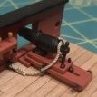
I seem to recall reading 'somewhere' that some stanchions were removeable which would explain the location around the capstan - once both sets were removed this would make this workable. In later ships, these seem to have been replaced by hinged iron columns which makes a lot of sense. if anyone could corroborate that would be much appreciated! Lastly, given the pump brakes also extend to this area, these would really be a permanent accident waiting to happen at the foot of the ladder to the quarterdeck which must have received quite a bit of use. I can't find any reference to this, bit I have to suspect that pump brakes were removeable, and unshipped when not in use. On the Artios class, there is a set forward, and 2 sets aft - in normal seagoing routine I would speculate that not all banks would have been needed, but could easily have been placed in the event or expectation of an emergency. The last photo below from Victory seems to show exactly this, and it also makes the square section joining each brake much more functional. Again, if anyone can point me to sources would be much appreciated!
-
Beef Wellington reacted to RGL in SMS Seydlitz by Canute, Cog, Stein Gildberg & RGL - FINISHED - Hobbyboss - 1/350 - PLASTIC
There is nothing below the waterline when it comes to details. There is also no strakes along the bow which are on the real thing.
So some marskung and some very thin tape soles that quickly. I need to get some more rattle can spray to finish coverage on the Lower hull, then I can scribe in some panels.
I also added some riveted panels to the rudders and above the cannons that run along the edge of the hull.
-
 Beef Wellington got a reaction from ccoyle in HMS Cruiser by Thunder - FINISHED - Caldercraft - 1:64 Scale
I believe the "Cruizer" kits are similar (if not identical in many regards) to the Snake kit offering of which there are quite a few comprehensive build logs on this site. The only real major differences being the addition of platforms on Snake, use of carronades vs canons and the additional mast. I believe both of the kits are earlier Caldercraft releases, so I think you may find them a little less refined than later offerings (certainly fewer detailed PE parts). Good luck getting started.
-
Beef Wellington reacted to Thunder in HMS Cruiser by Thunder - FINISHED - Caldercraft - 1:64 Scale
Hi, as requested photographs of the parts. I have realised that I have probably had this kit for probably 15 years. My wife brought it me after visiting the companies premises and having a tour. At the time Mars had just come out and they were developing Pickle.
A few of the parts are not shown as the build has already started.
-
Beef Wellington reacted to herask in 74-gun ship by Gaetan Bordeleau - 1:24
Gaetan, the second photo can easily replace the one on the cover of Ancre's 74-gun ship publication. found my new desktop image...
-
Beef Wellington reacted to Gaetan Bordeleau in 74-gun ship by Gaetan Bordeleau - 1:24
USING A FLASH OR NOT?
Last week, a man, in an exhibition, was saying that he was always using a flash in manual mode, never in TTL (true the lens). Many years ago, it was true. Todays flash are much more performing.
Here is another common belief : a studio flash is much more performing than a flash on a camera. With the development of the electronic technology; you can buy a flash which fits on the camera hot shoe and it can perform in TTL as good as in manual. This week, I got a new on camera flash and I am very please by his performance.
On the last 2 photos, untouched, show the result of this morning test : The first one : with a flash in TTL mode, 100% automatic. The last one : no flash, neon lighting. The color are not as much appealing!
-
 Beef Wellington got a reaction from Old Collingwood in HMS Jason by Beef Wellington - Caldercraft - 1:64 - Artois-class frigate modified from HMS Diana 1794
Pat - the capstan is the 3D printed one I had previously ordered. I had ordered the 'best quality' I could from Shapeways as well as a few other things, but in my opinion the quality of finish won't fly for items that are openly visible. However, I can live with these for items that are mostly obscured (stove and lower capstan). I'll be scratching my own quarterdeck capstan.
Paul - thanks for confirming.
-
Beef Wellington got a reaction from BenD in HMS Jason by Beef Wellington - Caldercraft - 1:64 - Artois-class frigate modified from HMS Diana 1794
Thanks everyone as always for continued interest....
Jim - not going to be able to put canon rigging off much longer....ugghh
The area around and immediately aft of the pumps is really quite congested and requires some planning. The main jeer and topsail sheet bitts were scratched, parts from the kit look a little oversize to my eye. Pillars were made square in section after studying as many pictures as I could find, these seem to be a mix between square and round, but I don't think my turning skills are up to making round ones. Side blocks and fake sheaves were also added.
For the aftermost stanchions, I followed the AOTS diagrams which shows these to be of smaller dimension. All of these items will require some final finishing. The capstan step was cut out of a single piece of 2mm boxwood and 'joints' faked by scoring with a knife and filling with pencil lead. This took a while with just hand tools and I couldn't help but think of a toilet seat from the end result! These details will be visible but obscured so forcing myself not to be too fussy. The base of the capstan itself as sanded back to the pawl rim which sits in the hole in the capstan step. (This requires a lot more finishing to get the surface to be acceptable)
Pictures are hopefully self explanatory. I've shaped some box for the elm tree pump shafts and I've placed an offcut just to get a sense for positioning....
And to mystery that's been puzzling me for a while (and Rob alludes to in his Ethalion log), how does the placement of the pump brakes reconcile in the this workspace in such close proximity to the capstan and companion?
I seem to recall reading 'somewhere' that some stanchions were removeable which would explain the location around the capstan - once both sets were removed this would make this workable. In later ships, these seem to have been replaced by hinged iron columns which makes a lot of sense. if anyone could corroborate that would be much appreciated! Lastly, given the pump brakes also extend to this area, these would really be a permanent accident waiting to happen at the foot of the ladder to the quarterdeck which must have received quite a bit of use. I can't find any reference to this, bit I have to suspect that pump brakes were removeable, and unshipped when not in use. On the Artios class, there is a set forward, and 2 sets aft - in normal seagoing routine I would speculate that not all banks would have been needed, but could easily have been placed in the event or expectation of an emergency. The last photo below from Victory seems to show exactly this, and it also makes the square section joining each brake much more functional. Again, if anyone can point me to sources would be much appreciated!
-
 Beef Wellington got a reaction from Blue Ensign in HMS Jason by Beef Wellington - Caldercraft - 1:64 - Artois-class frigate modified from HMS Diana 1794
Thanks everyone as always for continued interest....
Jim - not going to be able to put canon rigging off much longer....ugghh
The area around and immediately aft of the pumps is really quite congested and requires some planning. The main jeer and topsail sheet bitts were scratched, parts from the kit look a little oversize to my eye. Pillars were made square in section after studying as many pictures as I could find, these seem to be a mix between square and round, but I don't think my turning skills are up to making round ones. Side blocks and fake sheaves were also added.
For the aftermost stanchions, I followed the AOTS diagrams which shows these to be of smaller dimension. All of these items will require some final finishing. The capstan step was cut out of a single piece of 2mm boxwood and 'joints' faked by scoring with a knife and filling with pencil lead. This took a while with just hand tools and I couldn't help but think of a toilet seat from the end result! These details will be visible but obscured so forcing myself not to be too fussy. The base of the capstan itself as sanded back to the pawl rim which sits in the hole in the capstan step. (This requires a lot more finishing to get the surface to be acceptable)
Pictures are hopefully self explanatory. I've shaped some box for the elm tree pump shafts and I've placed an offcut just to get a sense for positioning....
And to mystery that's been puzzling me for a while (and Rob alludes to in his Ethalion log), how does the placement of the pump brakes reconcile in the this workspace in such close proximity to the capstan and companion?
I seem to recall reading 'somewhere' that some stanchions were removeable which would explain the location around the capstan - once both sets were removed this would make this workable. In later ships, these seem to have been replaced by hinged iron columns which makes a lot of sense. if anyone could corroborate that would be much appreciated! Lastly, given the pump brakes also extend to this area, these would really be a permanent accident waiting to happen at the foot of the ladder to the quarterdeck which must have received quite a bit of use. I can't find any reference to this, bit I have to suspect that pump brakes were removeable, and unshipped when not in use. On the Artios class, there is a set forward, and 2 sets aft - in normal seagoing routine I would speculate that not all banks would have been needed, but could easily have been placed in the event or expectation of an emergency. The last photo below from Victory seems to show exactly this, and it also makes the square section joining each brake much more functional. Again, if anyone can point me to sources would be much appreciated!
-
Beef Wellington got a reaction from Jorge Diaz O in HMS Jason by Beef Wellington - Caldercraft - 1:64 - Artois-class frigate modified from HMS Diana 1794
Cheers Gents, appreciate the support, comments and likes...
Welcome aboard Ian 🙂
A rather dreary rainy day precluded any other activities so as able get a decent amount of time in. Spent most of the day completing the cannon carriages, these really are incredibly time consuming and seemingly never ending, but can now report are complete. I did decide to cheat a little on those carriages that will be mostly obscured away from the waist. Rather than continuing to use the pins to simulate bolts which are incredibly fiddly, the carriage bolts were simulated using a fine tip black pen and then touch of dark iron paint to tone it down. Pins have been used on all the carriages that will mount in or immediately about the waist. The macro photo below shows the 'real' bolts in the foreground and the 'cheat' in the rear. At real life viewing distance these are difficult to tell apart if you didn't know - the difference really being the lack of about 8hrs of cursing.
Experimentation with the cap squares and royal cyphers next...
-
Beef Wellington got a reaction from BenD in HMS Jason by Beef Wellington - Caldercraft - 1:64 - Artois-class frigate modified from HMS Diana 1794
Well I'm back on track at least after the destruction, painful, but glad its behind me....
The bigger channels are completed now and ready to be glued into position, I'll be leaving the attachment of the smaller channels for the topmast backstays until after the quarterdeck is glued into position. A final finish has been put on the hull, which means that I can now start to put some of the detailing in place in conjunction with fitting the chains. There seem to be a number of position where space will be tight, so fingers crossed previous planning works out.
For reference, I've marked out the expected position of the quarterdeck ports (and the previous template position with a dotted line) but will not be cutting these out until the quarterdeck is in place. This shows them in relation to the actual position of the deadeyes, with a bit of imagination (I used string and a mock up of the masts) its clear that the previous port locations would be obscured (the second and third from the stern are the tricky ones). Even though not obscured, the 4th port from the rear was moved so the port separation is equalized as much as possible. My advice to anyone modifying the kit (or even building from the box) is to leave the positioning and cutting out of any these quarterdeck ports until after the final position of the deadeyes is known.
Unfortunately, the PE hinges supplied in the kit are too small and dimension, and too bulky, for the sizes of the sweep/airing ports estimated from the AOTS plans. Luckily I had purchased a PE set for (I think!) the HMS Grenado way back and it contains some useable hinges. These smaller PE sets are pretty reasonably priced, and I've found can be handy to have as they contain a multitude of potentially useful fittings (hooks etc.) which can be used to supplement the older 'bare bones' CC kit PE sets.
These were given a few coats of paint to bulk them up a bit as although they are theoretically the same scale, the ports on Grenado are of smaller dimension. Placement on the airing ports proved a little challenging due to the elevated profile of the black-strake that runs through these.
-
Beef Wellington got a reaction from BenD in HMS Jason by Beef Wellington - Caldercraft - 1:64 - Artois-class frigate modified from HMS Diana 1794
Destruction...
Need to jump in and get going with the destruction to correct the gun ports so this doesn't derail me. There will be 3 or 4 ports per side that need to be moved, so doing individually would not make sense. Fortuitously, I had used a strip of 6mm wide box for the uppermost strake. With one minor exception, the rough cut ports don't extend below this so replacing this one strake seems to be the way to go.
Started off on the port side using isopropyl alcohol and a sharp blade to try to pry the 1mm thick strip from the 1.5mm thick template. Although I eventually got there, its a real dogs breakfast (mess). I just couldn't get the isopropyl to penetrate where I needed it sufficiently without compromising the surrounding structures (the template is laminate strip which will de-bond as well if too much isopropyl is used). As you can see in the pictures, a couple of shards got stripped away in the process where the box strip had been edge glued and but not sufficiently softened. The isopropyl also got onto the painted surface below and marred the finish, so this will need touching up. Once replaced, filled and finished, hoping this will not be noticeable.
Before tackling the starboard side, the approach needed to be amended to allow the isopropyl to penetrate more thoroughly and evenly. Took a while, drilled a multitude of holes in the strake to be removed and then applied the isopropyl. Despite taking a while to drill, this was SO much easier and gave a MUCH cleaner result. It also allowed the glued edges to soften sufficiently to debond cleanly. Now the scary part is over, the strake can be replaced and the template ports filled before getting back to where I was with the channels....
-
 Beef Wellington got a reaction from Landlubber Mike in HMS Jason by Beef Wellington - Caldercraft - 1:64 - Artois-class frigate modified from HMS Diana 1794
Thanks for the encouragement gents, certainly helps one stay motivated.
Channels:
I realize I'm continuing to bounce around, so apologies if this is not the most sequential log. Have been continuing to work on the deck fittings, none of which are glued in place yet (posts to come), but diverted to the channels. I think it will makes sense to have the channels and chains in place before any of the cannons are finally fitted - they just seem to be too exposed to not court disaster. This seems a "damned if you do, damned if you don't" situation so any advise here would be gratefully received.
I'd share the approach to the channels in an earlier post, so luckily work was more just final finishing. I wanted to introduce the rather pleasing profile on the edge as it seems to reduce the perceived bulk of the channel noticeably to my eye. I have to say, this has been some of the most challenging 'scraper work' I've yet done. Getting clean (or as clean as I can!) edges on all of the compound curvatures, as well as dealing with scraping across end grains at the fore and aftmost faces proved a real challenge. To add to this, I realized that the batten that keeps the chains in place also needs to be profiled. I'm taking the approach of temporarily gluing the batten in place, profiling, and then will de-bond using rubbing alcohol. The thinking being that once these are shaped, it should be relatively straightforward to glue permanently once the deadeyes and chains are in position. Each one will be carefully notated so I can match them up again. I've put on a very thin coat of wipe on poly to enhance the visibility of the profiles surface and see where I am...there will definitely need to be a little fine tuning once all are done, bit hopefully this illustrates.
I'm following the NMM plans as closely as I can, which show both the initial draft with open quarterdeck, as well as the changes when the quarterdeck bulwark was built up. Not only does the position of the channels change, but the alignment of the chains. Not having had the plans earlier, I had used the kit supplied template as a foundation..... I have now reached the point in the build that every Artois class builder doing an open bulwark version seams to reach, which is the realization that the position of the quarterdeck ports need to be modified - wish I'd ordered the NMM plans sooner. The gunport openings changed when the position of the channels was changed with the addition of the built up bulwark. This will require the position of the gun ports to be corrected. How I wish that I had simply planked over the kit template rather than planking around the ports, it would have made a fix unnecessary. I'm moving on while I consider how best to do this.
-
 Beef Wellington got a reaction from chris watton in HMS Jason by Beef Wellington - Caldercraft - 1:64 - Artois-class frigate modified from HMS Diana 1794
Interim update:
Anchor chain is on finally, been putting this off but really had to get it done so I could permanently 'right-side' the model...its amazing how many configurations there are on models and there really doesn't seem to be a standard way.
Next up, as a break from the repetitious chore of the gun carriages, was to finish the pumps. I'd been overthinking how to cover the curved surface of the pump covers. In the end, 1x2mm strip was used, with one side angled - wasn't as bad as I thought. Once attached, the thickness was sanded down to try to get a more scale look. Winch bearingsfor the pumps were shaped from strip and painted 'dark iron'. Brown paint was used to simulate the leather washer for the cistern plugs. These will be a little obscured eventually, but I think these details will be visible.
Once the pumps were completed, the next logical step is to figure out how to support these at the main hatch. The kits indicates using wooden strip for this, but contemporary models show an iron bracket and this is what I' like to try to replicate as it seems more appropriate. The main part of the bracket was made using an RB models stanchion, bent to shape and with the hole enlarged with a 0.8mm drill bit to accept the winches that will eventually be installed. The height of these needs to be the same as the winch bearings so that the winch will be parallel to the deck, and they need to be parallel to the deck and over the coamings so the main hatch is not obscured - so this essentially determines the lateral placement of the pumps. I will add an additional bracket which would have been necessary for strength, and you can see a trial made up from some scrap PE to illustrate which I think will do the trick.
I found thinking this through all rather intriguing as there seem to be some obvious problems. For anyone coming from the lower deck, the ladder feads directly over the main hatch grating, and the winch brackets definitely seem to get in the way a bit here here, in addition to having to navigating the pump winches. I can't figure out for the life of me why the ladders don't lead up forward rather than aft as this would seem to be much more practical, but this orientation is clearly shown on the original plans, AOTS Diana, as well as contemporary models...if anyone knows why, please say so!
Now that the positioning of the pump winches is known, the placement of the pillars for the main topsail sheet and main jeer bitts can be determined...which will probably be the next diversion.