


Beef Wellington
-
Posts
2,245 -
Joined
-
Last visited
Reputation Activity
-

 Beef Wellington got a reaction from Landlubber Mike in HMS Jason by Beef Wellington - Caldercraft - 1:64 - Artois-class frigate modified from HMS Diana 1794
Hi Carl, this is one of those things that is very hard to capture in a photo (at least on my iPhone 'camera'). The finish does have a pleasant sheen, certainly not 'matte', it also brings a more consistent colour finish to all barrels as each one does tend to have a slightly different sheen and/or colour hue - definitely still at the 'artistic' stage rather than 'repeatable scientific process'. 🤐
-
Beef Wellington got a reaction from Landlubber Mike in HMS Jason by Beef Wellington - Caldercraft - 1:64 - Artois-class frigate modified from HMS Diana 1794
Gun Carriages:
Nothing revolutionary, prototype gun carriage has been completed after putting on some more coats of paint to the carriages. Learning experience here is to use as little paint on metal items as possible, all ring bolts and ring bolts have been chemically blackened. Cannon barrels and ring bolts have been finished with Testors clear matt lacquer to eliminate the shine still inherent to the blackened surface. The carriage bolts are model railway/railroad track pins which have a shallow domed head, these come painted black, so the head was painted with 'dark iron' before attaching. I had experimented with countersinking these on a spare, but this seemed a little over fussy, and also just using wire cut off wire but felt these looked too dainty.
Event though many of these will be obscured by the deck, I will probably build all of these as per the prototype in case glimpses can be seen through various openings. The guns that are highly visible will likely get a little more detailing but I'll decide to what extent when all of these are done.
Its a little disconcerting when I sat back a figured out what will be needed, and this is just the upper deck. Everything is at least now ready for assembly....
ringbolts - 336 blackened (7 per carriage, 4 per bulwark, 1 deck bolt) Domed pins - 168 (6 per carriage) 3mm rings - 112 (2 per carriage for breaching rope, 2 per gunport for breaching rope) 2mm rings - 28 (1 per gunport deckring)
So far 3 carriages have been built up, as the best method for construction becomes clearer, these do seem to be going together more quickly, but still not quickly 🙂
-
 Beef Wellington got a reaction from Old Collingwood in HMS Jason by Beef Wellington - Caldercraft - 1:64 - Artois-class frigate modified from HMS Diana 1794
Pat - the capstan is the 3D printed one I had previously ordered. I had ordered the 'best quality' I could from Shapeways as well as a few other things, but in my opinion the quality of finish won't fly for items that are openly visible. However, I can live with these for items that are mostly obscured (stove and lower capstan). I'll be scratching my own quarterdeck capstan.
Paul - thanks for confirming.
-
 Beef Wellington got a reaction from Jorge Diaz O in HMS Jason by Beef Wellington - Caldercraft - 1:64 - Artois-class frigate modified from HMS Diana 1794
Cheers Gents, appreciate the support, comments and likes...
Welcome aboard Ian 🙂
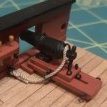
A rather dreary rainy day precluded any other activities so as able get a decent amount of time in. Spent most of the day completing the cannon carriages, these really are incredibly time consuming and seemingly never ending, but can now report are complete. I did decide to cheat a little on those carriages that will be mostly obscured away from the waist. Rather than continuing to use the pins to simulate bolts which are incredibly fiddly, the carriage bolts were simulated using a fine tip black pen and then touch of dark iron paint to tone it down. Pins have been used on all the carriages that will mount in or immediately about the waist. The macro photo below shows the 'real' bolts in the foreground and the 'cheat' in the rear. At real life viewing distance these are difficult to tell apart if you didn't know - the difference really being the lack of about 8hrs of cursing.
Experimentation with the cap squares and royal cyphers next...
-
Beef Wellington got a reaction from Jorge Diaz O in HMS Jason by Beef Wellington - Caldercraft - 1:64 - Artois-class frigate modified from HMS Diana 1794
Thanks everyone as always for continued interest....
Jim - not going to be able to put canon rigging off much longer....ugghh
The area around and immediately aft of the pumps is really quite congested and requires some planning. The main jeer and topsail sheet bitts were scratched, parts from the kit look a little oversize to my eye. Pillars were made square in section after studying as many pictures as I could find, these seem to be a mix between square and round, but I don't think my turning skills are up to making round ones. Side blocks and fake sheaves were also added.
For the aftermost stanchions, I followed the AOTS diagrams which shows these to be of smaller dimension. All of these items will require some final finishing. The capstan step was cut out of a single piece of 2mm boxwood and 'joints' faked by scoring with a knife and filling with pencil lead. This took a while with just hand tools and I couldn't help but think of a toilet seat from the end result! These details will be visible but obscured so forcing myself not to be too fussy. The base of the capstan itself as sanded back to the pawl rim which sits in the hole in the capstan step. (This requires a lot more finishing to get the surface to be acceptable)
Pictures are hopefully self explanatory. I've shaped some box for the elm tree pump shafts and I've placed an offcut just to get a sense for positioning....
And to mystery that's been puzzling me for a while (and Rob alludes to in his Ethalion log), how does the placement of the pump brakes reconcile in the this workspace in such close proximity to the capstan and companion?
I seem to recall reading 'somewhere' that some stanchions were removeable which would explain the location around the capstan - once both sets were removed this would make this workable. In later ships, these seem to have been replaced by hinged iron columns which makes a lot of sense. if anyone could corroborate that would be much appreciated! Lastly, given the pump brakes also extend to this area, these would really be a permanent accident waiting to happen at the foot of the ladder to the quarterdeck which must have received quite a bit of use. I can't find any reference to this, bit I have to suspect that pump brakes were removeable, and unshipped when not in use. On the Artios class, there is a set forward, and 2 sets aft - in normal seagoing routine I would speculate that not all banks would have been needed, but could easily have been placed in the event or expectation of an emergency. The last photo below from Victory seems to show exactly this, and it also makes the square section joining each brake much more functional. Again, if anyone can point me to sources would be much appreciated!
-
 Beef Wellington got a reaction from BenD in HMS Jason by Beef Wellington - Caldercraft - 1:64 - Artois-class frigate modified from HMS Diana 1794
Thanks everyone as always for continued interest....
Jim - not going to be able to put canon rigging off much longer....ugghh
The area around and immediately aft of the pumps is really quite congested and requires some planning. The main jeer and topsail sheet bitts were scratched, parts from the kit look a little oversize to my eye. Pillars were made square in section after studying as many pictures as I could find, these seem to be a mix between square and round, but I don't think my turning skills are up to making round ones. Side blocks and fake sheaves were also added.
For the aftermost stanchions, I followed the AOTS diagrams which shows these to be of smaller dimension. All of these items will require some final finishing. The capstan step was cut out of a single piece of 2mm boxwood and 'joints' faked by scoring with a knife and filling with pencil lead. This took a while with just hand tools and I couldn't help but think of a toilet seat from the end result! These details will be visible but obscured so forcing myself not to be too fussy. The base of the capstan itself as sanded back to the pawl rim which sits in the hole in the capstan step. (This requires a lot more finishing to get the surface to be acceptable)
Pictures are hopefully self explanatory. I've shaped some box for the elm tree pump shafts and I've placed an offcut just to get a sense for positioning....
And to mystery that's been puzzling me for a while (and Rob alludes to in his Ethalion log), how does the placement of the pump brakes reconcile in the this workspace in such close proximity to the capstan and companion?
I seem to recall reading 'somewhere' that some stanchions were removeable which would explain the location around the capstan - once both sets were removed this would make this workable. In later ships, these seem to have been replaced by hinged iron columns which makes a lot of sense. if anyone could corroborate that would be much appreciated! Lastly, given the pump brakes also extend to this area, these would really be a permanent accident waiting to happen at the foot of the ladder to the quarterdeck which must have received quite a bit of use. I can't find any reference to this, bit I have to suspect that pump brakes were removeable, and unshipped when not in use. On the Artios class, there is a set forward, and 2 sets aft - in normal seagoing routine I would speculate that not all banks would have been needed, but could easily have been placed in the event or expectation of an emergency. The last photo below from Victory seems to show exactly this, and it also makes the square section joining each brake much more functional. Again, if anyone can point me to sources would be much appreciated!
-
 Beef Wellington got a reaction from chris watton in HMS Jason by Beef Wellington - Caldercraft - 1:64 - Artois-class frigate modified from HMS Diana 1794
Cheers Gents, appreciate the support, comments and likes...
Welcome aboard Ian 🙂
A rather dreary rainy day precluded any other activities so as able get a decent amount of time in. Spent most of the day completing the cannon carriages, these really are incredibly time consuming and seemingly never ending, but can now report are complete. I did decide to cheat a little on those carriages that will be mostly obscured away from the waist. Rather than continuing to use the pins to simulate bolts which are incredibly fiddly, the carriage bolts were simulated using a fine tip black pen and then touch of dark iron paint to tone it down. Pins have been used on all the carriages that will mount in or immediately about the waist. The macro photo below shows the 'real' bolts in the foreground and the 'cheat' in the rear. At real life viewing distance these are difficult to tell apart if you didn't know - the difference really being the lack of about 8hrs of cursing.
Experimentation with the cap squares and royal cyphers next...
-
 Beef Wellington reacted to paulsutcliffe in HMS Jason by Beef Wellington - Caldercraft - 1:64 - Artois-class frigate modified from HMS Diana 1794
Nice work Jason, I think you are correct that all the stanchions and brakes were removeable when the capstan was in use
Regards
Paul
-
-
Beef Wellington reacted to BANYAN in HMS Jason by Beef Wellington - Caldercraft - 1:64 - Artois-class frigate modified from HMS Diana 1794
Some very nice detail in that work Jason. Did you carve/make your capstan from scratch as the detail of the pawls etc is very well defined and consistent.
cheers
Pat
-
Beef Wellington reacted to cog in HMS Jason by Beef Wellington - Caldercraft - 1:64 - Artois-class frigate modified from HMS Diana 1794
Awesome, Jason. Especially the last picture ... so life like Love the details on the carriages, and the capstan. Metal parts really stand out
Cheers
-
Beef Wellington reacted to wefalck in How to tie a rope to handrail
Yes, #2 and 4# represent what I meant by doubling.
Adding more turns around the bar will not necessarily add more safety, but it depends really on the specific geometrical situation and the amount of pull on the rope. The seaman will do instinctively the right thing, e.g. if one turn slips, he would add one more, etc. It is difficult to decide this on a theoretical basis.
In general, 'less is more', meaning that one would use the least amount of turns and knots possible. Any additional turns and knots makes it more difficult to cast loose a rope in an emergency. It is a sign of poor understanding of seamanship to add unnecessary amount of knots (as many landlubbers have a tendency to do)
-
Beef Wellington reacted to Ferit in How to tie a rope to handrail
Single and doubling...
Please let me know your suggestion if the drawings are correct...
(Maybe for #3 and #4 to add around one winding before the clove hitch.)
-
Beef Wellington reacted to AON in HMS Bellerophon 1786 by AON – scale 1:64 – 74-gun 3rd Rate Man of War - Arrogant-Class
Simple.
I am the Admiral on my ship.
However, please do not disturb Her Majesty with this info.
-
Beef Wellington reacted to Gahm in HM Cutter Cheerful 1806 by Blue Ensign - FINISHED - Syren Ship Model Company - 1:48 scale
You are now into the fun stuff, and you do it extremely well 😉
Thomas
-
Beef Wellington reacted to Vicnelson in HMS Agamemnon by Vicnelson - Caldercraft - 1:64
18 pounders ready for running out tackle etc; awaiting some bits and bobs (blocks, rings and hooks for gun tackle) from Cornwall Boats.
Dry Fitting channels; I'll finish gun ports lids before getting the glue out for these.
Gunport lids fitted to port side; just to fit gunport ropes and I can attach port side channels; then onto starboard side. Fitting out the upper gun deck beckons - might have that done by Christmas... if I get the tackle I've ordered Running about 6 weeks behind my initial build schedule.
-
Beef Wellington reacted to Koppalakki in USS Missouri by Koppalakki - FINISHED - Tamiya - 1/350 - PLASTIC - 1991 configuration with Pontos detail set
And just some overall shots.
The bridge didn't sit perfectly (had some warp on the other side) and needs some minor filling and fixing but nothing too serious.
-
 Beef Wellington got a reaction from Blue Ensign in HMS Jason by Beef Wellington - Caldercraft - 1:64 - Artois-class frigate modified from HMS Diana 1794
Thanks everyone as always for continued interest....
Jim - not going to be able to put canon rigging off much longer....ugghh
The area around and immediately aft of the pumps is really quite congested and requires some planning. The main jeer and topsail sheet bitts were scratched, parts from the kit look a little oversize to my eye. Pillars were made square in section after studying as many pictures as I could find, these seem to be a mix between square and round, but I don't think my turning skills are up to making round ones. Side blocks and fake sheaves were also added.
For the aftermost stanchions, I followed the AOTS diagrams which shows these to be of smaller dimension. All of these items will require some final finishing. The capstan step was cut out of a single piece of 2mm boxwood and 'joints' faked by scoring with a knife and filling with pencil lead. This took a while with just hand tools and I couldn't help but think of a toilet seat from the end result! These details will be visible but obscured so forcing myself not to be too fussy. The base of the capstan itself as sanded back to the pawl rim which sits in the hole in the capstan step. (This requires a lot more finishing to get the surface to be acceptable)
Pictures are hopefully self explanatory. I've shaped some box for the elm tree pump shafts and I've placed an offcut just to get a sense for positioning....
And to mystery that's been puzzling me for a while (and Rob alludes to in his Ethalion log), how does the placement of the pump brakes reconcile in the this workspace in such close proximity to the capstan and companion?
I seem to recall reading 'somewhere' that some stanchions were removeable which would explain the location around the capstan - once both sets were removed this would make this workable. In later ships, these seem to have been replaced by hinged iron columns which makes a lot of sense. if anyone could corroborate that would be much appreciated! Lastly, given the pump brakes also extend to this area, these would really be a permanent accident waiting to happen at the foot of the ladder to the quarterdeck which must have received quite a bit of use. I can't find any reference to this, bit I have to suspect that pump brakes were removeable, and unshipped when not in use. On the Artios class, there is a set forward, and 2 sets aft - in normal seagoing routine I would speculate that not all banks would have been needed, but could easily have been placed in the event or expectation of an emergency. The last photo below from Victory seems to show exactly this, and it also makes the square section joining each brake much more functional. Again, if anyone can point me to sources would be much appreciated!
-
Beef Wellington got a reaction from Old Collingwood in HMS Jason by Beef Wellington - Caldercraft - 1:64 - Artois-class frigate modified from HMS Diana 1794
Thanks everyone as always for continued interest....
Jim - not going to be able to put canon rigging off much longer....ugghh
The area around and immediately aft of the pumps is really quite congested and requires some planning. The main jeer and topsail sheet bitts were scratched, parts from the kit look a little oversize to my eye. Pillars were made square in section after studying as many pictures as I could find, these seem to be a mix between square and round, but I don't think my turning skills are up to making round ones. Side blocks and fake sheaves were also added.
For the aftermost stanchions, I followed the AOTS diagrams which shows these to be of smaller dimension. All of these items will require some final finishing. The capstan step was cut out of a single piece of 2mm boxwood and 'joints' faked by scoring with a knife and filling with pencil lead. This took a while with just hand tools and I couldn't help but think of a toilet seat from the end result! These details will be visible but obscured so forcing myself not to be too fussy. The base of the capstan itself as sanded back to the pawl rim which sits in the hole in the capstan step. (This requires a lot more finishing to get the surface to be acceptable)
Pictures are hopefully self explanatory. I've shaped some box for the elm tree pump shafts and I've placed an offcut just to get a sense for positioning....
And to mystery that's been puzzling me for a while (and Rob alludes to in his Ethalion log), how does the placement of the pump brakes reconcile in the this workspace in such close proximity to the capstan and companion?
I seem to recall reading 'somewhere' that some stanchions were removeable which would explain the location around the capstan - once both sets were removed this would make this workable. In later ships, these seem to have been replaced by hinged iron columns which makes a lot of sense. if anyone could corroborate that would be much appreciated! Lastly, given the pump brakes also extend to this area, these would really be a permanent accident waiting to happen at the foot of the ladder to the quarterdeck which must have received quite a bit of use. I can't find any reference to this, bit I have to suspect that pump brakes were removeable, and unshipped when not in use. On the Artios class, there is a set forward, and 2 sets aft - in normal seagoing routine I would speculate that not all banks would have been needed, but could easily have been placed in the event or expectation of an emergency. The last photo below from Victory seems to show exactly this, and it also makes the square section joining each brake much more functional. Again, if anyone can point me to sources would be much appreciated!
-
Beef Wellington got a reaction from Landlubber Mike in HMS Jason by Beef Wellington - Caldercraft - 1:64 - Artois-class frigate modified from HMS Diana 1794
Thanks everyone as always for continued interest....
Jim - not going to be able to put canon rigging off much longer....ugghh
The area around and immediately aft of the pumps is really quite congested and requires some planning. The main jeer and topsail sheet bitts were scratched, parts from the kit look a little oversize to my eye. Pillars were made square in section after studying as many pictures as I could find, these seem to be a mix between square and round, but I don't think my turning skills are up to making round ones. Side blocks and fake sheaves were also added.
For the aftermost stanchions, I followed the AOTS diagrams which shows these to be of smaller dimension. All of these items will require some final finishing. The capstan step was cut out of a single piece of 2mm boxwood and 'joints' faked by scoring with a knife and filling with pencil lead. This took a while with just hand tools and I couldn't help but think of a toilet seat from the end result! These details will be visible but obscured so forcing myself not to be too fussy. The base of the capstan itself as sanded back to the pawl rim which sits in the hole in the capstan step. (This requires a lot more finishing to get the surface to be acceptable)
Pictures are hopefully self explanatory. I've shaped some box for the elm tree pump shafts and I've placed an offcut just to get a sense for positioning....
And to mystery that's been puzzling me for a while (and Rob alludes to in his Ethalion log), how does the placement of the pump brakes reconcile in the this workspace in such close proximity to the capstan and companion?
I seem to recall reading 'somewhere' that some stanchions were removeable which would explain the location around the capstan - once both sets were removed this would make this workable. In later ships, these seem to have been replaced by hinged iron columns which makes a lot of sense. if anyone could corroborate that would be much appreciated! Lastly, given the pump brakes also extend to this area, these would really be a permanent accident waiting to happen at the foot of the ladder to the quarterdeck which must have received quite a bit of use. I can't find any reference to this, bit I have to suspect that pump brakes were removeable, and unshipped when not in use. On the Artios class, there is a set forward, and 2 sets aft - in normal seagoing routine I would speculate that not all banks would have been needed, but could easily have been placed in the event or expectation of an emergency. The last photo below from Victory seems to show exactly this, and it also makes the square section joining each brake much more functional. Again, if anyone can point me to sources would be much appreciated!
-
Beef Wellington got a reaction from BenD in HMS Jason by Beef Wellington - Caldercraft - 1:64 - Artois-class frigate modified from HMS Diana 1794
Well I'm back on track at least after the destruction, painful, but glad its behind me....
The bigger channels are completed now and ready to be glued into position, I'll be leaving the attachment of the smaller channels for the topmast backstays until after the quarterdeck is glued into position. A final finish has been put on the hull, which means that I can now start to put some of the detailing in place in conjunction with fitting the chains. There seem to be a number of position where space will be tight, so fingers crossed previous planning works out.
For reference, I've marked out the expected position of the quarterdeck ports (and the previous template position with a dotted line) but will not be cutting these out until the quarterdeck is in place. This shows them in relation to the actual position of the deadeyes, with a bit of imagination (I used string and a mock up of the masts) its clear that the previous port locations would be obscured (the second and third from the stern are the tricky ones). Even though not obscured, the 4th port from the rear was moved so the port separation is equalized as much as possible. My advice to anyone modifying the kit (or even building from the box) is to leave the positioning and cutting out of any these quarterdeck ports until after the final position of the deadeyes is known.
Unfortunately, the PE hinges supplied in the kit are too small and dimension, and too bulky, for the sizes of the sweep/airing ports estimated from the AOTS plans. Luckily I had purchased a PE set for (I think!) the HMS Grenado way back and it contains some useable hinges. These smaller PE sets are pretty reasonably priced, and I've found can be handy to have as they contain a multitude of potentially useful fittings (hooks etc.) which can be used to supplement the older 'bare bones' CC kit PE sets.
These were given a few coats of paint to bulk them up a bit as although they are theoretically the same scale, the ports on Grenado are of smaller dimension. Placement on the airing ports proved a little challenging due to the elevated profile of the black-strake that runs through these.
-
 Beef Wellington got a reaction from jwvolz in HMS Jason by Beef Wellington - Caldercraft - 1:64 - Artois-class frigate modified from HMS Diana 1794
Thanks everyone as always for continued interest....
Jim - not going to be able to put canon rigging off much longer....ugghh
The area around and immediately aft of the pumps is really quite congested and requires some planning. The main jeer and topsail sheet bitts were scratched, parts from the kit look a little oversize to my eye. Pillars were made square in section after studying as many pictures as I could find, these seem to be a mix between square and round, but I don't think my turning skills are up to making round ones. Side blocks and fake sheaves were also added.
For the aftermost stanchions, I followed the AOTS diagrams which shows these to be of smaller dimension. All of these items will require some final finishing. The capstan step was cut out of a single piece of 2mm boxwood and 'joints' faked by scoring with a knife and filling with pencil lead. This took a while with just hand tools and I couldn't help but think of a toilet seat from the end result! These details will be visible but obscured so forcing myself not to be too fussy. The base of the capstan itself as sanded back to the pawl rim which sits in the hole in the capstan step. (This requires a lot more finishing to get the surface to be acceptable)
Pictures are hopefully self explanatory. I've shaped some box for the elm tree pump shafts and I've placed an offcut just to get a sense for positioning....
And to mystery that's been puzzling me for a while (and Rob alludes to in his Ethalion log), how does the placement of the pump brakes reconcile in the this workspace in such close proximity to the capstan and companion?
I seem to recall reading 'somewhere' that some stanchions were removeable which would explain the location around the capstan - once both sets were removed this would make this workable. In later ships, these seem to have been replaced by hinged iron columns which makes a lot of sense. if anyone could corroborate that would be much appreciated! Lastly, given the pump brakes also extend to this area, these would really be a permanent accident waiting to happen at the foot of the ladder to the quarterdeck which must have received quite a bit of use. I can't find any reference to this, bit I have to suspect that pump brakes were removeable, and unshipped when not in use. On the Artios class, there is a set forward, and 2 sets aft - in normal seagoing routine I would speculate that not all banks would have been needed, but could easily have been placed in the event or expectation of an emergency. The last photo below from Victory seems to show exactly this, and it also makes the square section joining each brake much more functional. Again, if anyone can point me to sources would be much appreciated!
-
Beef Wellington reacted to Koppalakki in USS Missouri by Koppalakki - FINISHED - Tamiya - 1/350 - PLASTIC - 1991 configuration with Pontos detail set
I finished the top mast. Then suddenly I started to grave for some rigging. Few hours later the beast was rigged!
Tried to get it as accurate as I could with the reference I had available. Also rigging being one of the things I strive to get better aswell!
Maybe some mad rigging project next who knows!
Also finished the Harpoon launchers if you didn't notice!
-
 Beef Wellington got a reaction from channell in HMS Jason by Beef Wellington - Caldercraft - 1:64 - Artois-class frigate modified from HMS Diana 1794
Thanks everyone as always for continued interest....
Jim - not going to be able to put canon rigging off much longer....ugghh
The area around and immediately aft of the pumps is really quite congested and requires some planning. The main jeer and topsail sheet bitts were scratched, parts from the kit look a little oversize to my eye. Pillars were made square in section after studying as many pictures as I could find, these seem to be a mix between square and round, but I don't think my turning skills are up to making round ones. Side blocks and fake sheaves were also added.
For the aftermost stanchions, I followed the AOTS diagrams which shows these to be of smaller dimension. All of these items will require some final finishing. The capstan step was cut out of a single piece of 2mm boxwood and 'joints' faked by scoring with a knife and filling with pencil lead. This took a while with just hand tools and I couldn't help but think of a toilet seat from the end result! These details will be visible but obscured so forcing myself not to be too fussy. The base of the capstan itself as sanded back to the pawl rim which sits in the hole in the capstan step. (This requires a lot more finishing to get the surface to be acceptable)
Pictures are hopefully self explanatory. I've shaped some box for the elm tree pump shafts and I've placed an offcut just to get a sense for positioning....
And to mystery that's been puzzling me for a while (and Rob alludes to in his Ethalion log), how does the placement of the pump brakes reconcile in the this workspace in such close proximity to the capstan and companion?
I seem to recall reading 'somewhere' that some stanchions were removeable which would explain the location around the capstan - once both sets were removed this would make this workable. In later ships, these seem to have been replaced by hinged iron columns which makes a lot of sense. if anyone could corroborate that would be much appreciated! Lastly, given the pump brakes also extend to this area, these would really be a permanent accident waiting to happen at the foot of the ladder to the quarterdeck which must have received quite a bit of use. I can't find any reference to this, bit I have to suspect that pump brakes were removeable, and unshipped when not in use. On the Artios class, there is a set forward, and 2 sets aft - in normal seagoing routine I would speculate that not all banks would have been needed, but could easily have been placed in the event or expectation of an emergency. The last photo below from Victory seems to show exactly this, and it also makes the square section joining each brake much more functional. Again, if anyone can point me to sources would be much appreciated!
-
 Beef Wellington got a reaction from ccoyle in HMS Jason by Beef Wellington - Caldercraft - 1:64 - Artois-class frigate modified from HMS Diana 1794
Thanks everyone as always for continued interest....
Jim - not going to be able to put canon rigging off much longer....ugghh
The area around and immediately aft of the pumps is really quite congested and requires some planning. The main jeer and topsail sheet bitts were scratched, parts from the kit look a little oversize to my eye. Pillars were made square in section after studying as many pictures as I could find, these seem to be a mix between square and round, but I don't think my turning skills are up to making round ones. Side blocks and fake sheaves were also added.
For the aftermost stanchions, I followed the AOTS diagrams which shows these to be of smaller dimension. All of these items will require some final finishing. The capstan step was cut out of a single piece of 2mm boxwood and 'joints' faked by scoring with a knife and filling with pencil lead. This took a while with just hand tools and I couldn't help but think of a toilet seat from the end result! These details will be visible but obscured so forcing myself not to be too fussy. The base of the capstan itself as sanded back to the pawl rim which sits in the hole in the capstan step. (This requires a lot more finishing to get the surface to be acceptable)
Pictures are hopefully self explanatory. I've shaped some box for the elm tree pump shafts and I've placed an offcut just to get a sense for positioning....
And to mystery that's been puzzling me for a while (and Rob alludes to in his Ethalion log), how does the placement of the pump brakes reconcile in the this workspace in such close proximity to the capstan and companion?
I seem to recall reading 'somewhere' that some stanchions were removeable which would explain the location around the capstan - once both sets were removed this would make this workable. In later ships, these seem to have been replaced by hinged iron columns which makes a lot of sense. if anyone could corroborate that would be much appreciated! Lastly, given the pump brakes also extend to this area, these would really be a permanent accident waiting to happen at the foot of the ladder to the quarterdeck which must have received quite a bit of use. I can't find any reference to this, bit I have to suspect that pump brakes were removeable, and unshipped when not in use. On the Artios class, there is a set forward, and 2 sets aft - in normal seagoing routine I would speculate that not all banks would have been needed, but could easily have been placed in the event or expectation of an emergency. The last photo below from Victory seems to show exactly this, and it also makes the square section joining each brake much more functional. Again, if anyone can point me to sources would be much appreciated!