HOLIDAY DONATION DRIVE - SUPPORT MSW - DO YOUR PART TO KEEP THIS GREAT FORUM GOING! (Only 20 donations so far - C'mon guys!)
×
Maury S
-
Posts
1,490 -
Joined
-
Last visited
Content Type
Profiles
Forums
Gallery
Events
Everything posted by Maury S
-
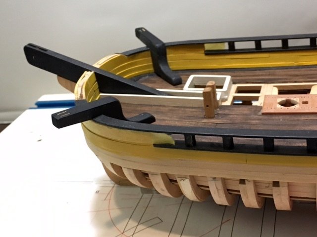
 I redid the catheads, going to the design seen on Chuck's Cheerful. They look much better now. Another two coats of paint needed and the sheaves need attention. Still mulling over the issue with the shrouds. Maury
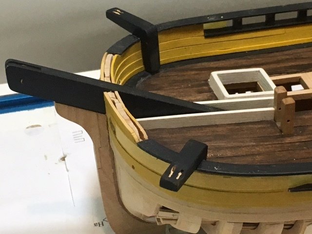
- 525 replies
-
- 10
-

-
- anchor hoy
- hoy
- (and 1 more)
-
Good to see you back. Maury
-
Cutter / Sloop shroud rigging problem on Anchor Hoy
Maury S replied to Maury S's topic in Masting, rigging and sails
Thanks for the comments. Pictures welcome. Mark, duties were primarily confined to harbors, but they ventured out from time to time and they had to be able to handle modest seas. Anchors were lost near mouths of harbors frequently as ships waited for tides to carry them in. Spyglass, I did not mention that the hoy has running backstays with no illustration of a realistic attachment. Running backstays were critical on the boats I raced a decade ago and there is very limited support for the top mast beyond a fore stay and those stays. Maury -
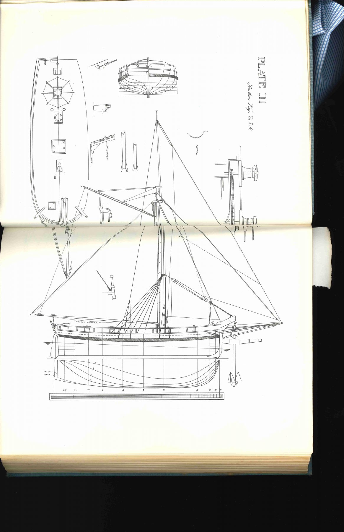
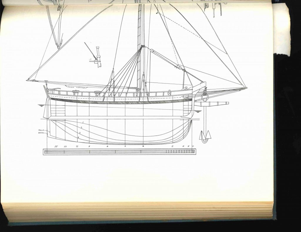
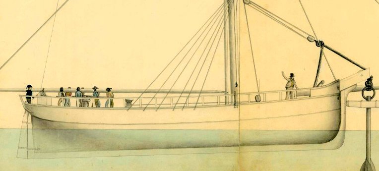
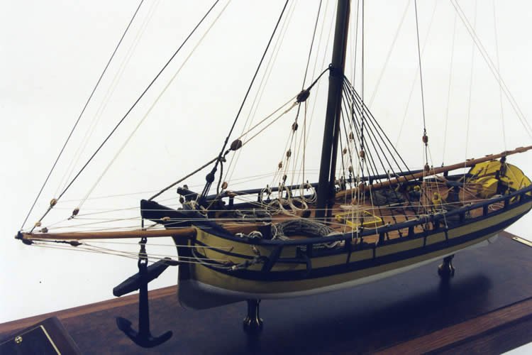
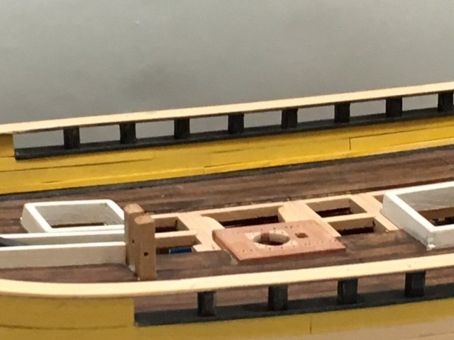
This issue has been touched upon in the Scratch Built Log https://modelshipworld.com/index.php?/topic/13002-anchor-hoy-by-maurys-pof-harbor-craft-c-1825-148/, and I thought we might get some fresh eyes and minds on the "problem". The model is based on Francis Grices' drawings from the National Archives for a boat he designed and built in the early 1800s at Norfolk. An enlarged section of one of the two drawings is shown below. The drawings, while detailed in some ways are not so in others. This leads me to think he drew them or had them drawn to illustrate just a couple of key issues with the boat. One being the support for the great cat at the bow and another the gearing connected to the two capstans (Not shown on this illustration but visible at the link above). No rigging related to the bowsprit appears. As can be seen on the picture above, the shrouds pass outside the rails but nothing is shown as to how they set up...channels, chainplates, deadeyes, etc.. There are two other sources of info. (I think one based on the other). Grimwood's American Ship Models (circa mid- 1900s) and Cairo's NRG articles circa 1970s clearly show the shrouds setting up on themselves at eyebolts in the waterway (Hence inside the upper rail). See following picture. Setting the shrouds outside the rail would require channels to hold the eyebolts or deadeyes far enough out so shrouds would not bind on the rail. None are shown. Having the tops of the shrouds around the mast only 20' above the deck to support the stresses of a large anchor mean they have a sharper angle to the deck so that supports the contention they setup inside (to the waterway). It also creates a much narrower arc through which the boom passes (limited to about 20 degrees either side of centerline). This would severely limit the ability to sail deeper than a broad reach. Druxey postulates that the two aft-most shrouds on each side set up with hooks into eyebolts so they could be removed while sailing giving more room to swing the boom. There are illustrations done by Grimwood and Cario that are clear mistakes (i.e. location of pumps), so they remain questionable sources, but I'm leaning toward their approach to the shrouds. Any input or comments would be greatly appreciated. Maury

-
Taking more of Druxey's good advice, I looked for more details on the original Grice drawings blown up 600%. I found a significant variation regarding the shrouds between Grice and both Grimwood and Cairo. Grice shows the shrouds outside both rails but no detail as to how they setup. The other two clearly show them inside the top rail (setup to eyes in the waterways). Grice is careful to show other items behind the rail where appropriate. To be outside, they would bind on the upper rail if not set to a channel which is not shown. Unlikely arrangement for standing rigging. But there are some other things not shown on the original drawings...topmast stays, wales, bowsprit rigging, etc...Comments encouraged! Maury
- 525 replies
-
- 6
-
-
- anchor hoy
- hoy
- (and 1 more)
-
Thanks Druxey. The "L" shaped catheads are easy to correct. I assume the port side would be the same (except for the bowsprit running beside the stempost). Maury
- 525 replies
-
- 3
-
-
- anchor hoy
- hoy
- (and 1 more)
-
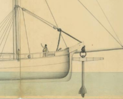
A close examination of a 400% enlargement of the original Grice drawing shows both a cathead and two hawse holes. (Why two?) Look carefully at the above view and you can see the cathead and what appears to be two holes...one above and one below the main rail on the starboard side. The bowsprit would be at about the same level as the upper one on the port side. There is a lot missing from the drawings...bowsprit rigging details...and I can make that adjustment. Thanks for the comments!!! Maury
- 525 replies
-
- 4
-
-
- anchor hoy
- hoy
- (and 1 more)
-
Druxey, I noticed that no catheads appear on the Grice drawings, and they do appear on the drawings from Robert Cairo's entries in NRJ...(the same drawings showing the elm pumps going through the deck where the gears would turn). They also appear on the plate in Grimwood's book and Erik Ronnberg's model (see below). All of the later sources have some flaws. Would not they anchor before attempting to recover a large anchor? Would not they anchor in a harbor with a tide that would move a boat away from its working spot? On smaller boats (35') I've sailed, we just brought the anchor line over the rail. On larger ones (65') there was a "cathead" of sorts on the bow....but there was always an anchor on board. I'm wide open to thoughts, and I'm inclined to fall back on Grice's drawings as the final arbiter. Thanks for all int input! Maury

- 525 replies
-
- 7
-
-
- anchor hoy
- hoy
- (and 1 more)
-
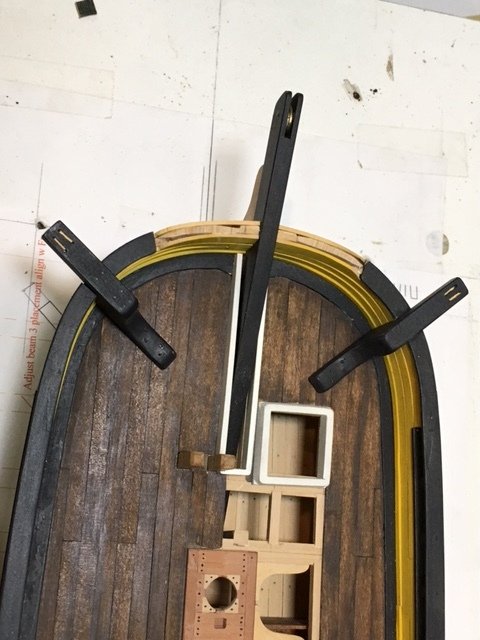
Once they were test fit, the cat heads seemed to be a bit too long and a bit "heavy". I shortened them about 12" (1/4" at scale) and tapered the top of the arm a bit. I'm happier with them now. I need to work on the simulated sheaves. The hawse holes are another matter. Just where to put them is wide open. None of the drawings available show them at all. Seems unlikely they would have just run the anchor hawse over the top of the rail. Maury
- 525 replies
-
- 10
-
-
- anchor hoy
- hoy
- (and 1 more)
-
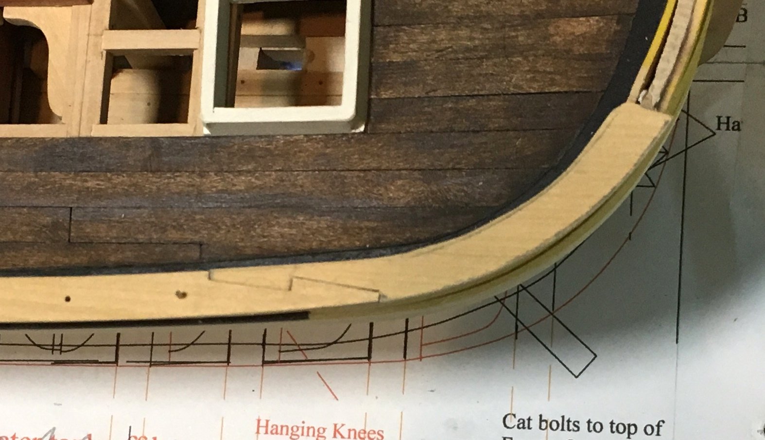
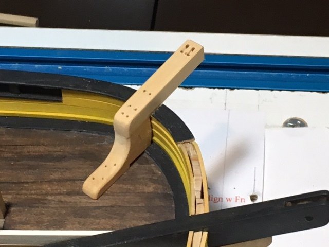
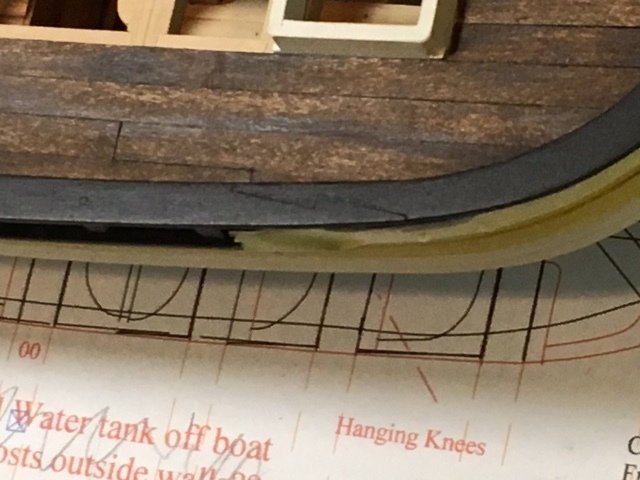
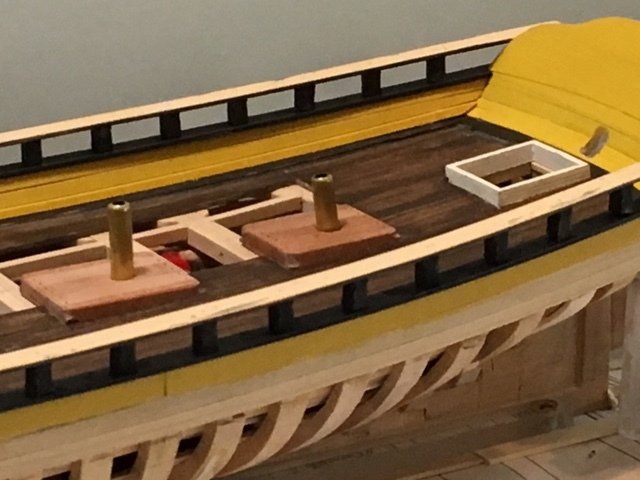
The cat heads have been completed. Test fit includes cutting out part of the upper rail so it rests on top of the frame top. A few minor adjustments, then paint. Note the space for water to drain where the cat base meets the waterway. Other things need attention. Where do lines run and belay? Eyes and rings at various places. Where should the hawse openings go? Lots of details to deal with. Maury
- 525 replies
-
- 8
-
-
- anchor hoy
- hoy
- (and 1 more)
-
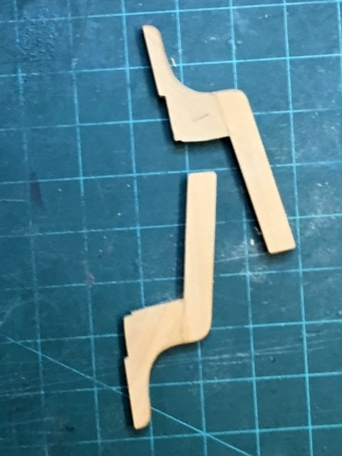
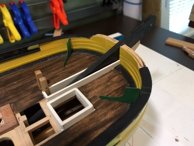
Next up are the anchor cats. Traditional placement and maybe a hair over-sized (measurements taken from Yedlinski's summary of Steele for a boat of approximate size). Card is easier and more efficient than wasting wood. Maury
- 525 replies
-
- 11
-
-
- anchor hoy
- hoy
- (and 1 more)
-
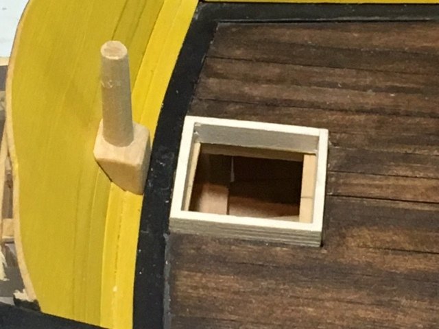
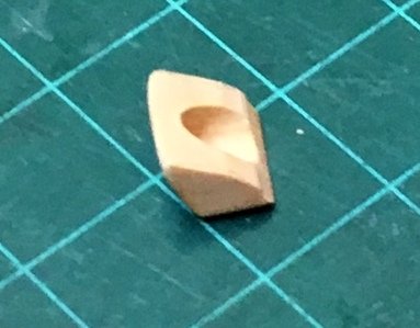
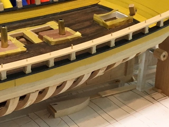
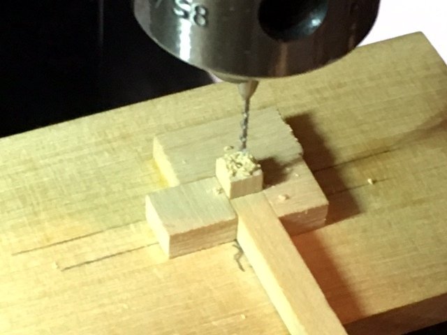
The original Grice drawing appears to show a "plug stock" rudder. See the discussion on Feb. 13 (log posts 275, 276). A round rudder post goes through a round hole in the counter / transom, thereby reducing the amount of water taken in through the hole. I had carved out the counter to accept the (original) rectangular rudder. That needed to be filled up and the rudder post needed building up and rounding. The rudder was easy to build up a bit and round out to a 9" (3/16" @ scale) diameter post. Aligning a round hole with the post was another matter. I chose to build a block with a correctly sized hole and fit it to the counter / transom. I started with a piece of 1/2" square stock, marked the end-center and bored a small starter hole with the mill. Working up through 4 or 5 sizes, I finished at 3/16" bore. I marked a rough profile of the counter / transom and started chiseling and sanding away. The final piece got beveled a bit on the top so water would run off. Second mate calls it another "cute" piece. It will not be permanently attached until the pintles and gudgeons are done and the rudder set. Color to be yellow ocher. Block is on its top, showing profile for transom
- 525 replies
-
- 8
-
-
- anchor hoy
- hoy
- (and 1 more)
-
The upper rails have been given another two diluted coats of paint (MS Hull/Spar Black). The scarf joint near the bow is clearly visible at this magnification. Now off to work on a rudder issue. Maury

- 525 replies
-
- 9
-
-
- anchor hoy
- hoy
- (and 1 more)
-
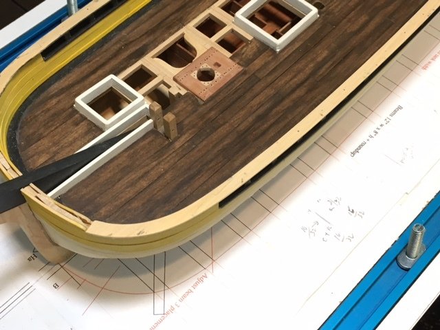
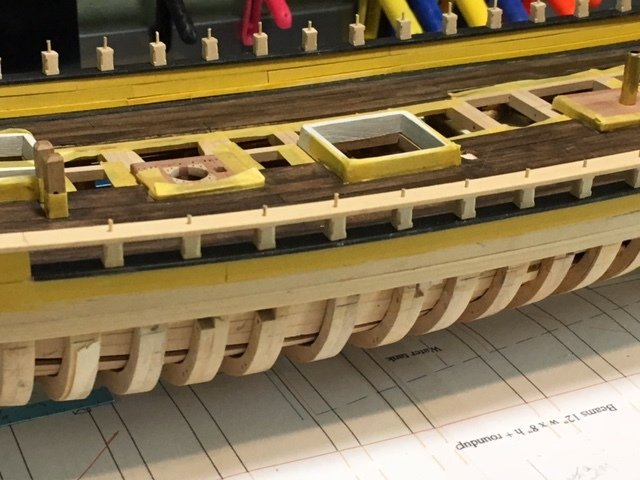
The stanchions and bottoms of the rails are painted and the rails are test fitted. And more from the side... The tops of the stanchion tenons are clipped and sanded off and the stanchions are glued in place. Maury
- 525 replies
-
- 10
-
-
- anchor hoy
- hoy
- (and 1 more)
-
The upper rail continues over the bow section. A piece was marked and roughly cut to shape. The scarf joint was started on the long piece (all those aligned tenon holes). After it was cut and finished, the two pieces were put in place and the mating shape was marked on the curved piece and cut. Both pieces' width needs thinning a bit before painting. That will obscure the joint for now. Maury

- 525 replies
-
- 9
-
-
- anchor hoy
- hoy
- (and 1 more)
-
More for us to try to achieve. Lovely work. Maury
- 3,618 replies
-
- 3
-
-
- young america
- clipper
- (and 1 more)
-
I test fit the upper rail. It had to be done with stanchions in the upper rail then fit to the main. When I get around to a permanent install, the glue will have to be S L O W drying. Ed Tosti mentioned that white glue has less rigidity / brittleness. That may be the way to go. Maury
- 525 replies
-
- 9
-
-
- anchor hoy
- hoy
- (and 1 more)
-
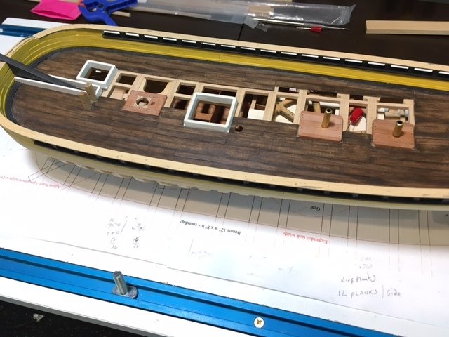
Work on the stanchions...There are 18 stanchions on each side, 7-1/4" square and 11 -1/2" tall (between the two rails). First the long piece was cut on the table saw, finish-sanded to the proper sides then chopped off using a sled on the table saw. Final sizing length was done on the "shooting board" sander. Each has a tenon, top and bottom. I made a jig for the mill, three sides rigid to the size of the stanchion, last side open. The mill was setup with the center of the stanchion centered. The long piece sticking down holds the stanchion firmly in the jig while being drilled. I bored from both ends to make sure centers matched. Tenons were made using bamboo and the Byrnes Draw Plate, inserted through the stanchion with a dab of glue and wiped off. Temporary installation shown below. The vertical corners will get sanded off and the pieces painted black. Maury
- 525 replies
-
- 13
-
-
- anchor hoy
- hoy
- (and 1 more)
-
No pictures for a few days...the computer has been in for a tuneup. THe upper and main rails were shaped and stanchion pins drilled while they were taped together. Sheer planks and main rails painted and glued. Maury
- 525 replies
-
- 9
-
-
- anchor hoy
- hoy
- (and 1 more)
-
Amazing joinery! Maury
-
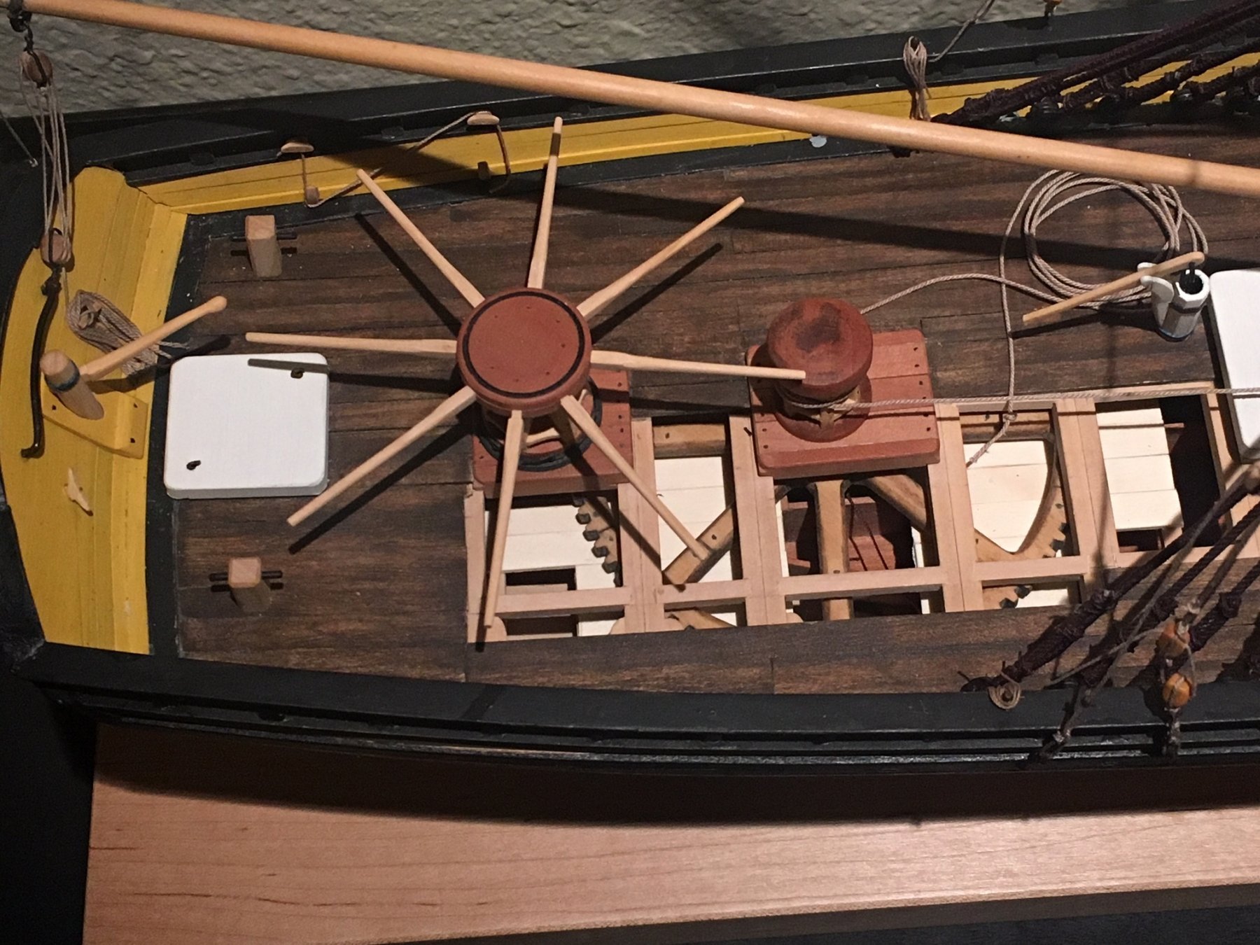
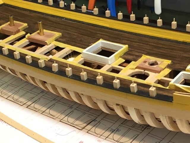
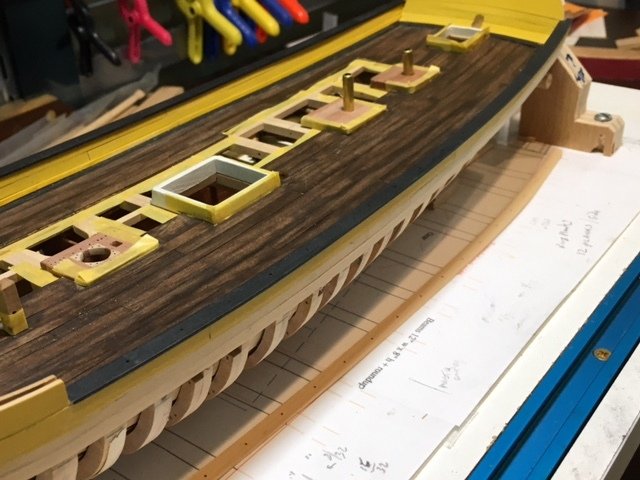
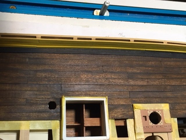
Thanks for all the "Likes" and especially the comments. The deck planking has been re-stained. The variation in color is a result of having scraped the planks earlier, then staining over them. There were some planks that were still "too light" so I just stained over them again to bring the variation to how I wanted it. Brush it on and wipe off right away. I went through a dozen Q-tips. Personal choice. The masking tape is Tamiya, well burnished. The joint between the planking and the waterway (barely visible) is caulked with Ebony Minwax putty and rubbed off. A few touch-ups are needed on the black paint on the waterway. Maury
- 525 replies
-
- 15
-
-
- anchor hoy
- hoy
- (and 1 more)
-
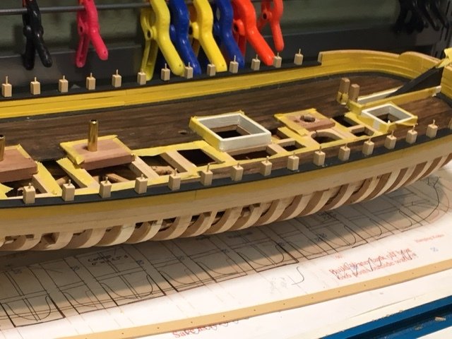
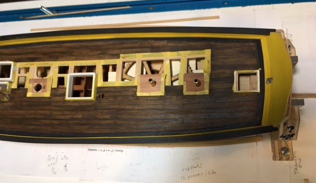
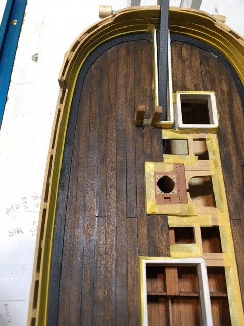
The deck planking is installed and scraped. It gets another coat or two of stain. I'll see how I like the mottled look as I move along. The finish is quite different on boards that were scraped vs. those just sanded. A lot of masking to do to prevent bleeding into beams or bitts, etc. before I apply any more stain. Maury
- 525 replies
-
- 13
-
-
- anchor hoy
- hoy
- (and 1 more)