HOLIDAY DONATION DRIVE - SUPPORT MSW - DO YOUR PART TO KEEP THIS GREAT FORUM GOING! (Only 20 donations so far - C'mon guys!)
×
Maury S
-
Posts
1,490 -
Joined
-
Last visited
Content Type
Profiles
Forums
Gallery
Events
Everything posted by Maury S
-
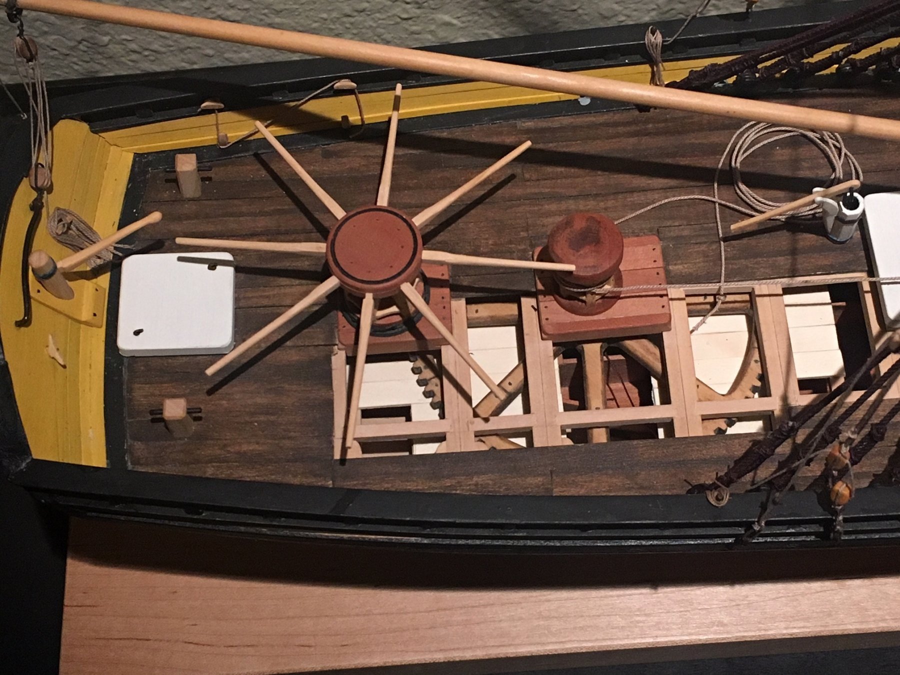
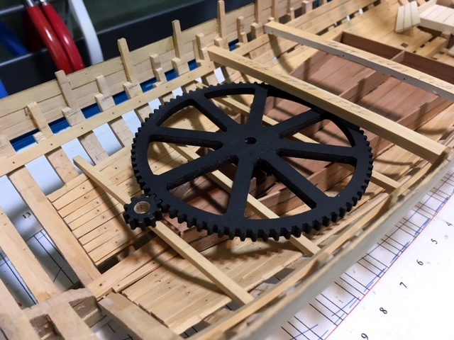
 With special thanks to Roger, I re-worked the gears as built-up wooden gears. The joints are simulated and the bolts are 20 pound mono- filament line. The lighter parts in the center are a reflection of the light above...not a different color. They are certainly more interesting this way. Maury
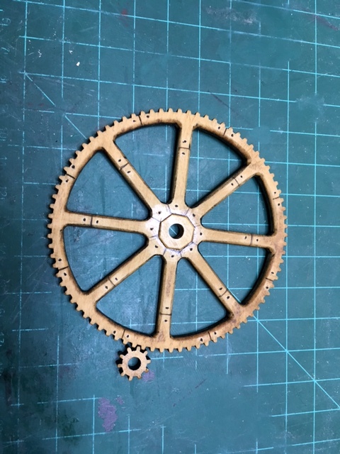
- 525 replies
-
- 15
-

-
- anchor hoy
- hoy
- (and 1 more)
-
Roger, Thank you for the comments. This is invaluable information and I am so glad to have received it. The link and pictures of the mill with the large wooden gears now have me leaning towards displaying it as such. I would include one of the pictures, but do not want to step on the copyright. See the link: http://www.whitemill.org/z0012.htm It's just a matter of sanding the black paint off the pieces and simulating joints. I love this organization. So much help from so many people. Maury
- 525 replies
-
- 7
-
-
- anchor hoy
- hoy
- (and 1 more)
-
Roger, Thanks. I have not way of knowing whether the gears were a solid casting. The only thing we have is the Grice drawings (see first post on this log). I doubt the gears were wooden with wear considerations, but built-up parts or metal gears on a wooden axle are certainly possible. If anyone else has a information please add a comment. Maury
- 525 replies
-
- 2
-
-
- anchor hoy
- hoy
- (and 1 more)
-
Thanks for the likes and comments. Toni, laying out the gear deck and main deck planking to expose the gears is a primary goal. I've sanded off some of the hard edges of the gear and it looks better...picture to follow. I'm not sure, but I think that having the axles of the gears going down to and bedding at the keelson transfers some of the weight of the massive gear to lower in the hull. Engineers out there feel free to chime in. Maury
- 525 replies
-
- 2
-
-
- anchor hoy
- hoy
- (and 1 more)
-
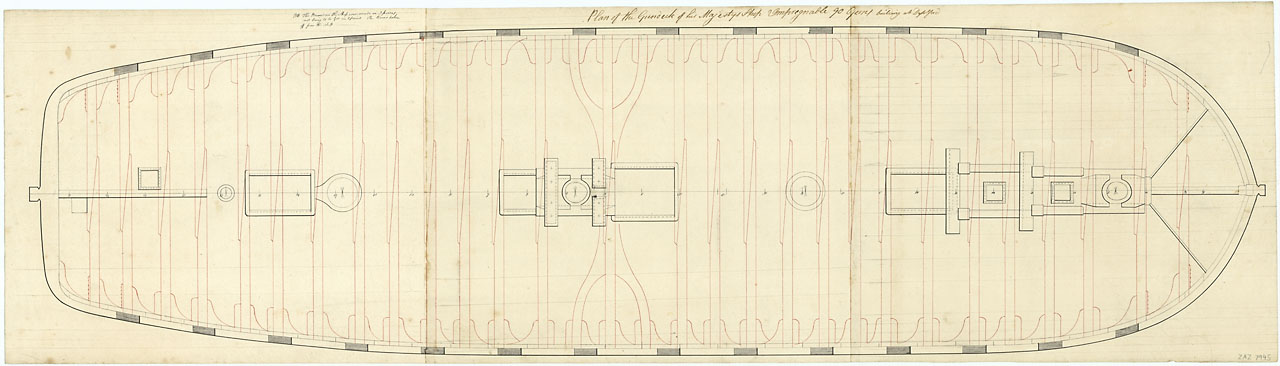
Mark, the large gear is 14' diameter and the ratio between the gears is 8:1. The original Grice drawings show it a bit larger, but it would not have fit abeam at that size. Maury
- 525 replies
-
- 3
-
-
- anchor hoy
- hoy
- (and 1 more)
-
Chuck, VERY nicely done. Re: "One interesting feature to point out might be how the blocks are hooked to thimbles/bullseyes on the gaff. " Could you provide an enlargement of the thimbles / bullseyes? Maury
- 1,051 replies
-
- 3
-
-
- cheerful
- Syren Ship Model Company
- (and 1 more)
-
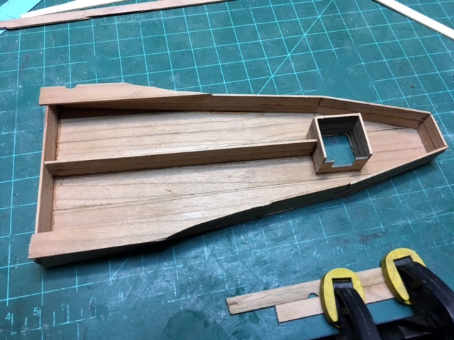
It's been a busy day. The water tank is almost done. It probably had a top. I'll put a few planks to illustrate. It needs a (left to right) divider at the end and another (top to bottom of pic.) closer to the front to provide four separate sections. The tanks of the era were of cedar. I used some scrap cherry to get a different color. It's going to be called red cedar. There is a well in the middle of the tank protecting the axle of the fore capstan. It has one side cut-out for display. More test fitting of parts...I've been holding this back for several months. One of the features that attracted me to this boat was the gearing of the capstans. Chuck Passaro made the gears for me on his laser cutter. There are beads on the under side to represent ball bearings. They will fit on a "race" on top of the gear deck floor. There will be enough room between the bottom of the beam and the top of the gear. Careful planning. Maury

- 525 replies
-
- 12
-
-
- anchor hoy
- hoy
- (and 1 more)
-
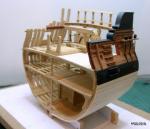
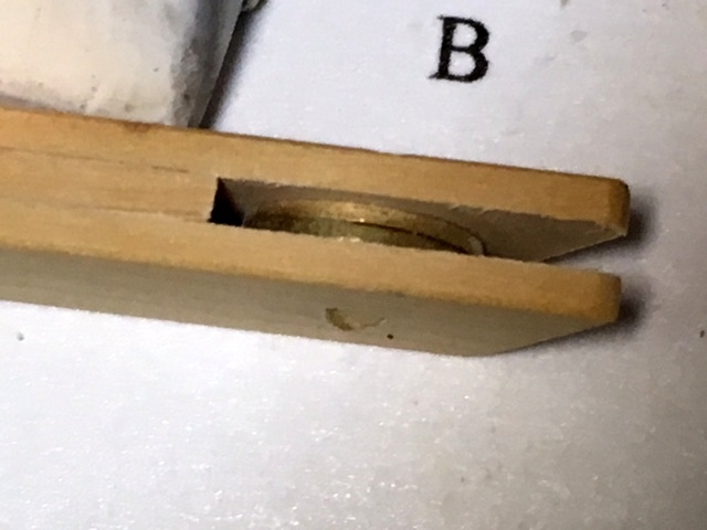
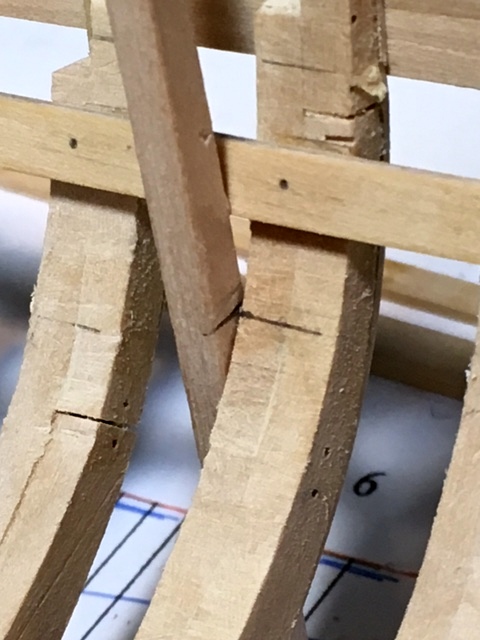
Slow progress over the last two weeks with other obligations. Working on the balance of the ceilings up to the main deck clamps. While waiting for paint (clear coat) and glue to dry I've found diversions in the water tank, the floors of the forward hold and lining up the correct heights of the bowsprit bits and the great cat bits. The cat was assembled earlier. The sheave is two small brass washers. The floor will sit on two of the forward half frames and will eventually be in two levels, side to side. It's holly and may be painted or stained later. Then came the lining up of the bitts. I cut and sanded two test beams to the molded and sided measurements. The height of the bowsprit bitts above the deck is specified and they anchor on the frame. The cat bitts extend from the side of the keelson to the bottom of the deck beam just forward of the mast. The beam needs to align there and allow room for the great cat to pass through the deck. Maury


- 525 replies
-
- 11
-
-
- anchor hoy
- hoy
- (and 1 more)
-
Michael, do you have a chart of temperatures for various woods or thicknesses? Maury
-
Ed, Great explanation. So each band was individually sized, tight to it's position on the mast. How did you get it in place without scraping the mast as you forced it in place? Is the copper that soft? Maury
- 3,618 replies
-
- 4
-
-
- young america
- clipper
- (and 1 more)
-
Druxey, Thank you. Yedlinsky gives scantlings for knees of various decks and boat size. For the upper deck, 5" sided and about 3' for the athwartship arm (for a or cutter...no hanging knee shown for a 300 ton sloop) . That would be close to your suggestion of 1/6th beam length. A bit longer for hanging arm on hanging knees. "Beams to be kneed at each end with 1 hanging and 1 lodging knee". Do you think the same standard (Lodging and hanging knees at all beams) applied to a sturdy "work boat"? Maury
- 525 replies
-
- 4
-
-
- anchor hoy
- hoy
- (and 1 more)
-
It was part of the search for "Lighter" and the only one I found with knees visible. Maury It does look to be a larger ship. If the dark areas on the edges are gunports, then it's clearly not a service boat. M
- 525 replies
-
- 2
-
-
- anchor hoy
- hoy
- (and 1 more)
-
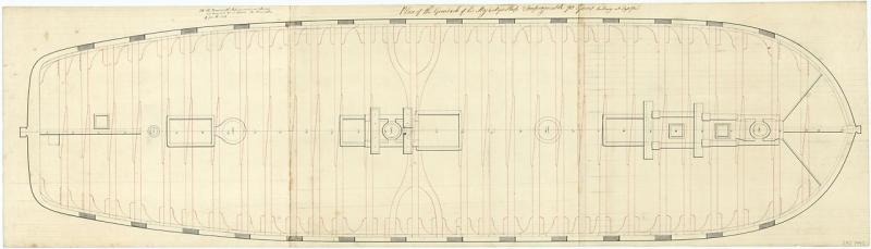
Some revisions to the plans. I checked prints of grossly similar boats of the same era on the Royal Museums of Greenwich (the old National Maritime Museum) site for layout of knees. I only found one applicable print out of about fifty links. It seems the pattern is as follows: Forward of deadflat, hanging knees are attached to the fore face of the beams and lodging knees on the aft face; aft the deadflat, the pattern is reversed. Since there was only one print, I do not know if the pattern was standard. Pdf file of the Hoy beam-plan is attached. There are a few spots (around the mast and capstans) where there are mirrored lodging knees and no hanging knees. Maury AH_DeckBeams2.pdf
- 525 replies
-
- 5
-
-
- anchor hoy
- hoy
- (and 1 more)
-
Druxey, I was going to put a molding piece over the ends of the "hanging planks" rather than cut them back to the earlier frames. Frankly I never thought of cutting them back. Would that be the way they were done? Leaving a gap to the next frame? Bob & Dr. Per, The little clamps are cut-apart planking clamps I bought from Modelshipways years ago and found useless as they were originally designed.
- 525 replies
-
- 3
-
-
- anchor hoy
- hoy
- (and 1 more)
-
Beautiful! Why was the step tenon not done at the same time and method as the mast-head trimming? Maury
- 3,618 replies
-
- 1
-
-
- young america
- clipper
- (and 1 more)
-
More time spent on the interior planking. Several strakes from bottom up and two top-down at the forward section. Special treatment will be necessary around the gear-deck clamps. Most of this work will be covered up but you all and I know it's there. (please notice I did not use the term "y'all"). Maury
- 525 replies
-
- 8
-
-
- anchor hoy
- hoy
- (and 1 more)
-
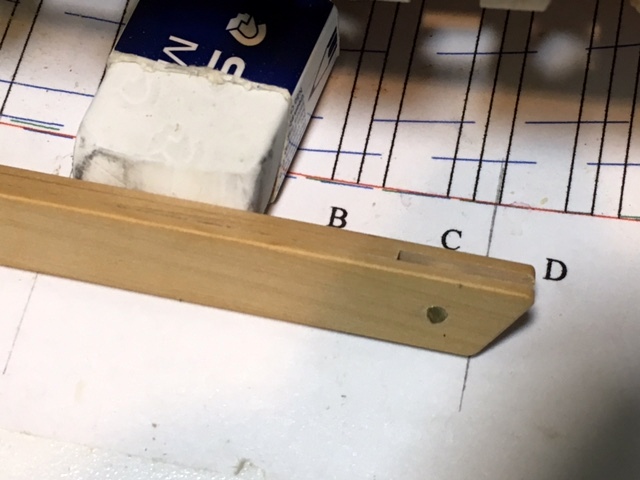
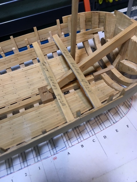
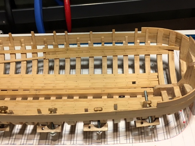
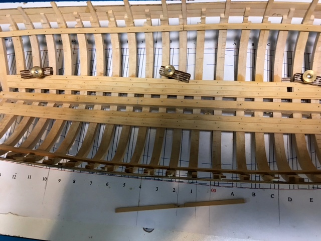
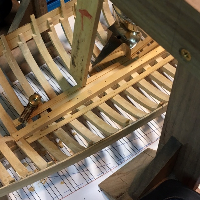
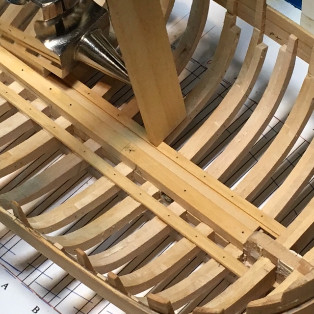
Druxey, THANKS for pointing out the wiggle. I laid a batten across the clamp and found it a bit low at frames 2 and three. Back to the ISO. Thank goodness for a camera lens and a fresh set of eyes! I worked on the clamps for the gear deck. I need 14.5" clearance below the lowest bottom of the deck beams for the gear, bearings and floor of the gear deck. Frame #5 is the lowest in the area of the gear. A 15" pattern block was held under a temporary deck beam at Fr. #5 to establish the top of the gear deck beam (bottom of the floor) at this place. The gear has to be parallel to the top of the keelson (not the main deck). A measuring stick was held at frame #5 (see first picture) and the height from the building board was marked and then transferred to the other side and to both sides of frame #12 (the farthest extent of the gears). Putting the top of the gear deck clamps on these marks assures it is parallel to the keelson. The clamp was held in place on both sides, temporary beams laid across the and a wide, flat piece (it's the bottom of the water tank) was laid over the beams to check level and flat. Then the temp. floor and beams were removed. Before the clamp was glued in place, the upper edge was eased in a rolling manner from front to back so the beams would rest on a flat surface, not just the corner of the edge. I'll run a long sanding stick across the tops of the clamp (side to side) where the beams lay before final install. Notice in the third photo how much difference (from level) there is between the main deck clamp and gear deck clamp. Now I'm sure the capstan axle will be perpendicular to the keelson.


- 525 replies
-
- 13
-
-
- anchor hoy
- hoy
- (and 1 more)
-
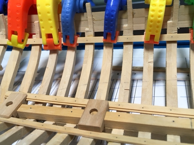
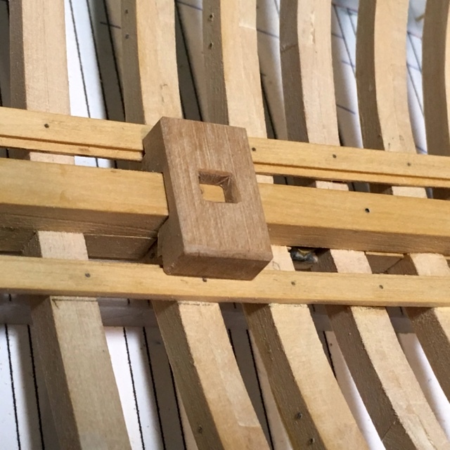
Working on the ceiling planks. There are 12 strakes from limber to clamp. Using a planking fan, three frames (12, 00 and E) are marked with tick strips (see the dim tick marks at far left and far right of photo) . The taper is modest. The three frame locations are marked on the plank, and a tick strip used to set the width. A ships curve used to mark the taper on one side. A disk sander is used following the taper line, and fine adjustment is done by hand sanding. The square hole on the port side (upper right) is to accommodate one of the bowsprit bitts. The dark area on the frames is water from cleaning up the glue joint. I have to get the clamps for the floor of the gear cabinet set properly before planking down from the main clamp. That involves measuring down from the bottom of the deck beams to allow for the height of the massive capstan gear (more on that later). Maury
- 525 replies
-
- 13
-
-
- anchor hoy
- hoy
- (and 1 more)
-
Ed, Beautiful. Will you elaborate on the "7/24" scriber. That's the same as 7-10-7 line-out that we're familiar with but having the tool might help. Once made, it will work on all spars, but how did you make it? Maury
- 3,618 replies
-
- 6
-
-
- young america
- clipper
- (and 1 more)
-
hss vs carbon steel drill bits
Maury S replied to Kurt Johnson's topic in Modeling tools and Workshop Equipment
Keep in mind Carbide bits are very brittle and will not take any side-load without breaking. I use the carbide bits from Drill Bit City, but only in the drill press. For the pin vise, only hss bits. They are more forgiving if your hand is not rock steady. I tried the carbide bits in my Dremel right angle accessory and just the kick at the start was enough side load to snap them. Maury -
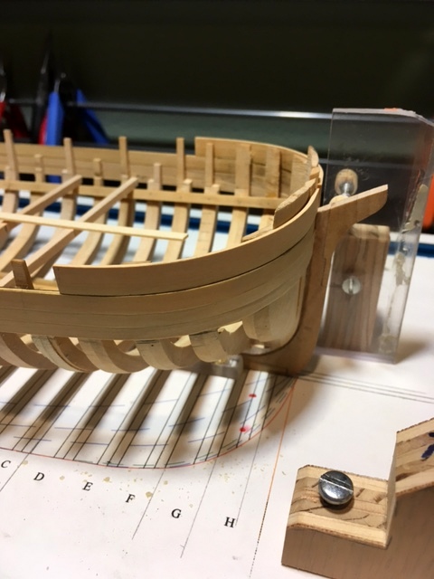
The fore top bulwark (if it has a name, I've forgotten) is bent and installed. It is 15" by 2.25". Scantlings for boats of this approximate size show one plank (up to about 16"), not two. It terminates at frame "E." I have abandoned boiling prior to bending any pieces that will be visible. Chuck Passaro has convinced me that heat alone works, and shrinkage as a result of the water is minimized and raised grain is gone. I use a plank-bending iron and a hair dryer. Just to check out the accuracy of the clamps, I laid some flat "beams" at several locations and set a long wide thin board across them. All is fair for the deck! Maury
- 525 replies
-
- 15
-
-
- anchor hoy
- hoy
- (and 1 more)
-
Thanks for all the "likes" and comments. I installed the clamps and cleaned up the keelson and assorted frame parts where the remnants of the spacers still showed. The clamps will have at least two actual treenails per plank for additional support, the rest are simulated as described earlier. The mast and capstan axle steps needed re-working with the limber planks in place. I was drawing the capstans and after looking at the scantlings in Steel's "Elements...." I thought maybe I over-sized them for the size of the boat, but then realized they have to be large enough to handle the anchors of the large ships. My original sizing seems appropriate. Maury
- 525 replies
-
- 14
-
-
- anchor hoy
- hoy
- (and 1 more)
-
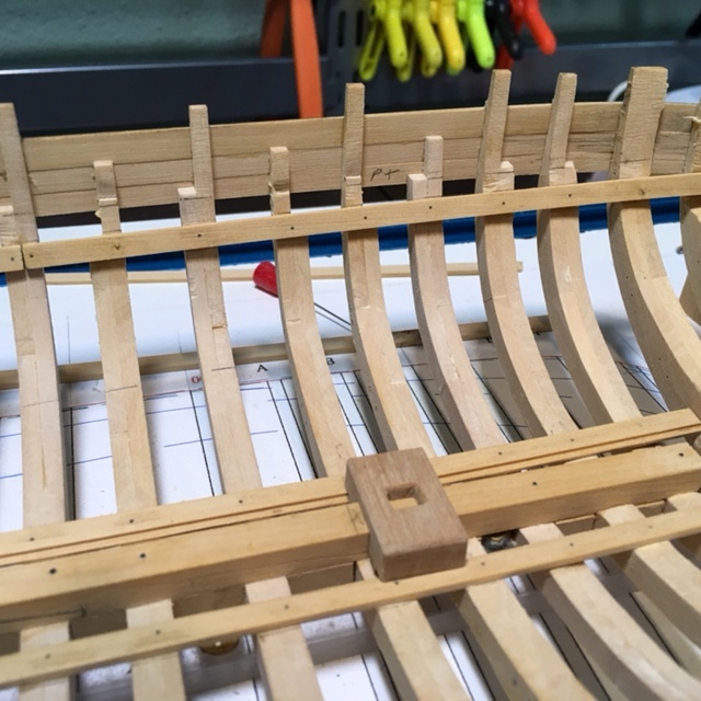
The limber planks were installed using hold-downs from the gantry above, clamps through the frames and heavy weighted objects. A 9" spacer plank can be seen between the keelson and limber on the port side (upper in the picture). It is removed once the glue is set. Maury
- 525 replies
-
- 11
-
-
- anchor hoy
- hoy
- (and 1 more)
-
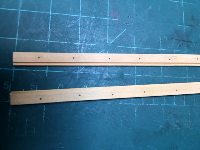
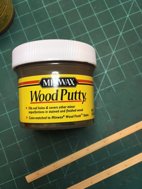
Before going further, I reviewed my Echo Section project instructions to confirm the order of things. The limber plank needs to go in, so I looked up sizes in Steele and came to an approximation based on the smaller gun ships. A 3 1/2" x 10" plank with a 9" separation from the keelson. The rabbet was cut on the table saw, plank laid in place to determine frame locations, and holes drilled (#73 drill) while off the boat. I put on a coat of clear finish (Rustoleum Poly matte, water based), then filled the holes with walnut colored wood putty to simulate treenails. The clear coat prevents the putty from staining the area surrounding the holes and can be lightly sanded off afterwards. I used the same method on the Echo section and it worked well. Maury
- 525 replies
-
- 10
-
-
- anchor hoy
- hoy
- (and 1 more)
-
Planning...I've been reviewing Robert Cairo's series on Service Craft (NRJ 1976 - 1978) as well as several Theses from the Nautical Archeology Dept. at Texas A&M. The water tanks seem to have been made of cedar until around 1835 +/- (when iron tanks were introduced) and were compartmentalized to minimize the water moving around and affecting the handling of the boat. Knees are another issue. Very few drawings of service craft show much detail in framing, etc. Some show lodging knees at beams in stress areas (mast partners, etc.) but very little about hanging knees. Similarly, the reports of Excavations of merchant ships of the era seem not refer to hanging knees. I see references to lodging knees, described down to a mm in thickness variations. It seems dimensional standards for merchant boats were quite lax. Grice designed and built warships under contract with the Navy, so I'm sure his yard held reasonably strict standards for anything they built. Anyone have a reasonably good idea on knee arrangements of the early 1800's for American, merchant boats? Maury
- 525 replies
-
- 2
-
-
- anchor hoy
- hoy
- (and 1 more)