HOLIDAY DONATION DRIVE - SUPPORT MSW - DO YOUR PART TO KEEP THIS GREAT FORUM GOING! (Only 20 donations so far - C'mon guys!)
×
Maury S
-
Posts
1,490 -
Joined
-
Last visited
Content Type
Profiles
Forums
Gallery
Events
Everything posted by Maury S
-
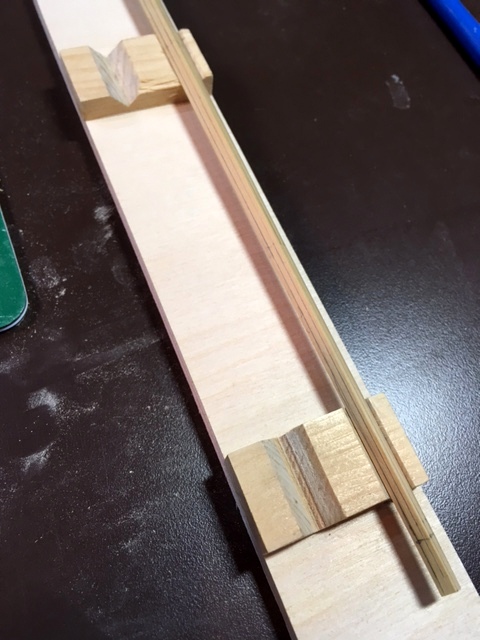
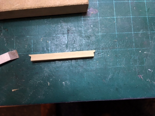
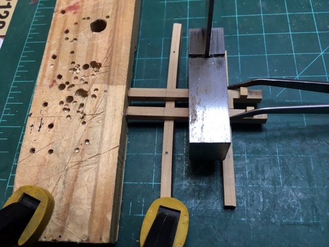
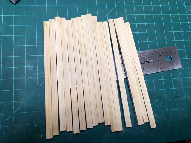
 I am without power tools for a while so I'm working on the spars. I cut and sanded several pieces to the extreme width of each spar. Next comes tapering them and then cutting them down to 8-sided. that involves using the 7-10- 7 fan and planing down the four corners to 8. You can see the lines as the stick lies in the jig (thank you Admiralty Models) ready for planing. Maury
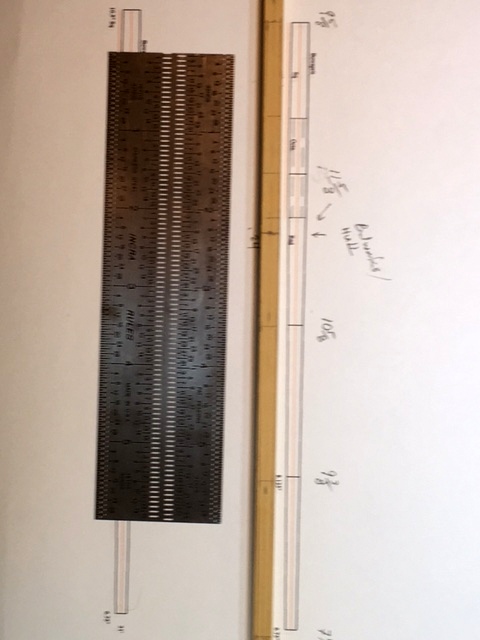
- 525 replies
-
- 11
-

-
- anchor hoy
- hoy
- (and 1 more)
-
I think it was Ed Tosti's recent posts that had me awake thinking about the spencer mast. If anyone has any drawings of how the mast seated, please share. Thanks for all the likes and especially the comments. Maury
- 525 replies
-
- 2
-
-
- anchor hoy
- hoy
- (and 1 more)
-
Druxey, Thank you. I can find a block of wood somewhere in the scrap bin. Just a morticed block bolted to the deck on top of the partner?
- 525 replies
-
- 2
-
-
- anchor hoy
- hoy
- (and 1 more)
-
It's a good thing I lay awake thinking about the plans...I forgot to add the step for the spencer mast to the partners. It is an 8 5/8" diameter mortice in the partners about 2" aft the main mast. Maury
- 525 replies
-
- 2
-
-
- anchor hoy
- hoy
- (and 1 more)
-
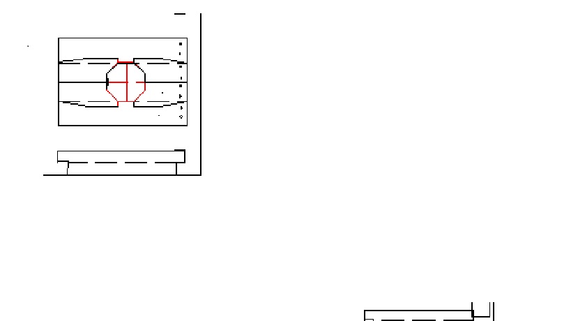
Mast Partners. I've reviewed the details of mast partners from TFFM. I'll use the same basic layout, adjusted to fit between the deck beams. That involves locating where the mast passes through the deck. I used the gantry again to line up a temporary mast (square section at the largest diameter is at the partners). Allowing for a very slight rake, I now know where the hole in the partners needs to be. Picture pasted in MS Paint looks crude, but you get the idea. There are some odd angles to where the cross chocks meet the carlings and the partners will be visible, so special attention needs to be paid. The hole will be rounded and a bit larger than the mast to allow for wedges. Maury

- 525 replies
-
- 12
-
-
- anchor hoy
- hoy
- (and 1 more)
-
The knees are in place for the first four beams. If I keep going fore to aft with the beams, I think I have to get the mast partners drawn up and installed. I have the layout of partner pieces from my Echo Section build. Seems a reasonable place to start. I'll pull more info. from Yedlinsky. Lining up the hole with the mast step needs to be done, so a temporary mast needs to be set. Maury
- 525 replies
-
- 16
-
-
- anchor hoy
- hoy
- (and 1 more)
-
Thank you all for the likes and especially the comments. Gary, the boat is certainly interesting and it's proving to be a great modeling experience. I no longer strain at the bit and get impatient. Of course three masts and 34, or even 16 guns would probably change that. "Each piece is a model unto itself." There are plenty of mistakes along the way, and I'm very grateful foe all the help and comments. Maury
- 525 replies
-
- 5
-
-
- anchor hoy
- hoy
- (and 1 more)
-
The carlings and beams are in place. Knees are next. Then I'll move aft with more beams. It will soon be time to lay out the partners. Maury
- 525 replies
-
- 15
-
-
- anchor hoy
- hoy
- (and 1 more)
-
I love the discussions. So much knowledge here. More work on the beams. Since the great cat passes thru what would be the center of beam #2, carlings had to be installed to support the beam parts. From work on my Echo Section, I learned a very effective way of creating mortices and tenons. They are cut on an angle at the top as is the deck beam. They then fit nicely into the angled slot on the beam. Slight differences in elevation can be sanded off easily. Notice the positions of the carlings are slightly different. The starboard one is parallel to and directly above the side of the keelson. The port one (shown below) is about 8" further to the side and passes between the two bowsprit bitts. The same technique will be used to connect the beam pieces to the carlings. Maury
- 525 replies
-
- 11
-
-
- anchor hoy
- hoy
- (and 1 more)
-
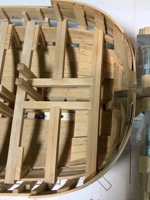
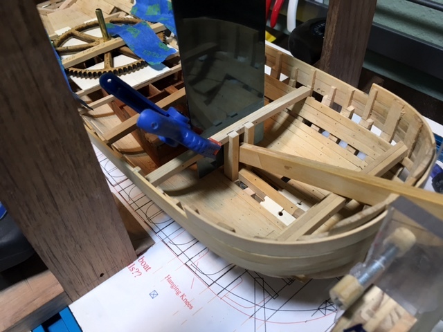
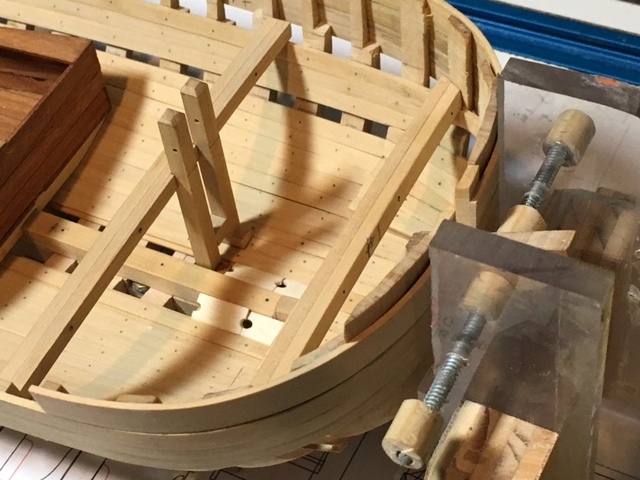
Starting on the beams and bitts. The gantry sets the position of the beam with a square set on top. The beam is notched and the bitts for the great cat are test fitted. After that beam and the bitts were glued in place I moved forward to the next beam where the bitts for the bowsprit line up from the keelson to the beam above. Again, the square on the gantry lines up the beam and the bitts are clamped and glued. All the knees have been rough cut on the jigsaw. I think the hanging knees go on the beam first, then the ledges. It's going to get tight in there. Maury
- 525 replies
-
- 11
-
-
- anchor hoy
- hoy
- (and 1 more)
-
You could always do it the way they were done in the real world. Start with square stock (thereby insuring no bend in the stick), mark the taper and with a "7 - 10 - 7 fan" and cut it down to 8-sided, (then 16 depending on scale), then sand round. This way you'll actually develop some very useful skills. Maury
-
Michael, There would be a "race" channel for the bearings to ride in. Probably an iron slot. Not sure how to represent it or if it would be visible if I put something in. Any ideas or suggestions are welcome. Maury
- 525 replies
-
- 2
-
-
- anchor hoy
- hoy
- (and 1 more)
-
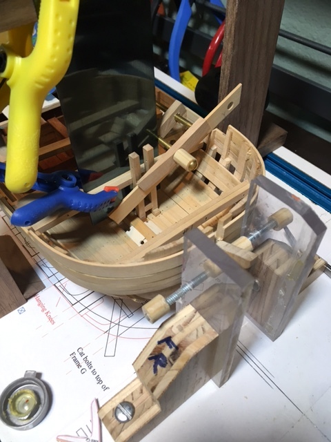
More work on the beams. Through-bolts are installed. Each beam will get lined up according to the beam plan, subject to any little positioning adjustments. The bowsprit bitts go from the frame at the edge of the keel / keelson through the deck and terminate 2' 3" above the deck. I installed a spacer to keep them parallel with the notches in the beam and did a test fit. Keep in mind, the bowsprit is off-set from center because of the great cat occupying that position. The bitts are the only things sticking out above the deck beams until I get to the deck furniture. I think I can protect them when the boat is off the building board, so cutting and fitting knees comes next. Maury
- 525 replies
-
- 9
-
-
- anchor hoy
- hoy
- (and 1 more)
-
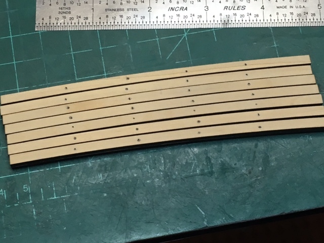
Construction of the beams has begun. First, there are 15 or so beams, all with the same shape (a rise of 1" in 20'). To simplify making exact copies, I had Syren Shipmodels http://www.syrenshipmodelcompany.com/ laser cut a full set. Well worth the cost. Since a width of 1 foot (1/4" in scale) was called for (from the Grice sketch), and the triangle shape of the laser beam might have an impact on the beam size of 1/4", I agreed to building up the beams from two 1/8" pieces. They were easy to match up and glue together to make a 8" x 12" beam. Laser char was sanded off and everything was trimmed to final size. I did a test of using dark glue or un-colored Titebond to put the two pieces together. The dark is just barely visible and the un-colored is not quite invisible. "If you can't hide a joint, show it off", to I went with the dark. The beams get thru-bolts and will be cut to size. I now have to give a lot of thought to the order of the next steps. Taking the boat off the building board to work on planking means risking anything sticking up thru deck beams (i.e. bowsprit bitts finish 2' 3" above the deck). Placement of the beams to line-up with some frames and to allow proper spacing for partners all has to be checked. Maury
- 525 replies
-
- 5
-
-
- anchor hoy
- hoy
- (and 1 more)
-
Mark, Great work. Is the bend on the right side of the hatch combings a lens distortion? Over the last many months I've take to using the camera on my iPhone (model 5 se. Same technology as the 6 in the smaller case). The pictures seem as good as the SLR versions of old. A lot cheaper than a new camera. Maury
-
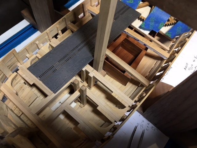
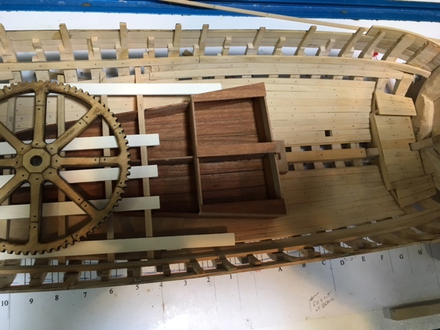
The water tank and the flat beams for the gear deck installed, with floor planking over, left open except where the race for the gear bearings goes. Everything lines up so far. Maury
- 525 replies
-
- 11
-
-
- anchor hoy
- hoy
- (and 1 more)
-
Roger, Thanks. I agree with your comments about the size of the main mast and intend to beef it up. The main mast was not even used to support the main boom and sail. The boat has a "Spencer mast" aft the main for that purpose. Your insights are greatly appreciated and are being incorporated into my build. I think taper proportions would still apply. Other elements of the drawings raise questions about the accuracy of the boat either as built or as planned. An example is the diameter of the main capstan gear as shown in the profile sketch is larger than the internal breadth of the boat. The bowsprit in the sketch seems grossly over-sized and that spar has no function in regard to the anchor hoisting...in fact, it was taken in when the great cat was in use. This is turning out to be a more interesting project than I envisioned and I'm grateful for all the support and input I'm getting along the way. Maury
- 525 replies
-
- 8
-
-
- anchor hoy
- hoy
- (and 1 more)
-
Ed, Thanks, I sent you a PM. I've ordered Crothers, but it's coming from the UK so it may be a while. Maury
- 525 replies
-
- 2
-
-
- anchor hoy
- hoy
- (and 1 more)
-
While waiting on a few items, I've started drafting the spars. I have the length of all spars, but no diameters. "Scantlings of ...Navy Ships" by Yedlinsky has no details about spars. I found some detail in "Merchant Sailing Ships 1775 - 1815" by MacGregor for a boat of similar length and breadth. The Grice sketches show the main mast and bowsprit much beefier than those. It's a sketch / drawing, not a lofted plan. Any advise on interpreting? Do I compromise somewhere between those measurements considering the heavy duty purpose of the boat? Tapering is another issue. I've used TFFM mast info for the main. Nothing about boom and gaff. There must be ratios in some source, but I do not have a full version of Steel. Maury
- 525 replies
-
- 3
-
-
- anchor hoy
- hoy
- (and 1 more)
-
I used Toni's suggestion of PVC pieces a few years ago and stored the wood vertically. Big mistake! The strips were bent within a month. I suggest you store it horizontally (as Toni prefers) and do not allow long ends to hang over the open end. Maury
-
You can get a cyclone system to supplement your vacuum and hardly ever have to change or clean filters. I bought a "kit" from these people with buckets, hoses, etc. https://www.amazon.com/Oneida-Molded-Dust-Deputy-Cyclone/dp/B0037MFZN0 I put the cyclone and vacuum on a handmade cart and drag it around to everything from my 10" contractors saw to the Byrnes thickness sander. Vacuums and tools are very noisy so I always wear headphones. Maury
-
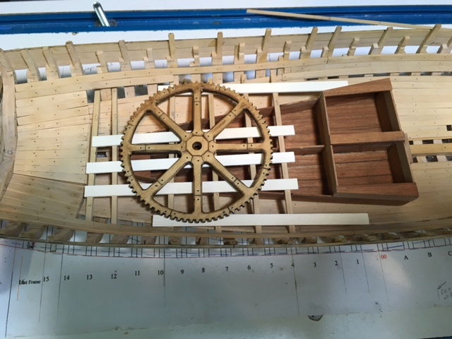
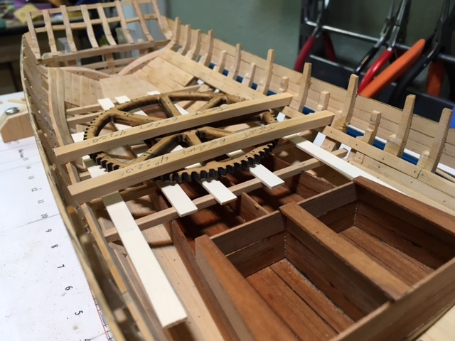
Thanks for the comments. As I indicated earlier, I had Chuck Passaro cut the gears on his laser cutter from Box wood. A fine job! After comments about the weight and casting such a large piece, I was convinced the technology at the time supported a built-up wooden gear. See the earlier post for the link to an English mill. (Thanks to Roger). Think of mill wheels or wagon wheels. It makes perfect sense. Joints would have overlapped. The gear turned out to be more interesting than a plain cast iron piece and since that's one of the big reasons for choosing this boat I am quite pleased with the decision to convert it to wood. Maury
- 525 replies
-
- 6
-
-
- anchor hoy
- hoy
- (and 1 more)
-
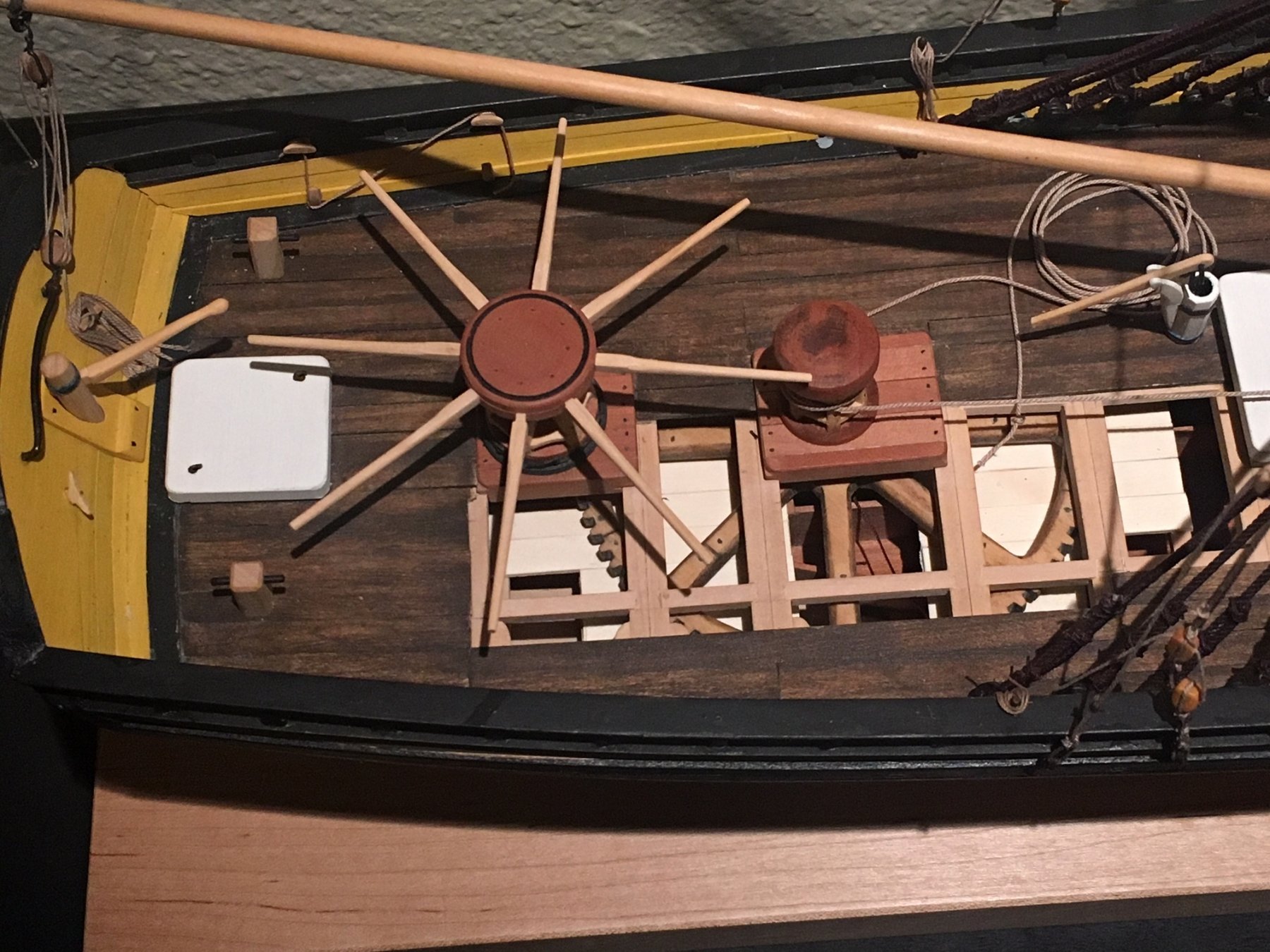
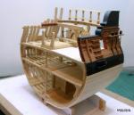
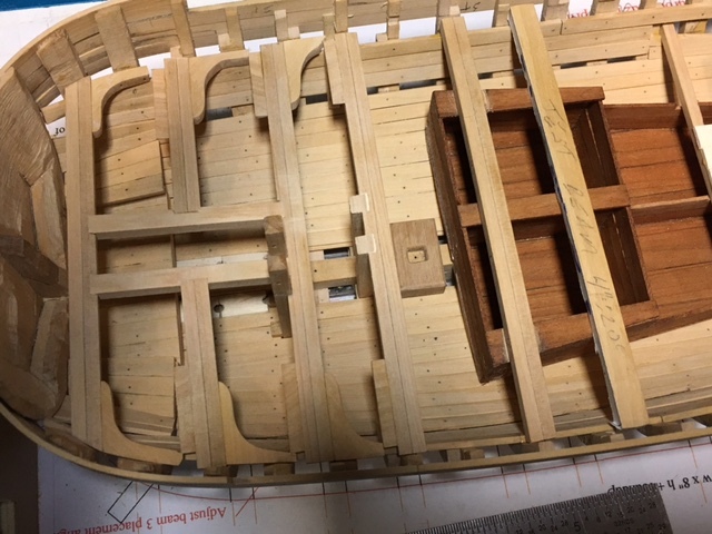
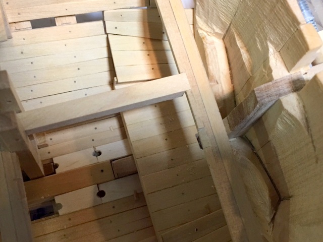
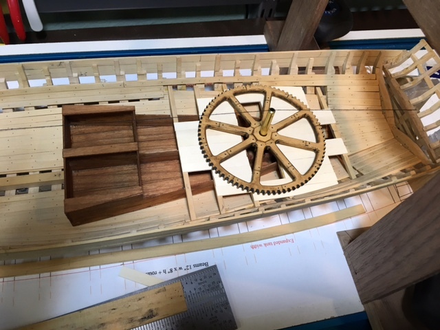
A bunch of little things. The fore and aft below-deck platforms are completed and set in place (not glued yet). The forward two sections of the water tank have been raised 15" since they do not interfere with the gear deck. They now go up almost to the bottom of the main deck beams and raise the capacity of the two sections by about 35%. The added pieces still need to be oiled. The gear deck beams and some planking have been laid down to check for clearance between the top of the gear and the bottom of the beams. Just fits with about 1.5" to spare. The capstans and partners will conceal some of the detail, but if Toni Levine can have a seaman lounging in hammocks on the lower deck of Atalanta, I can hide some work too. Careful alignment of the gear-deck beams so the axle of the rear (small gear) does not interfere will be next. Maury
- 525 replies
-
- 15
-
-
- anchor hoy
- hoy
- (and 1 more)
-
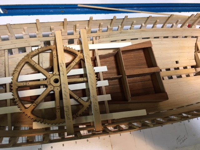
Per, The joints are arranged on each spoke at the intersection of the ajacent spokes and gear and about half-way between spokes on the gear head. The monofilament line idea comes from Ed Tosti's Naiad and Young America builds. I've used two different sizes, depending on application. They are dipped in CA, inserted, sliced off and wiped with acetone immediately. Roger, thanks again for the mill reference. Maury
- 525 replies
-
- 4
-
-
- anchor hoy
- hoy
- (and 1 more)