
HOLIDAY DONATION DRIVE - SUPPORT MSW - DO YOUR PART TO KEEP THIS GREAT FORUM GOING! (Only 20 donations so far - C'mon guys!)
×
Maury S
-
Posts
1,490 -
Joined
-
Last visited
Content Type
Profiles
Forums
Gallery
Events
Everything posted by Maury S
-
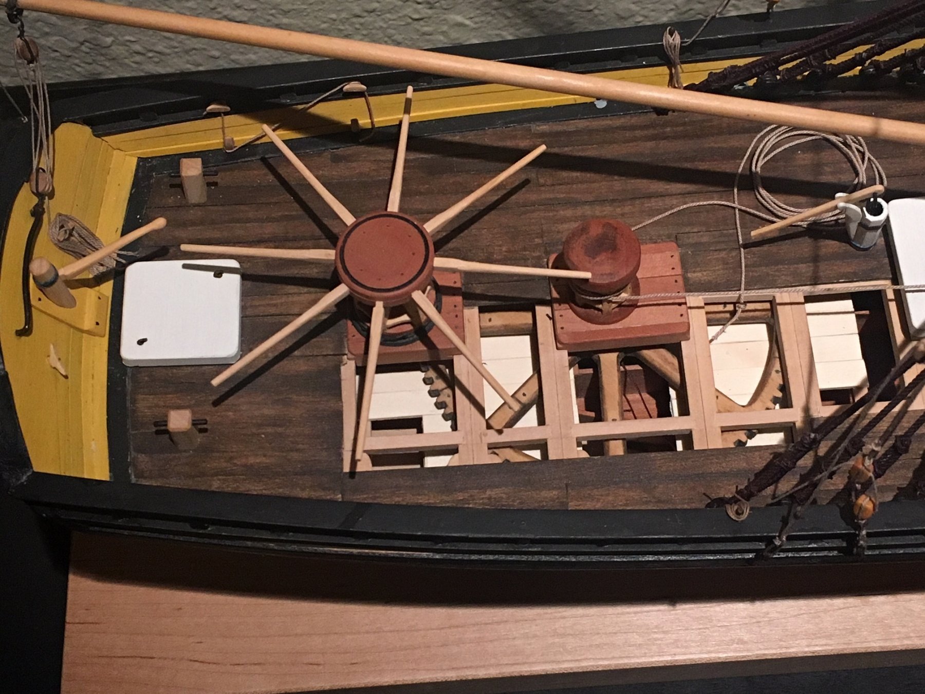
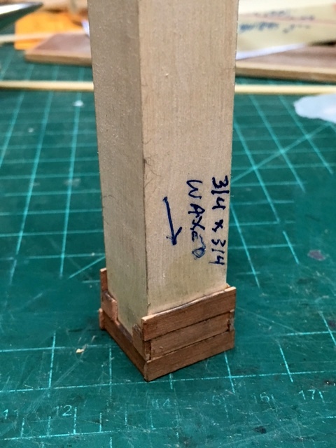
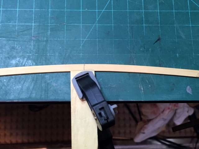
 Back to the outer planking. I need one more strake (bulwarks) to give the stern timbers added strength. Material was thicknessed to .0625" (the first layer of wales was .05" leaving a small ridge to butt the next layer of wales) and cut to a width of 10.5" (.22" actual), bent with a heating iron and form to get the bend at the bow. The pieces are approximately 30' long, making 3 pieces per side. There is some slight edge bending for the two aft-most pieces. Glued to the frames and held tight against the wales with parallel clamps. While glue was drying, I worked on the "waterproof" cabinet that surrounds the forward capstan axle, sitting in the middle of the water tank. The cabinet was formed around a 3/4" x 3/4" blank, waxed so the glue would not stick. The cabinet sits over the step for the axle. It is "cutaway" on one side for viewing. I like the way Dan Vadas did the cutaway on his section, marking the edges of the cutaway in red so there will be fewer questions on why the cabinet does not go all the way up. Maury

- 525 replies
-
- 10
-

-
- anchor hoy
- hoy
- (and 1 more)
-
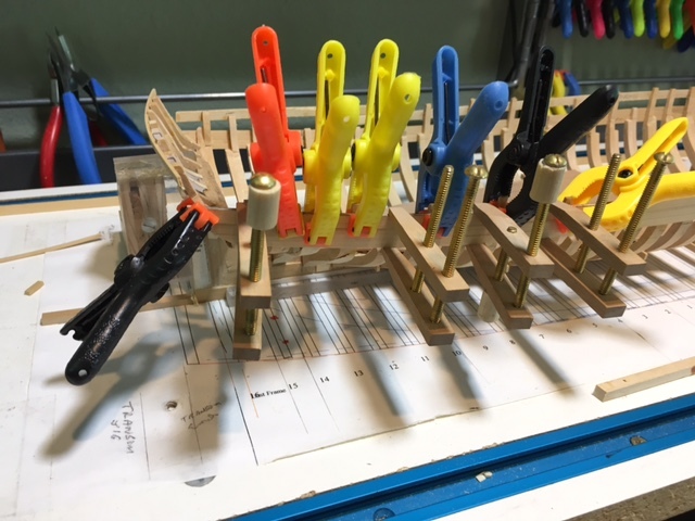
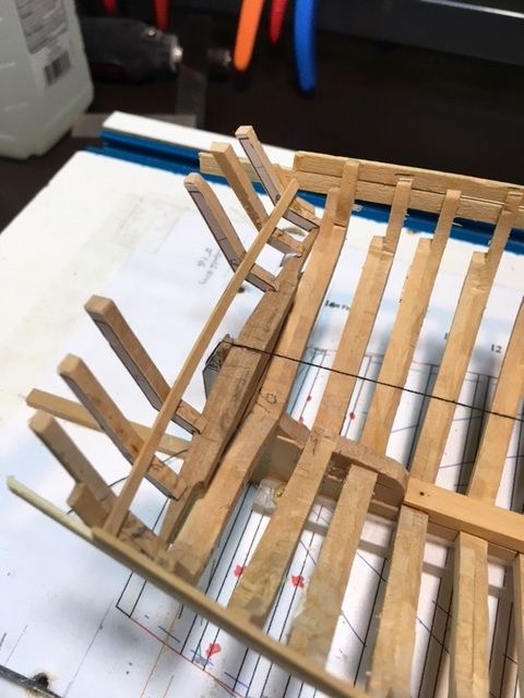
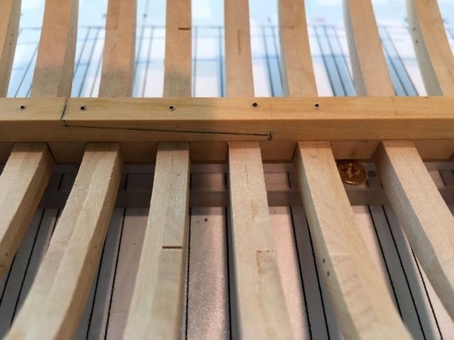
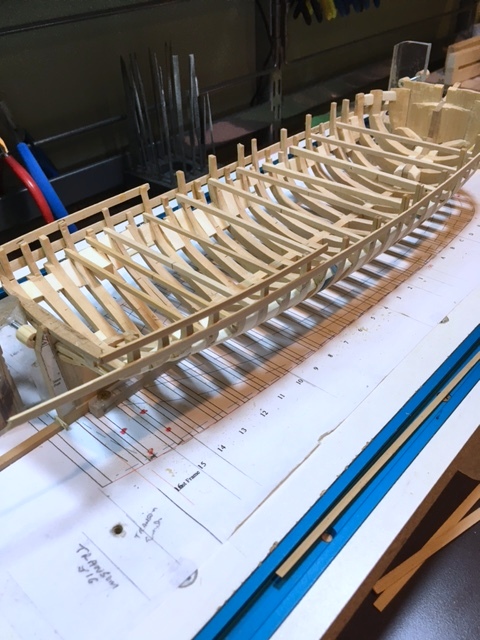
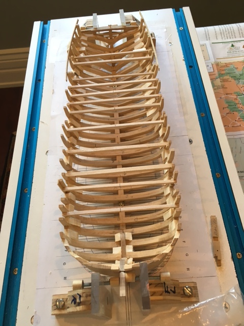
I've sanded the inner sides of the frames down to 220 grit. The bottom of the deck planking was measured from the profile at six frames and transferred to the inner edge of the relevant frames. A thin batten was clamped at each of the marks and examined for "fairness". Once satisfied, I marked all of the frames. This sets the bottom of the deck and the top of the deck beams. I'll make a pattern piece 8" deep to mark the bottom of the beams / top of clamp. Visible in the picture are the two wales and the temporary support batten on the outer side of the frames. The batten will be removed to add the bulwarks. Which brings up another issue. How do I remove the temp. batten without weakening the glue of the wales or other joints in the frames? At the NRG conference, a table mate was explaining how the folks at TiteBond told him to break the bond with heat. It seems to breakdown above 200 degrees. To test it out, I held my plank-bending iron against my #11 blade which was held in the glue joint. It doesn't work any faster than Iso, but with a little wiggling of the blade, the bond gives way. Be careful with the iron! Maury
- 525 replies
-
- 9
-
-
- anchor hoy
- hoy
- (and 1 more)
-
"Museum Glass" for the case is an alternative, but very expensive. I think it blocks out a lot and certainly eliminates glare. Providing some air holes for circulation is important as well. Maury
-
I was sanding the inner frames and half of the stern timbers got knocked off. Back to the jig holding them in place. I'll limit my sanding work to those times when the model is on the board and in the jig. A couple of bullwarks strakes and something more across all the stern timbers will add to the support. That involves laying out the planking above the wales, which in turn involves removing some of the temporary battens. Patience! Maury
- 525 replies
-
- 3
-
-
- anchor hoy
- hoy
- (and 1 more)
-
The two thin strakes of wales are in. I made the mast step and the steps for the two capstan axles. The step for the mast has a rectangular hole and the ones for the capstans are round for the diameter of the axles. There is nothing in the Grice drawings about the steps so I took some liberty. They are fit but not permanently attached. Maury

- 525 replies
-
- 12
-
-
- anchor hoy
- hoy
- (and 1 more)
-
The second wale strakes have been installed. Clamped to the frames and held tight against the first strake. Once the glue sets, I pull off the stern timber jig. Maury
- 525 replies
-
- 14
-
-
- anchor hoy
- hoy
- (and 1 more)
-
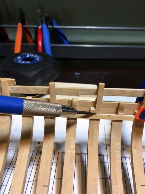
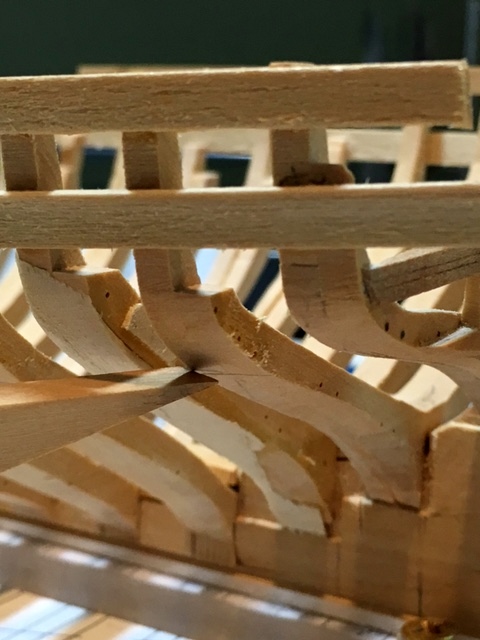
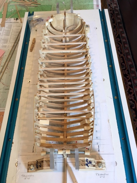
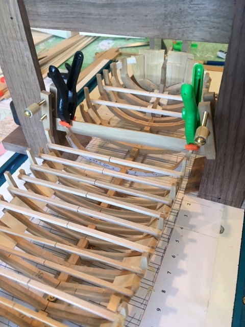
I needed to re-glue the stern frames. There is hardly anything to glue to and when I removed the Jig a couple came loose. The key is to hold them in the jig while the wales are being glued on. That meant cutting away some of the jig so I could get my fingers and clamps in there. I cut the jig back to just where the outermost timbers meet and I beveled the edge of the slots. Spacers were glued between the timbers to stiffen the section. See picture. The glue is drying on the first two wales now. After the second strakes are on, I'll pull off the jig, hopefully it will come off easily. Maury
- 525 replies
-
- 14
-
-
- anchor hoy
- hoy
- (and 1 more)
-
Looking way forward, I've been researching the lining of the water tank and the sheathing of the outer hull. Grimwood's American Ship Models, where the boat is featured in one section, says nothing about the tank lining but indicates the lower hull was sheathed with copper plates. I have doubts about that (copper bottom) for several reasons. Grice's drawings from the National Archives give no indication of any hull plating. Several sources, including an article in NRJ by Erik Ronnberg, Jr. back in 1980 (26; 3, 125 -148) about copper sheathing indicates how expensive it was. Since resistance to worms seems to have been a major reason for sheathing, coppering may not have been done if the worm was not prolific in New York or Philadelphia harbors. As it turns out Mr. Ronneberg's father built a model of the same boat in the 1950s. The photos of that model (see attached link) http://shipmodel.com/models/anchor-hoy-full-hull show "white stuff" below the waterline (artist's license?). As far as the tank lining, I've not found anything specific in articles about harbor craft, but tin was prevalent as was zinc alloyed over iron sheets. If anyone has any knowledge or a source reference, I'd appreciate the info. Maury
- 525 replies
-
- 3
-
-
- anchor hoy
- hoy
- (and 1 more)
-
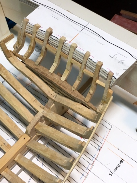
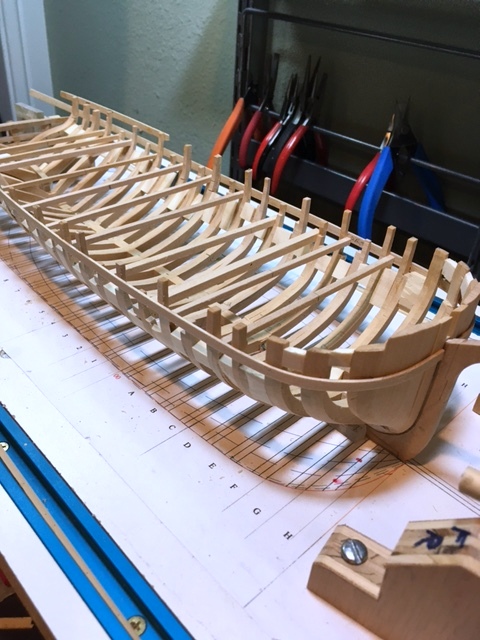
The stern timbers have been glued to the wing transom using the jig shown several posts back. The outer ones (which were doubled to get the fairing right) may need just a hair sanded off. I put a temporary batten across the inside for more support. The wales go on next, which will provide much more support. Maury
- 525 replies
-
- 16
-
-
- anchor hoy
- hoy
- (and 1 more)
-
One of the two temporary battens as been re-positioned higher. The "School Glue" I used on the battens took as much Iso and effort to remove as Titebond. Surprised. I thickness-sanded the material for the first layer of the wales to about .05+". It just seemed easier to bend than 1/16" stock. I'll build them up later in three layers since the bend at the bows is so severe. Maury
- 525 replies
-
- 2
-
-
- anchor hoy
- hoy
- (and 1 more)
-
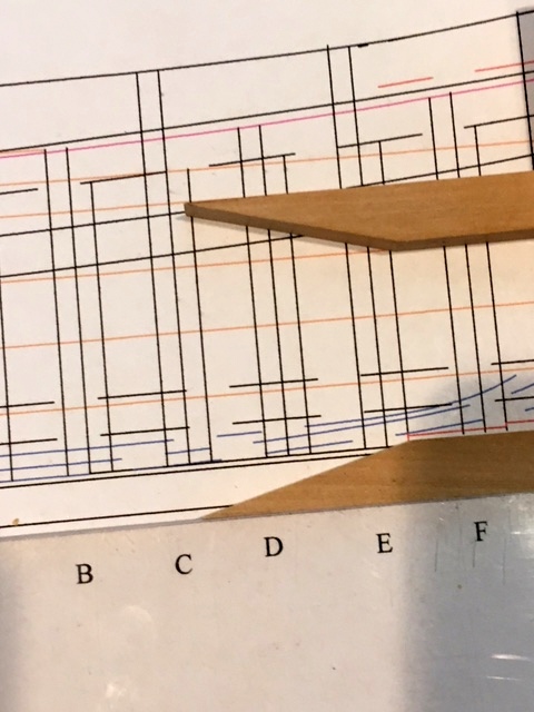
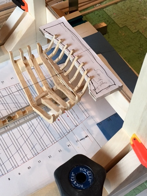
Putting the wales on means the stern timbers go on first. The wales provide support for these delicate parts. Marking the frames where the wale lies revealed a problem. The wale was drawn on the profile plan with information gathered from the original Greice drawings (those were not plans!). As I drew it, it lies under the turn of the hull near the stern so it would not provide the protection to the side of the boat. See first picture. I should have used the frame (half breadth) drawings to make sure the wale was at the outermost edge of the frame. As it turns out, the top of the wale as drawn on the profile (see pic. #2) is a good line for the bottom of the wale on the boat (at the widest point on the frames). I'm just going to raise it by that much. I may have to move the riband (temporary batten) out of the way a bit. Maury
- 525 replies
-
- 8
-
-
- anchor hoy
- hoy
- (and 1 more)
-
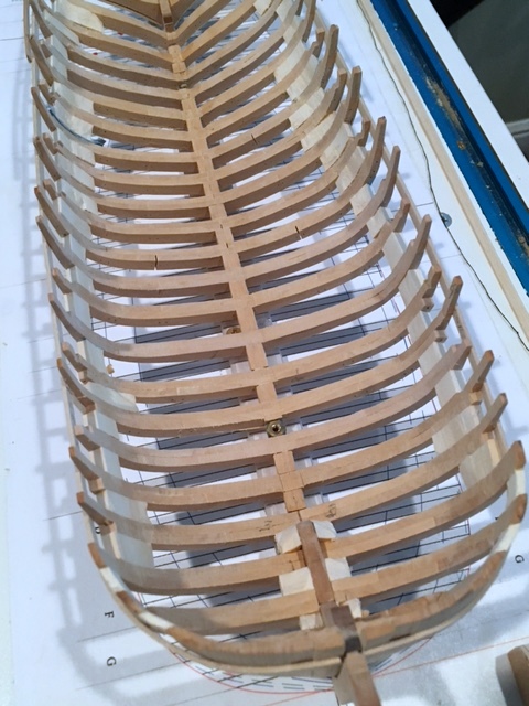
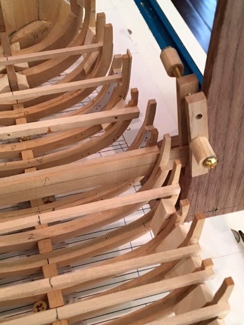
The spacers are removed and the keelson is glued in place. The gantry and "square frames" on the building board come in handy by providing a method to hold down the keelson while the glue dries. Another once-over with 220 grit sanding on the outside of the frames and I'll be ready to layout the wales. Maury
- 525 replies
-
- 11
-
-
- anchor hoy
- hoy
- (and 1 more)
-
Ed, Thanks for the tip. Looking closely, the spacers are right where the deck clamps and the wales go. The spacers will be pulled out over the next few days. I got tired of sanding so I built the keelson (not permanently installed yet). The bolts, positioned at every other frame and near the ends of the joint, are simulated using 25 pound black monofilament line (#73 drill bit) and fixed in place with a dab of CA, wiped off with acetone. Maury
- 525 replies
-
- 14
-
-
- anchor hoy
- hoy
- (and 1 more)
-
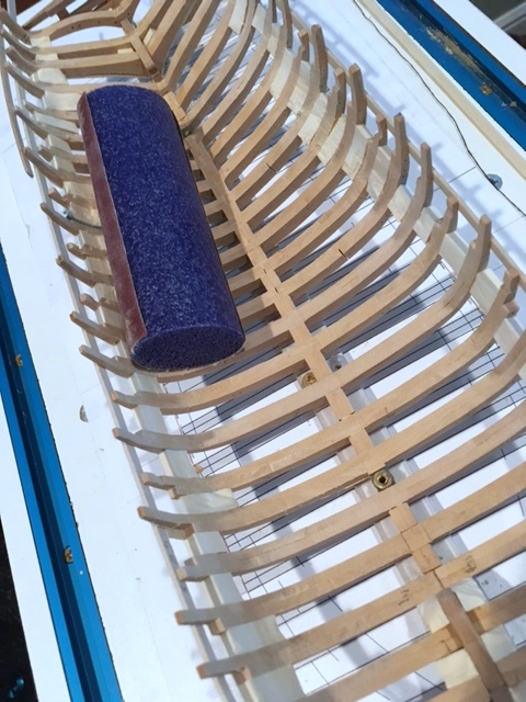
Most of the rough interior sanding is done. I like the "SuperFlex" sanding blocks. They are medium-firm foam plastic in a variety of shapes. I think I picked up the pack at Harbor Freight. I would never buy any serious tool there, but clamps and sanding blocks are fine. I have to check the thickness of the tops of the frames to make sure they match side to side and confirm they are "fair", then the keelson goes in. The spacer blocks need to come out and there needs to be more longitudinal support in the form of deck clamps or wales. Not sure which would be better first. Maury
- 525 replies
-
- 14
-
-
- anchor hoy
- hoy
- (and 1 more)
-
thanks for the likes and comments. If I seem to be missing a step, please chime in. The bluff bow will indeed be a challenge. I will be planking both sides up to a point. I want to show the details of the seating of the "great cat", the water tank and the gearing for the two compound capstans. I'm not sure just yet as to which planking to omit...some where between leaving one side unplanked and the "windows" EdTosti is doing on Young America. Maury
- 525 replies
-
- 3
-
-
- anchor hoy
- hoy
- (and 1 more)
-
The frame adjustments have been made and the fairing is complete (grits 80, 100, 150 and 220). Everything seems good so I put on the two full-length temporary battens using Elmers school glue so it will be easier to remove later on (I think). The next step seems to be to remove the horizontal frame braces so I can get to the inside of the frames. I'm going to leave the pine spacers in place to provide more support while sanding the inside. That means extra chiseling and sanding on the spacers, but I think the support they provide is more important. Maury
- 525 replies
-
- 10
-
-
- anchor hoy
- hoy
- (and 1 more)
-
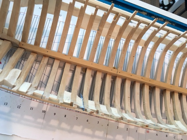
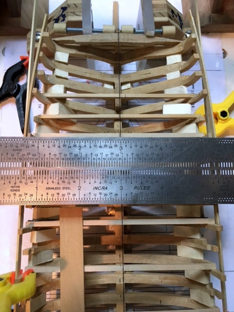
I used a temporary batten to check the rough fairing so far...looking for high or low spots at the tops of frames. I checked the distance from center-line to the outer edge of each top. Two frames needed building up and several sanding down. Black thread seems off-center in the photo, but it's the camera angle. Maury
- 525 replies
-
- 8
-
-
- anchor hoy
- hoy
- (and 1 more)
-
Back from vacation, so the weekend will be spent sharpening chisels, replacing sandpaper on sanding sticks and pads, cleaning up here and there and getting set to fairing both inside and outside of the frames. It's messy work so I'll be in the garage where sawdust is always present. Temperatures have dropped a whole bunch so it's tolerable there. Maury
- 525 replies
-
- 3
-
-
- anchor hoy
- hoy
- (and 1 more)
-
Clearly you're going to make the chains link by link. Maury
- 3,618 replies
-
- 4
-
-
- young america
- clipper
- (and 1 more)
-
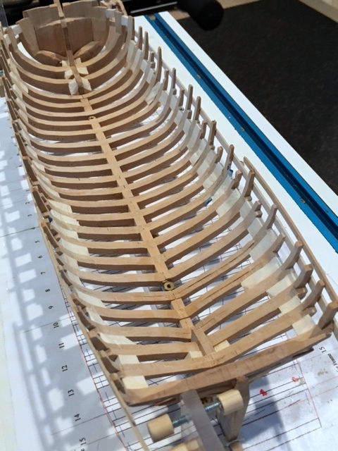
All the frames are now in place. A lot of fairing to do, and a couple of low spots that need to be built up a wee bit. The temporary battens over the aft-most 8 frames are protecting those delicate tops really well. There are a few frames where the tops parts of the frames are small...not much overlap with the paired frame parts. Next time, those will be longer. Once planking starts, they will not be an issue. After fairing both sides I'll install at least one strake of planking (probably the wale) and that will give everything a lot of support. Off to make some more sawdust. Maury
- 525 replies
-
- 9
-
-
- anchor hoy
- hoy
- (and 1 more)
-
The new supply of timber arrived so I remade the four frames that were out of wack. Everything seems to line up better. We'll see once I finish the temporary blocking between frames and take it off the board. When I removed some of those temporary blocks, I had quite a time with the Iso. For the new blocks, I'm using white school glue. I assume it's not as strong as the TiteBond II, and wont be as tough to remove later. Two more pictures of the gantry being used to attach and level the frames where the building board square frames will not fit. Maury

- 525 replies
-
- 12
-
-
- anchor hoy
- hoy
- (and 1 more)
-
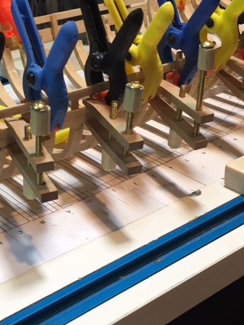
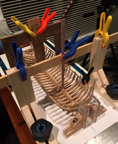
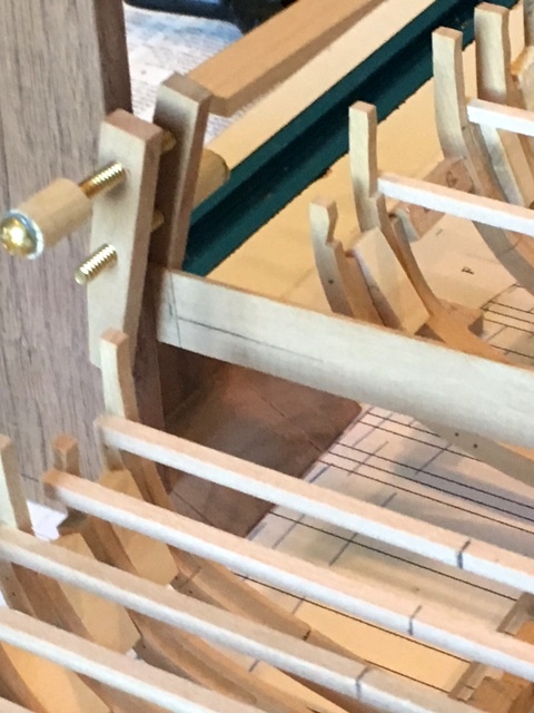
Good progress on installing additional frames. The stern timbers have been removed to prevent damage. I have run out of 1/8" material to finish up the remaining three revised frames (C, Dead Flat-00 and #2 ). Even so, I can proceed. I've installed all the frames (moving both fore and aft) until I reached the point where the "square building board frames" no longer fit between the existing ship frames. Time for the gantry (thanks again to Ed Tosti). First I clamped a piece of scrap (1/16") wood spanning the sides of the gantry and marked the height of the frame at deck level just as I had marked the "square bldg. bd frames." I then lined up the measuring points on the gantry with the body plan on the building board and set the frame in place using the marks on the scrap to keep the frame level and plumb. The colored clamps are holding the frame tops secure while the glue dries. This arrangement will allow me to work between existing frames once I get more timber. I should be able to get a pretty fair line along the tops even with those three frames missing. Once I fair the sides of the tops of the frames I can install some temporary battens to stiffen everything and secure the stern timbers. I'm thinking just gluing on the battens will be strong enough unless someone has a warning and convinces me to pin them as well. Maury
- 525 replies
-
- 13
-
-
- anchor hoy
- hoy
- (and 1 more)
-
I cut out all the stern timbers and left the tops a little long for final trimming (there is a nice arch in the original drawing). I need the outer-most stern timbers in place to properly fair the last few frames. A lot of meat needs to be trimmed off the last frame (16). Maybe some temporary battens across the back and along the side will help. I guess I can install the mid-ship frames first and get the battens set. I think I'll pre-fair the aft edges of the stern timbers a bit 'cause there is no way they will stand up to sanding without a lot of support. Maury
- 525 replies
-
- 10
-
-
- anchor hoy
- hoy
- (and 1 more)