
HOLIDAY DONATION DRIVE - SUPPORT MSW - DO YOUR PART TO KEEP THIS GREAT FORUM GOING! (Only 20 donations so far - C'mon guys!)
×
Maury S
-
Posts
1,490 -
Joined
-
Last visited
Content Type
Profiles
Forums
Gallery
Events
Everything posted by Maury S
-
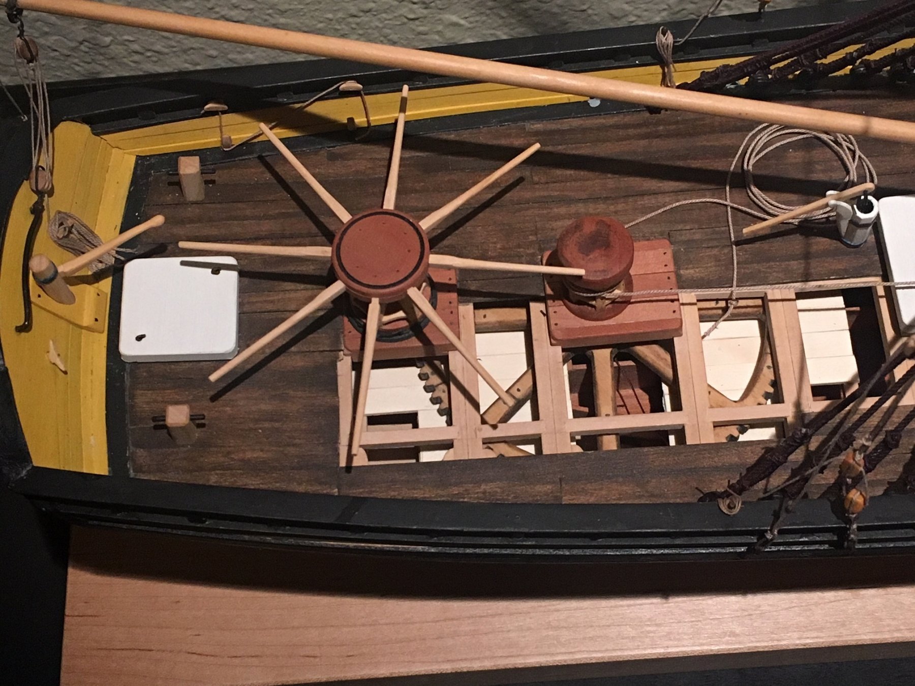
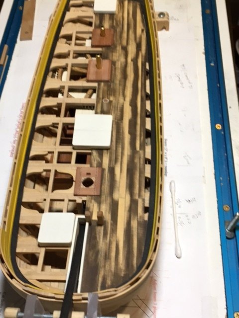
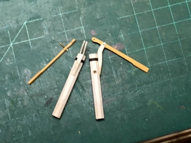
 A bunch of progress over the weekend. The deck planking was extended to the center-line, then scraped even. It's surprising how much variation in installed planks there was even though they were all thicknessed at once. I built up the Elm Tree Pumps...standard design from either Echo or Cheerful plans. One of the arms needs some straightening out a bit. Once the handle is in, it will hold just fine. The pump tubes are <1' (octagonal) (<1/4") and stand about 3.5' above the deck. Not shown are the exit tubes (3/32" brass tubing) or the plunger rod. Reinforcing bands are black paper painted "Iron Black". The handles will be shortened a bit. Maury
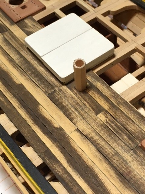
- 525 replies
-
- 15
-

-
- anchor hoy
- hoy
- (and 1 more)
-
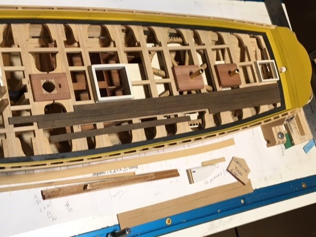
I started the deck planking. I experimented with holly and box. The holly was too soft and the finish came out blotchy. First task was several tests of color and tone. Planks were cut to 2.5" x 10" (full size) on the saw and thickness sander and then treated with a Model Shipways black walnut stain (water based). Two coats was enough for now. The first plank next to the main hatch was the starting point. Both ends were set equidistant from the center line and abutted to the hatch. Planks will be parallel out to the side. Tapering will be done on the final strake(s). Following the planking plan for where joints fall, I started moving out towards the sides. The edges of the planks are rubbed with a soft pencil to simulate caulking. The starboard side will have sections left off for exposure of the gears, water tank and great cat. An advantage of me making all the beams paired from two 6x pieces is I have a center point on each beam for landing joints. I'm experimenting with simulated plugs rather than treenails for the deck planks. The plugs will be tapped in once decking is complete. I'm using thin hypodermic tubing to make the outline of the plug. Highlighting will be done with either black leather polish or India ink. Subtle, but not too much so. Maury
- 525 replies
-
- 14
-
-
- anchor hoy
- hoy
- (and 1 more)
-
Gaetan, So you went to your dentist and instead of asking for an old scraper or pick, you asked for a chair? Wow. "If you don't ask, you don't get." Maury
-
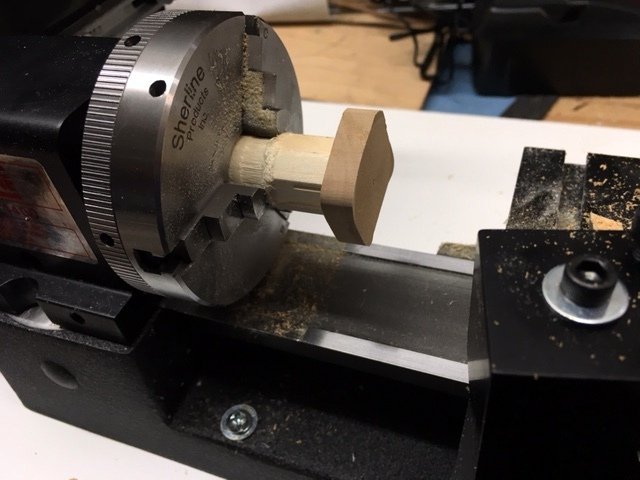
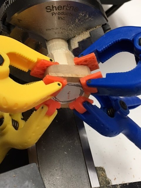
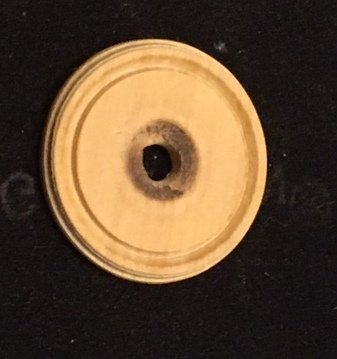
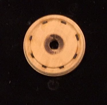
I got to tryout my Sherline lathe on serious work for the first time. There is pawl ring under the capstans. It is round. First hint the lathe may be the right tool. The object was to cut a ring with a channel in it. Since the capstan covers it the inner portion does not matter. First I built a carrier jig to hold the piece I'll be working on. It's just a piece of flat 1/4" stock glued to the end of a dowel. It will be reusable for the other ring and maybe something else. I faced it on the lathe to make sure the final piece would not vary in thickness and left it in the chuck. Then I glued the pattern (approximately) in the center and temporarily tacked and clamped the working piece (1/16" board) to the jig and let it dry overnight. I blew the first attempt. I ended up with a chip in the outer portion of the ring. (no picture). Higher speed and slower feed corrected the problem on the second try. The inner section will be covered by the capstan so the finish does not matter. Big improvement. It took me twice as much time soaking in iso. and prying it off the jig as it took to set up and cut. Next come the pawl stops in the channel. 25 Lb. monofilament line cut into little pieces and (CA) glued in place. Now it all gets painted "iron black" so it looks like metal and a lot of the detail disappears. Maury
- 525 replies
-
- 12
-
-
- anchor hoy
- hoy
- (and 1 more)
-
Ed, AMAZING. BTW, why would they use a chain (even canvas covered) to hold down the lifeboats? Maury
- 3,618 replies
-
- 4
-
-
- young america
- clipper
- (and 1 more)
-
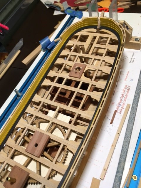
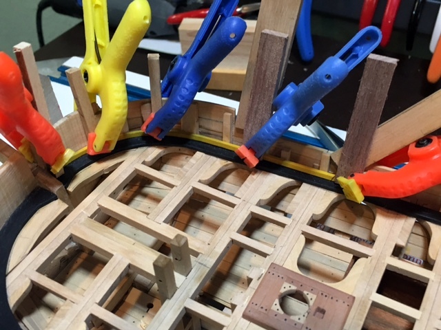
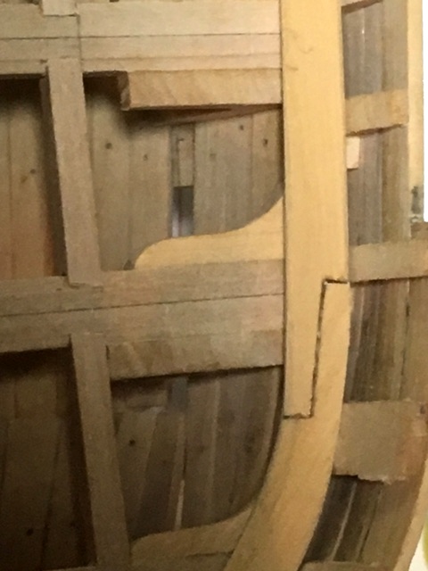
The inner bulwarks are done. The partners are not yet glued in place. I've faired the tops of the inner and outer bulwarks for the main rail. Not sure whether I put in the deck planking before the rails. The bow and transom have arched rails so some serious bending is yet to be done. Maury
- 525 replies
-
- 21
-
-
- anchor hoy
- hoy
- (and 1 more)
-
Source is American Ship Models...V.R. Grimwood 1942 Plate III, reproduced in NRG : Shipyard and Service Craft, Part I Robert Cairo...circa 1970s. Maury
- 525 replies
-
- 2
-
-
- anchor hoy
- hoy
- (and 1 more)
-
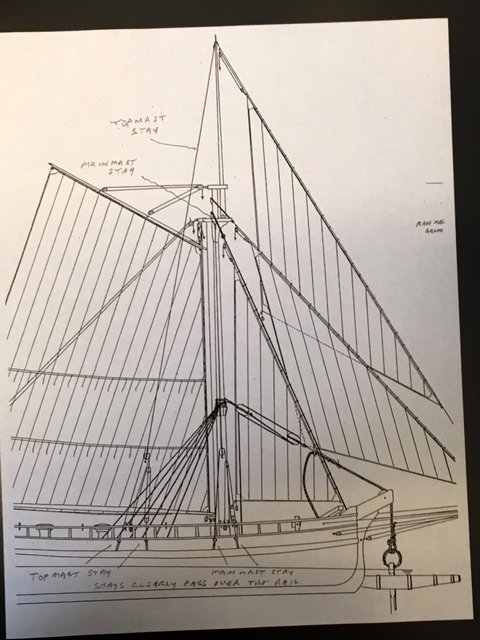
Planning ahead...The Rigging Plan (source: Robt. Cairo plan from NRG series), while fairly complete, presents some challenges. The main shrouds are designed to support the mast where the rigging for the great cat attaches (20' above the deck). There are no other shrouds shown. The fore stays (3) are standard. There is a "running back stay" for both the main and top masts. Halyards, lifts, sheets, etc. are standard. Questions arise. The main shrouds attach inboard at the waterways. They limit the range of the main boom to about 20 degrees from center. Would they have been removed while sailing? Hard to run or broad reach as rigged. The running stays seem grossly inadequate to support the rig. They attach to the bulwarks with chain plates and pass over the edge of the top rail where they would bind (no tumblehome on this boat). There has to be enough off-set to clear the rail so I assume channels need to be installed though not shown on any drawing nor do they appear on the only serious model (Erik Ronnberg) I've seen. Comments welcomed! Maury
- 525 replies
-
- 5
-
-
- anchor hoy
- hoy
- (and 1 more)
-
Couple questions of Sherline Mill purchase
Maury S replied to sfotinos's topic in Modeling tools and Workshop Equipment
I bought mine after the NRG conference direct from Sherline and got a 10% Conference discount. THey had a "Senior Citizen" 10% discount as well but not both. Maury -
There is a great deal of info. photos, etc. on granite sloops. Very active from Maine down to NY and DC. Many are center boarders which you rarely find on this forum. I spent some time looking at the Albert Baldwin before choosing the Anchor Hoy. It was just too big a boat for me to do in 1:48 scale. Maury
-
Model Shipway's Paints
Maury S replied to Worldway's topic in Painting, finishing and weathering products and techniques
You can get a "universal Acrylic thinner" at Hobby Lobby and elsewhere. It's worth trying to bring them back. Maury -
I'm not able to work on the model this week, so I'm creating the deck planking plan in TurboCAD. I made sure the outline of the deck matched the drawing . Then I adjusted the hatch openings and partners on the plan to match what I've made (very little variation). Next is to measure each side from center line to the waterways (one side is about 2" wider than the other). I chose 10" planks for the deck, and there is 100" width at dead flat on the port side and 102" on starboard. The main hatch is the widest item along the center line. It is 60" wide so six planks at ten inches will be carried all the way fore and aft. Seven more 10" planks fit between the edge of the hatch coaming and the waterway on port. The exposed areas will all be on the starboard side so having a few planks at 10.2" won't be a big issue. Since butt spacing will not be an issue between the hatches and partners, I started from the hatch coaming and worked outward with the following guidelines for the butts: Twenty foot maximum + / - plank length. All joints land on a beam. No butt joints at the corners of the hatches and partners. Two planks between a joint on a beam. Two beams between joints on adjacent planks. No planks shorter than a span of three beams. (except the six down the center line between the mast partners and the main hatch). So much for theory and it's a good thing these are guidelines and not RULES. After hours of shifting butts around the last version has: two planks about 24' long, no butts at the corners of the hatches and partners (there are 4 - 6 planks terminating at those areas and it seems strength would allow no more at those points), Two planks between butts on a beam works for the area between the main hatch and the fore capstan then everything breaks down when I apply the other guidelines on adjacent beams. Either there is a joint at the corner of the hatch / partner or there is only one beam between butts on adjacent planks or the plank is too long or too short. The diagram pasted into MS Paint is too small to see so no picture. I have to prioritize. I think two planks between joints on one beam is more important than two beams between joints on a plank. Narrowing the plank width creates more complications. Maury
- 525 replies
-
- 2
-
-
- anchor hoy
- hoy
- (and 1 more)
-
A cyclone system works quite well. I have one hooked up to my Byrnes Sander and have not had to change a vac. filter since. Maury
-
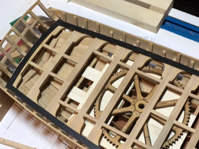
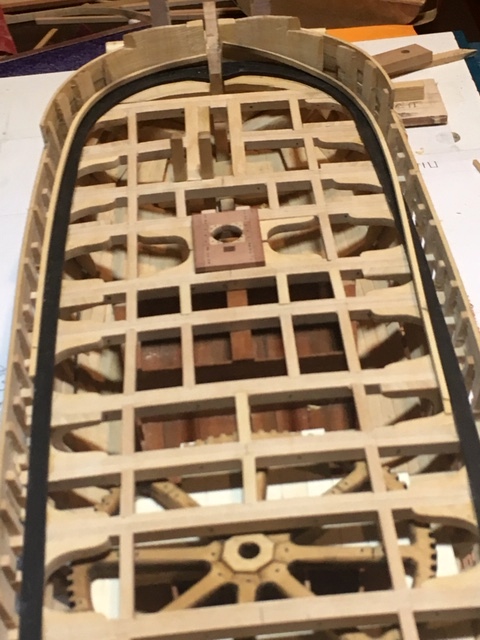
I reviewed the Rudder Stock Geometry posts and found the string interesting. I was not familiar with the "plugstock rudder" term. There is an off-set as the stock passes thru the counter and then goes vertical again. I've built up the rudder and have a hole in the inner transom bulwarks just larger than the stock. I'll adjust it as I proceed. I imagine this area was lined. I will probably put in a block. The transom planks have been partially extended up as the bulwarks along the side butt up against them. See the second picture below with the first of two strakes installed above the spirketing. Boy, the lens sure shows things I can not see. Four coats of paint may not be enough. Maury

- 525 replies
-
- 9
-
-
- anchor hoy
- hoy
- (and 1 more)
-
Ed, You've probably mentioned it before, but how much dilution to the tung oil, and with what? Maury
- 3,618 replies
-
- 4
-
-
- young america
- clipper
- (and 1 more)
-
And I've used that brake on several occasions. (I used to race sailboats) Maury
- 525 replies
-
- 2
-
-
- anchor hoy
- hoy
- (and 1 more)
-
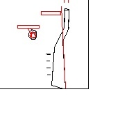
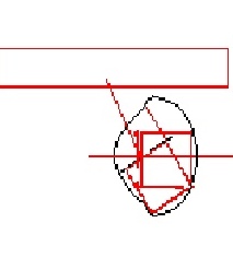
Thanks for all the comments and "likes". Because of the shape of the rudder post and the axis of rotation, the hole through the transom is different than the keystone shaped hole most of us are familiar with (sic). It's more of a rugby ball shape. A bit of geometry, rotating the post in CAD came up with the rough shape. Text boxes are empty...refer to the center of rotation. Hole picture exploded about 4x. Maury
- 525 replies
-
- 3
-
-
- anchor hoy
- hoy
- (and 1 more)
-
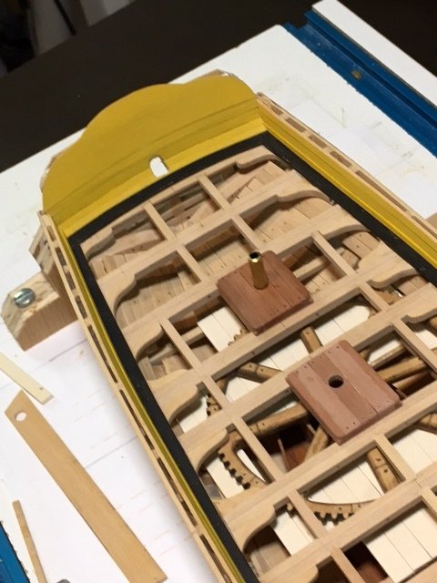
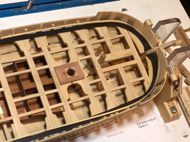
The spirketing is being installed. The spirketing piece is held down on the waterway and against the frame with braces that are notched and clamped to the bulwarks. The notches will be lengthened when I get ready to install the inner bulwark planking (? thin stuff ?). I had to make up a dummy rudder to make sure the planking on the transom will not inhibit the turning of the rudder. I'll shape the hole as I move up with the transom planks. Maury
- 525 replies
-
- 10
-
-
- anchor hoy
- hoy
- (and 1 more)
-
Mike, it looks great. BTW, shouldn't the hook open side be facing upward? Just kidding! Maury
- 452 replies
-
- 3
-
-
- cheerful
- Syren Ship Model Company
- (and 1 more)
-
Echo by davec - FINISHED - cross-section
Maury S replied to davec's topic in - Build logs for subjects built 1751 - 1800
Dave, I like the shift from Box to holly at the waterline...Was the waterline really that high up on the Echo? Nice wales! Maury -
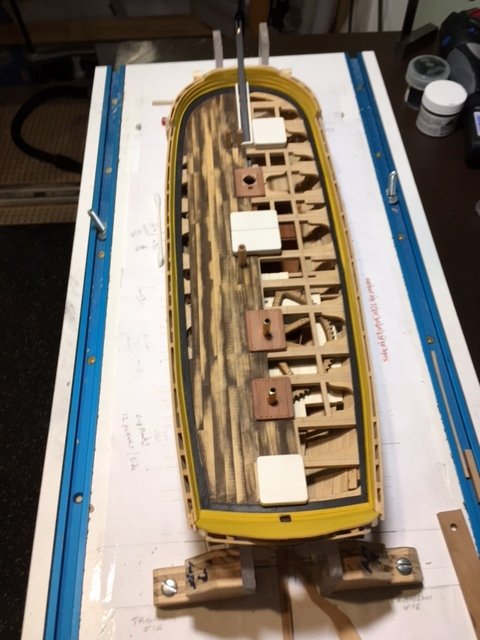
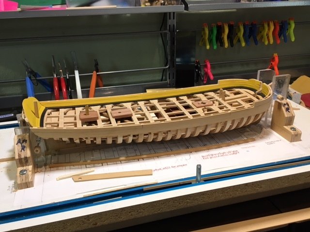
Waterways installed. I cut and shaped the forward spirketing seen in the first and third pics. just laying in place. I'm going to paint the spirketing before installing. Maury
- 525 replies
-
- 15
-
-
- anchor hoy
- hoy
- (and 1 more)
-
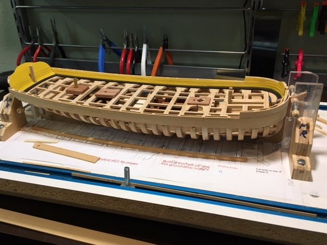
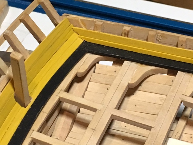
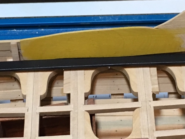
The waterways are now painted and there is no sign of the joints. Actually, if you look with a magnifying glass you can make them out. I mixed paint for the "yellow ocher" that the description calls for. That color from Model Shipways is WAY TOO Brown. This test sample is about 50 - 60% "pure yellow" mixed with the MS paint. Four or five thinned down coats on boxwood. Photo is a bit brighter than real life. Second mate calls this "mustard" and says "it's not a pretty color". Pretty is definitely not what I was looking for. I think it's just what I wanted. Once the waterways have dried for a few more hours, I'll install them on the boat and start on the spirketing. Maury
- 525 replies
-
- 8
-
-
- anchor hoy
- hoy
- (and 1 more)
-
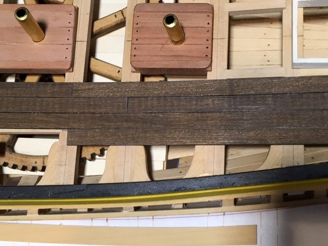
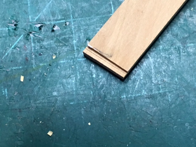
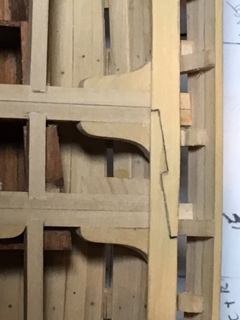
Waterway set in place. Both the hooked Scarf and a lap joint visible. Now for the other side. Maury
- 525 replies
-
- 12
-
-
- anchor hoy
- hoy
- (and 1 more)