Maury S
-
Posts
1,490 -
Joined
-
Last visited
Content Type
Profiles
Forums
Gallery
Events
Everything posted by Maury S
-
 I made a card template of the transom frame and it was very close to a good fit. A little tweaking of the wood pieces (slight angles where the frame meets the wing transom) and the eight pieces will be ready to install. There is hardly any support until some battens get put on, so I'm not going to install for some time. If someone has an idea of how to protect them, let me know. Maury
- 525 replies
-
- 10
-

-
- anchor hoy
- hoy
- (and 1 more)
-
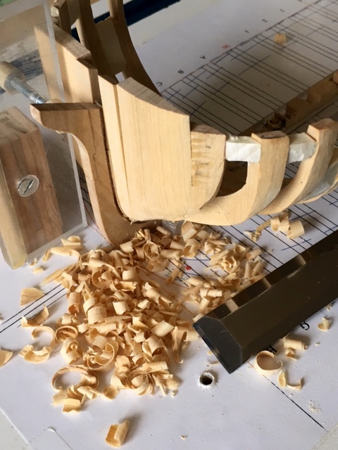
I had some time to add the remaining hawse timbers (fillers...I started with a piece of 0.20" x 1.125" piece of scrap) and roughed them out both inside and out. I'm not erecting several pieces on each side as was most likely done, but it's all going to be planked at the bow and I need the strength to withstand the severe fairing that will be needed.) Most of the paring was done with a 3/4" chisel on the outside and 3/8" chisel on the inside. Since I don't have my sharpener with me so I can't touch up the edges of the chisels and after a day's work, they will need it. (I didn't count how many times David Antscherl told me to sharpen my pencil and my chisels but it was a lot). Maybe I'll work on the transom. The frames are delicate and unprotected, so I don't think I'll go as far as gluing them in, but there's a lot to do to get them set properly. Maury
- 525 replies
-
- 11
-
-
- anchor hoy
- hoy
- (and 1 more)
-
Thanks for all the likes. When someone spots a potential issue, please speak up. I've got a long way to go in developing my skill levels and would never be this far without the generous guidance of so many on this forum. Frame 13 is the first full frame. It took some blocking and sanding to get it to the correct height. The deck line is more precise so the height is measured from the profile and transferred to the building board square frames. I marked a line on the edge of the frame exactly at the level of the deck. You can see where the temporary cross beam rests on the frame at this level. The frame (13) is then aligned on both sides and glued in place. It may become difficult to distinguish one line from another on the square frame so I'll probably use a fresh piece of tape on the edge for each subsequent frame. Erasing from the wood isn't enough. I've now arrived at the point of fairing the insides of the fore and aft-most frames while there is room to maneuver. Maury
- 525 replies
-
- 6
-
-
- anchor hoy
- hoy
- (and 1 more)
-
"I hope you are right about folks being interested. Its always a nerve racking experience to spend the time and money developing something like this with the hope folks will want it afterwards. " Chuck, Frustrations of an entrepreneur, but you are doing what you love and are much appreciated by all. Maury
- 269 replies
-
- 8
-
-
- Queen Anne Barge
- Syren Ship Model Company
- (and 1 more)
-
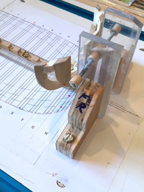
Half frame 14 being installed on the starboard side. Appropriate sized spacers are installed along frame 15. The Building board square frame is marked at the height (of the deck) and set square to the keel and aligned with the body plan frame line. The frame piece is glued up and held firmly to the deadwood and slid up / down until the marks on the frame line up with the mark on the square. The machinist squares are weighted and are holding the frame firmly against the spacers while the glue dries. The scrap of wood clamped to the building square is holding the bottom of the frame tightly against the deadwood. Once dry, I'll repeat the process on the port side. Maury
- 525 replies
-
- 7
-
-
- anchor hoy
- hoy
- (and 1 more)
-
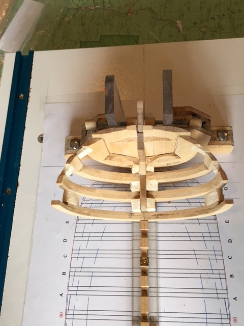
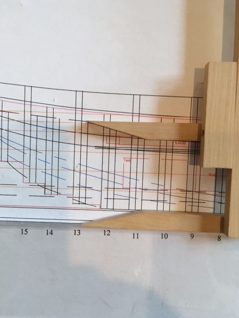
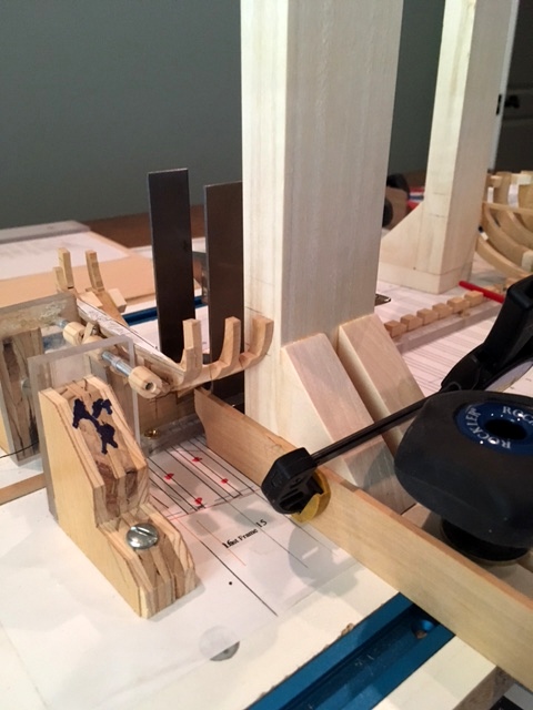
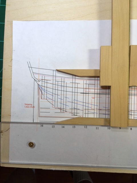
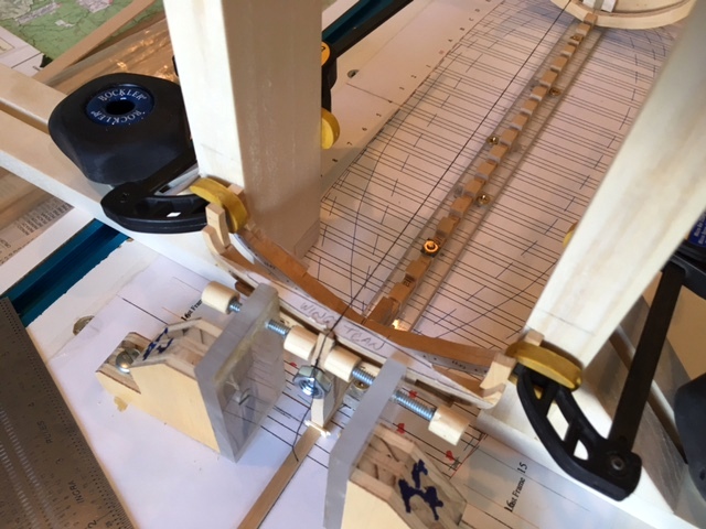
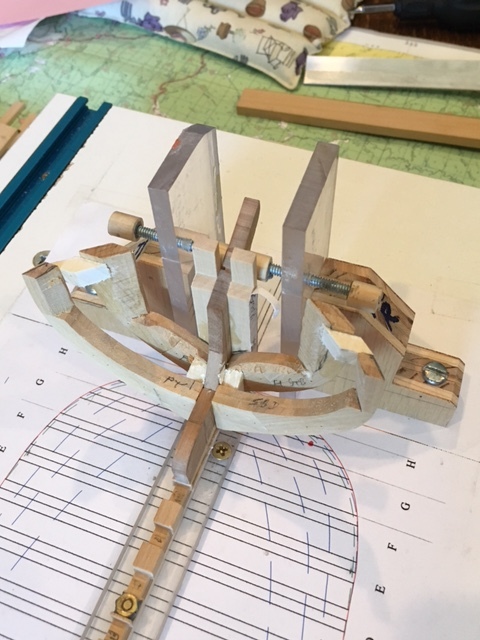
Frame 15 setup: 15 is the second frame from the stern (first is attached to the wing transom). First it is squared up to make sure is is centered athwart ships (now I'm sounding like Druxey) and the tops are at equal heights. The bottom of the frame straddles the deadwood resting on the steps built up on the deadwood) and the tops are measured from the profile plan (1st pic). That height is transferred to the edge of the two square building board adjustable frames (NOT the pencil marks about an inch above the tops in pic. #2). Those frames are set square to the keel and aligned with the body plan on the building board. The tops of frame 15 are set so they align with the marks on the building square. I have to cut some filler pieces to fit between frames 16 and 15 and then glue it up. There is no end to the effectiveness of Ed Tosti's tools and jigs. Maury
- 525 replies
-
- 8
-
-
- anchor hoy
- hoy
- (and 1 more)
-
There is going to be a lot of fairing of the bows before I call it a win, but watching how Chuck manages with POB models, I've gained some confidence. Frankly, the model, locked onto the building board seems quite sturdy. OK for inside fairing, but until that's done I'm not even going to think about the outside fairing. Thanks for all the "Likes" and especially the helpful comments. Maury
- 525 replies
-
- 2
-
-
- anchor hoy
- hoy
- (and 1 more)
-
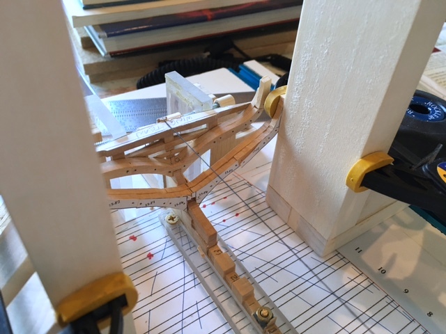
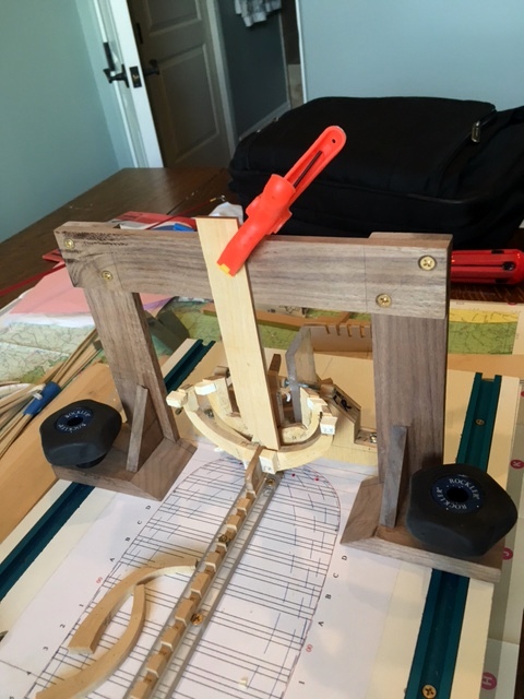
Frames G & H installed. Everything lines up with the body plan. Oops! The starboard half of Frame G crept up during the gluing. Iso to the rescue. I removed the frame, let it dry out from the alcohol and reset it. This time I used the gantry to create a hold-down jig (pic 3) while the glue set. Next half Frame F then on to the half frames at the stern. Maury
- 525 replies
-
- 8
-
-
- anchor hoy
- hoy
- (and 1 more)
-
Spacers between frames: I cut some carefully measured pine spacers to place at the bottom and near the top between Frames H and G. The fore sides of the second frame (G) will line up perfectly with the body plan on the building board and be consistent bottom to top. The Mini "Jorgensen-type" clamps (thx to Ed Tosti) are so much better than the spring clamps in circumstances like this. The spacers near the top will be removed much later. The ones along the keel assembly maybe cut even with the frames...or not. Original boats of the era would probably have had fillers between frames at the rising wood to prevent water accumulating between frames. Maury
- 525 replies
-
- 10
-
-
- anchor hoy
- hoy
- (and 1 more)
-
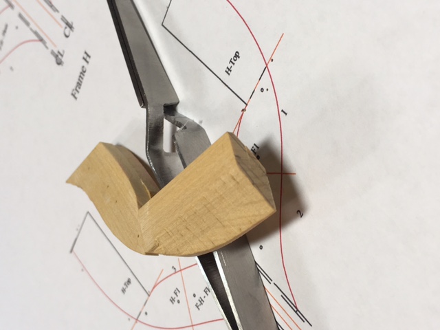
About a third of the frames needed re-lofting. The fore-most frames (H & G) especially needed thickening because of the sharp angle (Buff bow) and I had to leave plenty of meat on the piece. I roughly trimmed the tops of Frame H in preparation of attaching to the stem wood and the aft edge of the hawse pieces. Most of the next week or so will be dedicated to the fore and aft-most half frames. Once they are set, I can roughly fair the insides. Carefully measuring the thickness of the stem wood where the frames rest made alignment to the body plan right on (at least for Frame H). Maury

- 525 replies
-
- 8
-
-
- anchor hoy
- hoy
- (and 1 more)
-
Siggi, Very nice. Great presentation. Would you expand on how you did the "water". Plastic or glass? Maury
- 58 replies
-
- 3
-
-
- barge
- ships boat
- (and 1 more)
-
really nice. As close to POF as anyone is ever going to get. Maury
- 269 replies
-
- 2
-
-
- Queen Anne Barge
- Syren Ship Model Company
- (and 1 more)
-
I love the technology of the bending station! Maury
- 269 replies
-
- 3
-
-
- Queen Anne Barge
- Syren Ship Model Company
- (and 1 more)
-
I've been assembling the pieces for each frame. The last few have been with the control pin method and it's working OK. Not every hole lines up, but enough to get the pieces aligned and glued. Frames H and 12 - 15 needed re-lofting to match up with the plan width...The others look to line up well on the keel assembly. I need to spend time on the intersection of the bottom of each frame with the rabbet. One frame at a time. Then back to re-doing the 6 frames once my new scroll saw arrives. Maury
- 525 replies
-
- 4
-
-
- anchor hoy
- hoy
- (and 1 more)
-
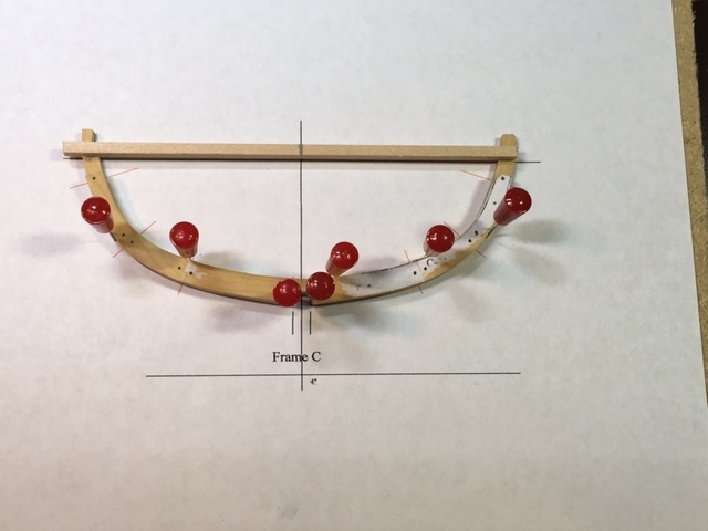
Taking Druxey's kind admonition, I am going back over all the completed frames. The actual height of each frame is not critical at this stage...it will be faired later. In TurboCad, I created a vertical line through the center of the frame (CL) and a horizontal line near the top of the frame where there is a ledge. Lining these points on the master frame plan, holding the frame on the plan and attaching (light dab of glue) a horizontal beam with a score on the top and edge at dead center not only gives temporary strength to the frame, it will help align everything once it goes on the keel. The horizontals will be removed later on. Maury
- 525 replies
-
- 12
-
-
- anchor hoy
- hoy
- (and 1 more)
-
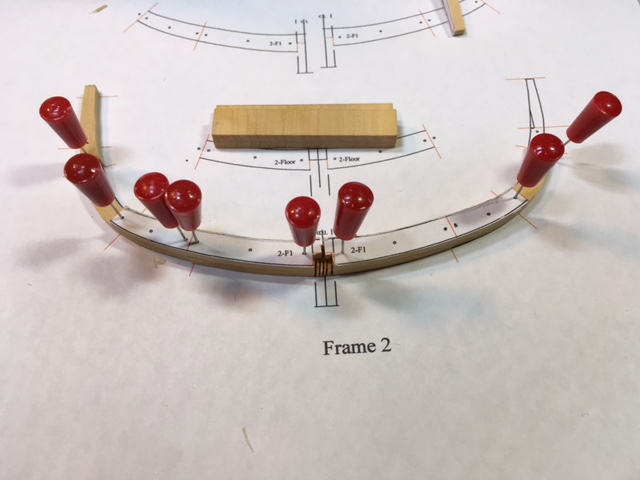
After five or six frames assembled the old fashioned way on double stick tape, I thought I'd see if I could retry Ed Tosti's control pin approach. This time I did not use the awl to tap the holes. My old Dumore Jewelers drill can be quite accurate if used properly so frame 2 is being assembled with control pins. Even if I do not use a pin in each hole (ever so slight misalignment) I think it will work out. We'll see after a couple more. One problem has arisen with the frame pieces. Even though they were cut from the same plan as the underlying master page, the floors are more than a line's width too long when placed on the "master". Maybe the act of gluing them with water-based school paste stretched them a tad. A touch on the disk sander fixes it. I'm just surprised and did not anticipate that. Maury
- 525 replies
-
- 9
-
-
- anchor hoy
- hoy
- (and 1 more)
-
Greg, I've heard a rumor that Chuck has a capstan in the planning stages. Similar in construction to the windlass. Can't wait. Maury
-
I've bit the bullet and glued up the wing transom , filler transoms and frame 16 to the sternpost. I have a lot of braces, squares and clamps all maneuvered into place so the stern post is plumb, the frame is plumb and level and the transoms are level. Cleaned off excess glue with a water brush and now just let it set up for a while. Back to assembling frames. Maury

- 525 replies
-
- 9
-
-
- anchor hoy
- hoy
- (and 1 more)
-
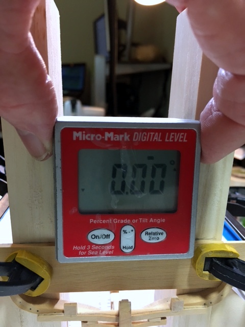
Dr. Per, Yes, it's a great little tool. You can re-set to relative zero, so it does not matter how tilted your work table is. Everything is then level with the building board. Maury
- 525 replies
-
- 4
-
-
- anchor hoy
- hoy
- (and 1 more)
-
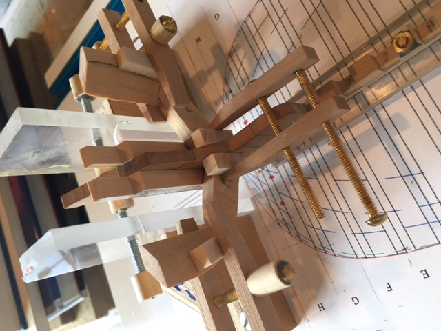
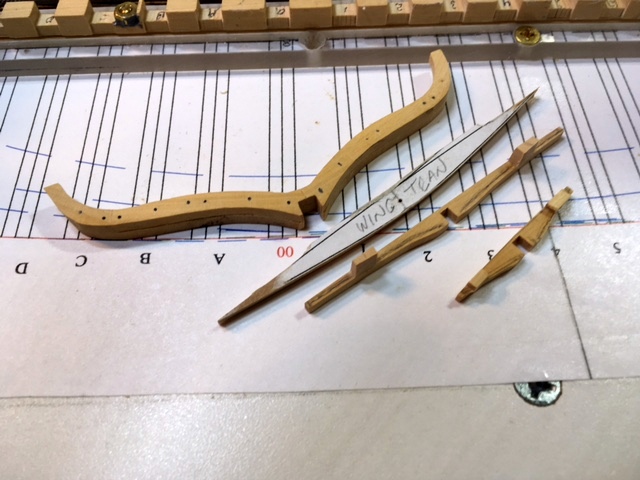
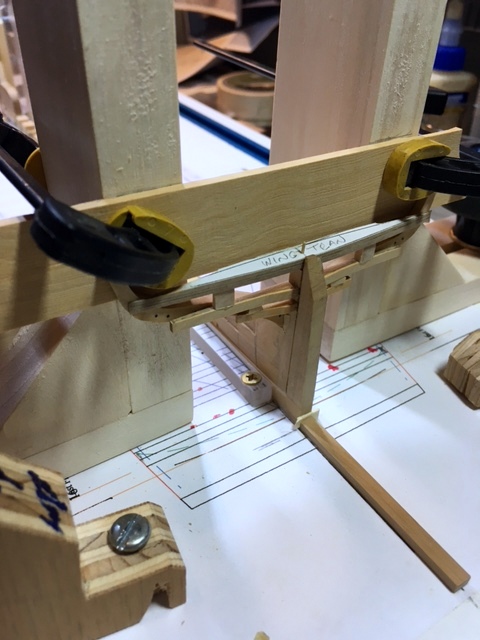
I started the frame assembly using the alignment system EdT described in the YA posts. I had some trouble perfectly aligning the frame parts for drilling the holes, even pre-tapping with a very fine awl. Using the old double-stick tape and aligning the pieces seemed easier. I assembled Frame 16 (aft-most), inserted the connecting bolts (25 pound Black monofilament fishing leader "Amnesia") glued in place with CA. All the parts for the transoms (Wing and FIllers) along with Frame 16 are shown in the next photo. There are blocks on the tops of the two filler transoms insuring they remain level and equally spaced. The Wing Transom is rounded up to match the deck and a pilot hole connecting it to the top of the stern post is drilled. The filler transoms are flat and notched to connect with the front of the inner stern post. Everything is test fitted. The Filler Transoms to the stern post first, then Frame 16, which is aligned plumb and level with the aid of the square building board pieces and my trusty digital level, and finally the wing Transom on top with the bottom of the two sides at equal heights from the floor. Once I check around to see if something else needs doing, I'll glue all the parts to the keel assembly. Maury
- 525 replies
-
- 11
-
-
- anchor hoy
- hoy
- (and 1 more)
-
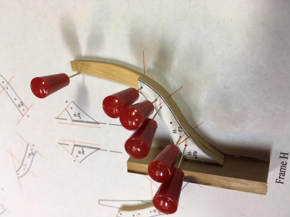
DISASTER discovered! I assembled the most forward frame (H) to see how everything lined up. It was too narrow and did not line up with the Plan View on building board. Measuring and going back over everything, I find that I drew the frames on the profile by copying a line 6" forward and 6" aft of the station lines. I should have used the station line as the wider measure on the aft side of the forward frames and the fore side of the aft frames). Bummer! How to fix this? There is practically no taper to the side of the boat from Frame A back to Frame 9. On the other frames, half of the frame pieces would be OK, but how do I re-loft the others? I'm going to think about it for a bit. Maybe just shifting the positioning of the frames forward (B - H) and aft (10 - 16) by the half-frame thickness (6")? That means changing the "Profile plan" and "Plan View" and a new rising wood, but that's easier than re-lofting and cutting all the frame pieces. Only variation will be the "space" between frames where I make the two transitions (probably at the dead flat). Live and learn. Thoughts? Maury Update. It was only the foremost (H) and two aft most frames to be adjusted. I did it correctly originally and probably played around on those three frames. Minor revisions...not the biggie I feared.
- 525 replies
-
- 3
-
-
- anchor hoy
- hoy
- (and 1 more)