HOLIDAY DONATION DRIVE - SUPPORT MSW - DO YOUR PART TO KEEP THIS GREAT FORUM GOING! (Only 13 donations so far - C'mon guys!)
×
Maury S
-
Posts
1,490 -
Joined
-
Last visited
Content Type
Profiles
Forums
Gallery
Events
Everything posted by Maury S
-
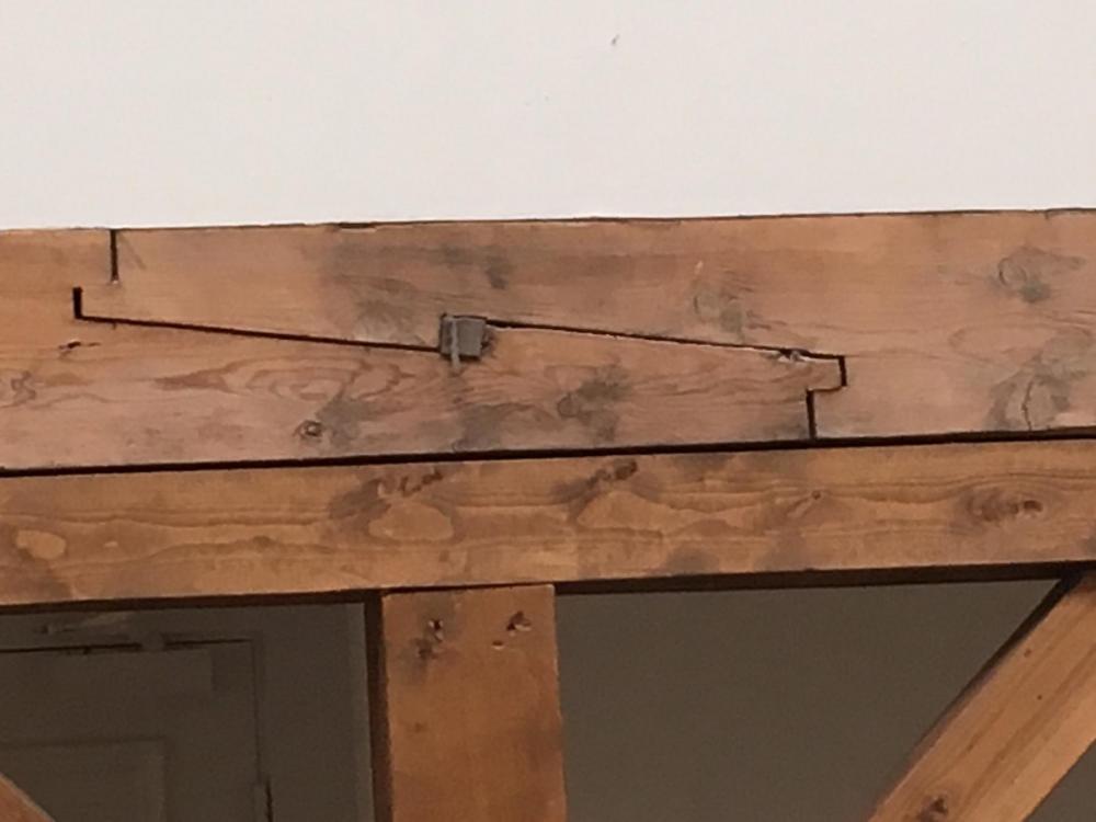
 Between chores, I made the jig to hold the transom frames in place. There is a piece of ply glued vertically to the horizontal jig. It is a bit longer so there is room to clamp it to the square building board frames at the proper height once the wing and filler transoms are in place I don't have any idea how else the transom frames could be firmly held in place to the top of the wing transom while the glue dries. Maury
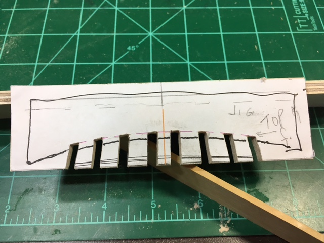
- 525 replies
-
- 7
-

-
- anchor hoy
- hoy
- (and 1 more)
-
Thanks for the likes and comments. Mike, those and the Echo Section from Admiralty (David and Greg) gave me the confidence to strike out with a project like this. Maury
- 525 replies
-
- 4
-
-
- anchor hoy
- hoy
- (and 1 more)
-
Model Machines table saw
Maury S replied to Byrnes Model Machines's topic in Modeling tools and Workshop Equipment
Jim, When did you start offering an extended table? Maury -
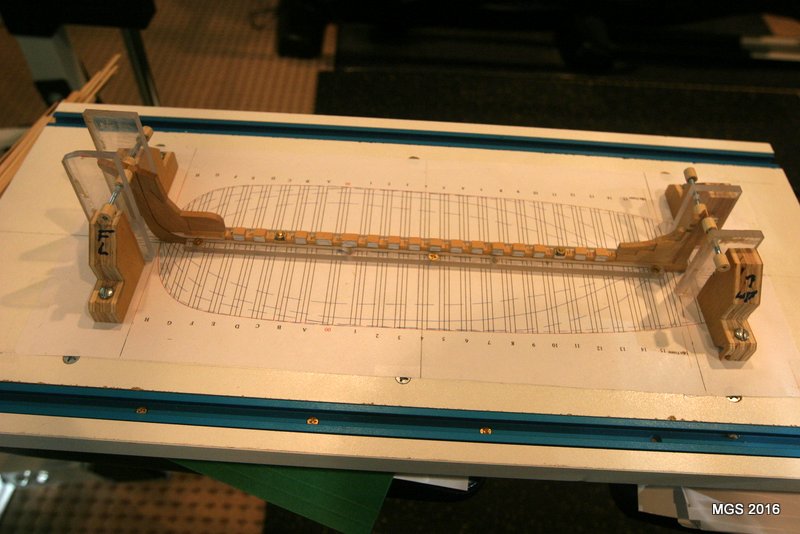
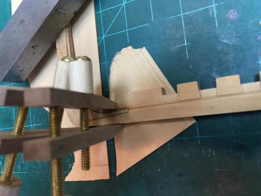
The keel assembly is mounted on the shipways (building board) showing the adjustable plumb alignment brackets in place. Any time I remove the boat from the board, I can be sure to get it lined up perfectly vertical when replaced. Loosen the screws and they swing out of the way if I need to access the stem or stern posts. This thing is in there so solid! Once again, thanks EdT for the idea. Maury
- 525 replies
-
- 8
-
-
- anchor hoy
- hoy
- (and 1 more)
-
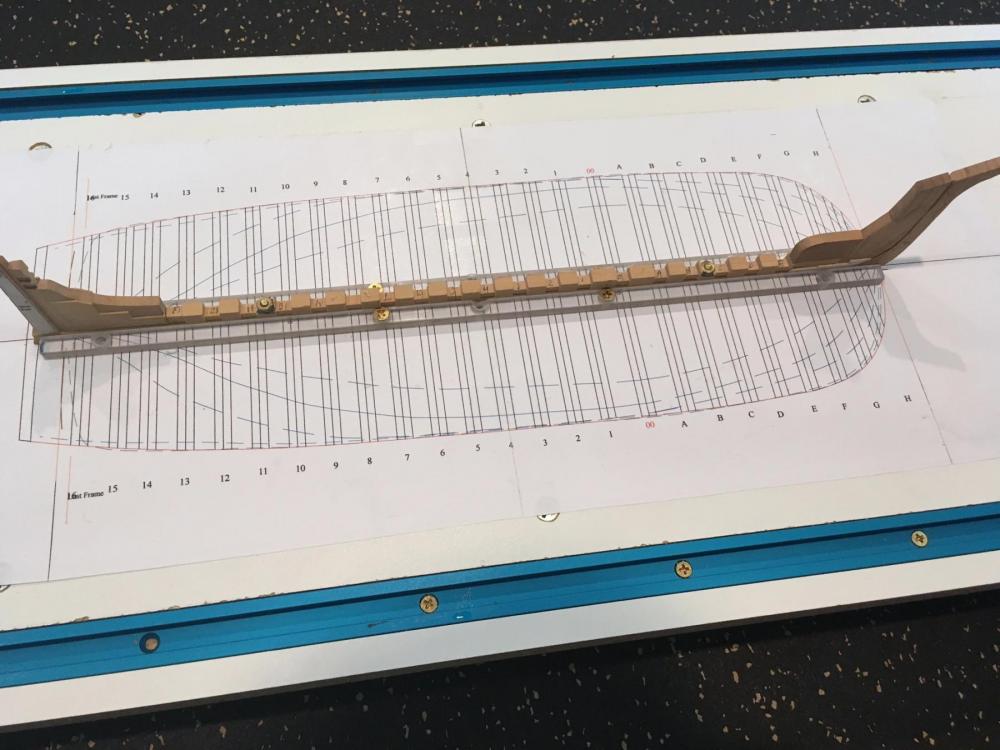
The frames pieces have been cut out and sanded close to the lines. I epoxied the retaining nuts for the 4-40 bolts that pass thru the keel assembly. Next is setting everything up on the building board. Holes were drilled to match the keel. Per Ed Tosti's latest layout, I used a piece of 1/4" x 1/4" Plexiglas screwed along side the keel to keep it straight. See picture. I have some plan work to do on the filler transoms before I set the wing transom on top of the stern post. The slots in the rising wood line up with the plan sheet...camera distortion. Maury
- 525 replies
-
- 11
-
-
- anchor hoy
- hoy
- (and 1 more)
-
Back from vacation and back to the project. I was hoping to see the models of anchor hoys that the Oslo Maritime museum had, but they were not on display and no one seemed to know much about them. They were referenced in Robert Cairo's series in NR Journal back in the early 1970s. I laid out the parts for for frames C thru H and glued them on one sheet of 1/8" x 2"x 24" boxwood using dilute white paste. There are 24 frames in total so if things work out, I'll have all of them on 3 boards. I could have pushed the pieces closer, but I like to have a bit extra width at the ends of each piece so I can see the proper mating angle and having the end lines longer makes it easier to line up on the disk sander. Maury

- 525 replies
-
- 6
-
-
- anchor hoy
- hoy
- (and 1 more)
-
In a restored fishery in Norway, I stumbled upon many beams with a tenoned scarf joint. The wedging block in the center is quite visible. The tenons would probably not visible or practical in 1:48 scale but I think TFFM or one of Ed Tosti's books show wedges. Maury
- 1 reply
-
- 12
-
-
Interesting CA glue applicator. I've always used a pin lightly dipped in some CA trying to be careful not to over do. Seems yours carries much more liquid. Would you explain the benefits of your device? Maury
- 3,618 replies
-
- 3
-
-
- young america
- clipper
- (and 1 more)
-
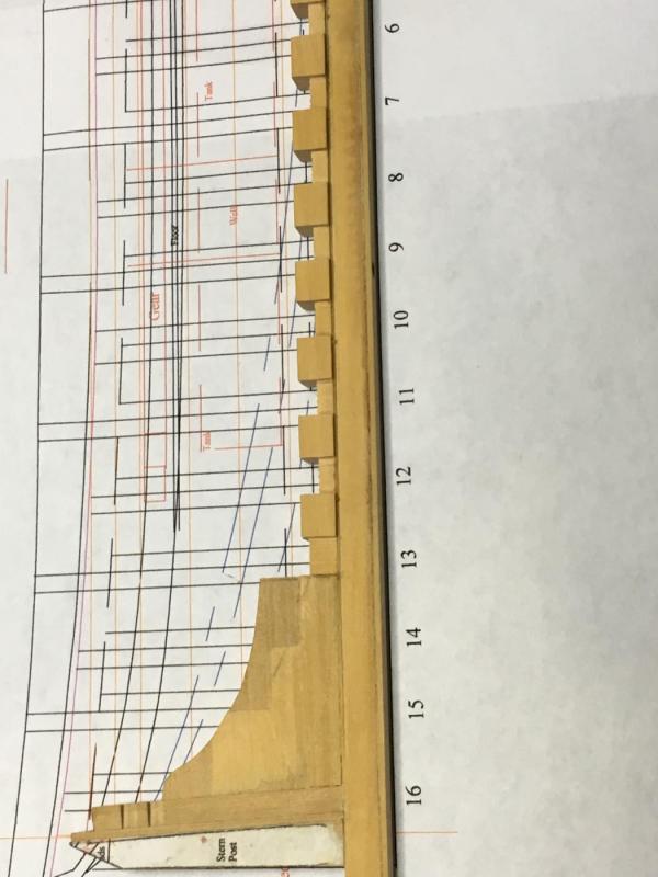
The rising wood has been re-built and replaced the original. Regardless of how the photos look, all the slots in the RW line up perfectly with the frame plan. A jig was made (a dummy frame floor) to assure a snug fit (square to the keel) of the frames into the slots and that they will bed well. Next is adding the remaining stem fillers between frame "E" and "G". Maury
- 525 replies
-
- 11
-
-
- anchor hoy
- hoy
- (and 1 more)
-
I caught a problem! The notches in the rising wood are off slightly (1/32" - 1/16") from the frames when the keel assembly is laid over the profile plan sheet. There is no acceptable way to adjust for this. The rising wood will be removed and replaced with another piece(s). Isopropyl! Maury
- 525 replies
-
- 5
-
-
- anchor hoy
- hoy
- (and 1 more)
-
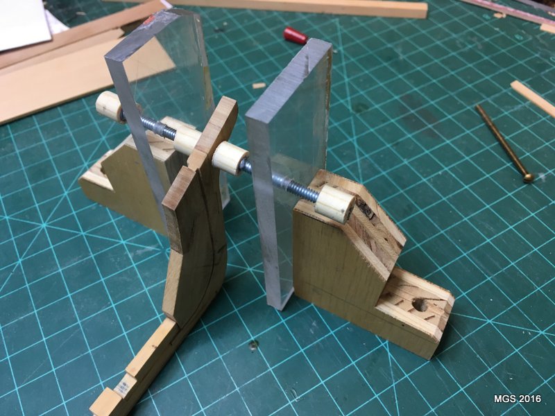
Working on the stem and the rabbet. To quote David..."fiddy work". I keep referring to TFFM and Young America books. Ed Tosti is a great source of ideas for tools, jigs, etc. See braces for the bow below. The wood dowels are tapped and are epoxied to the threaded rod (6-60). The hole through the 1/4" Plexiglas is tapped. The units will be screwed to the building board near the front and are fully adjustable to keep the stem plumb throughout the build. The assembly twisted a bit (1/16+") so heat (hair dryer) was applied while it was clamped flat and everything is now back to flat (or plumb when vertical). Maury
- 525 replies
-
- 7
-
-
- anchor hoy
- hoy
- (and 1 more)
-
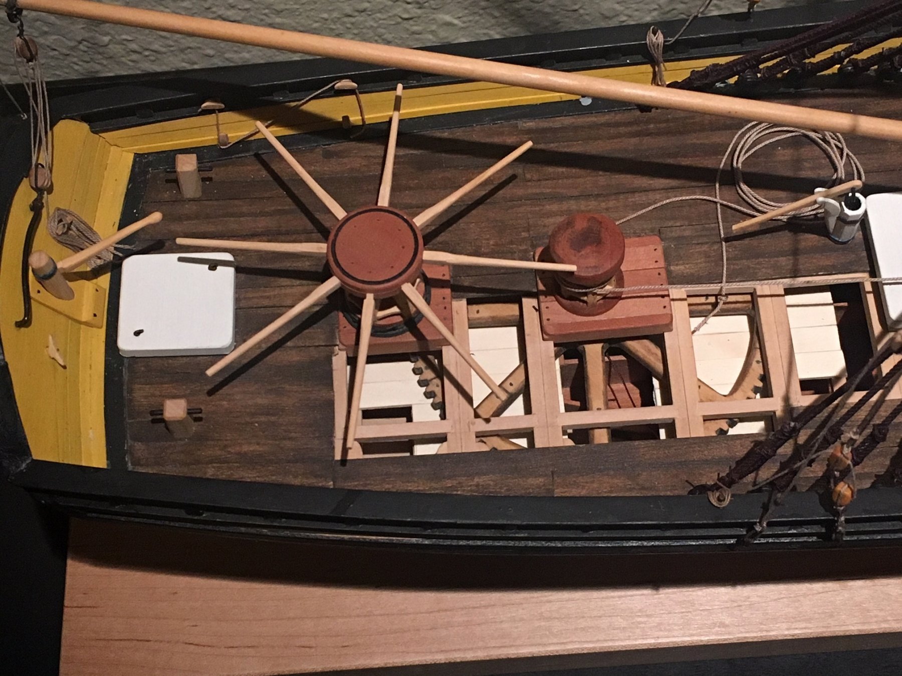
Chuck, Beautiful detail on the winch! The micro-tube is a neat idea. What function do the gears play? I don't see them meshed with any others that would provide leverage? Maury
- 1,051 replies
-
- 2
-
-
- cheerful
- Syren Ship Model Company
- (and 1 more)
-
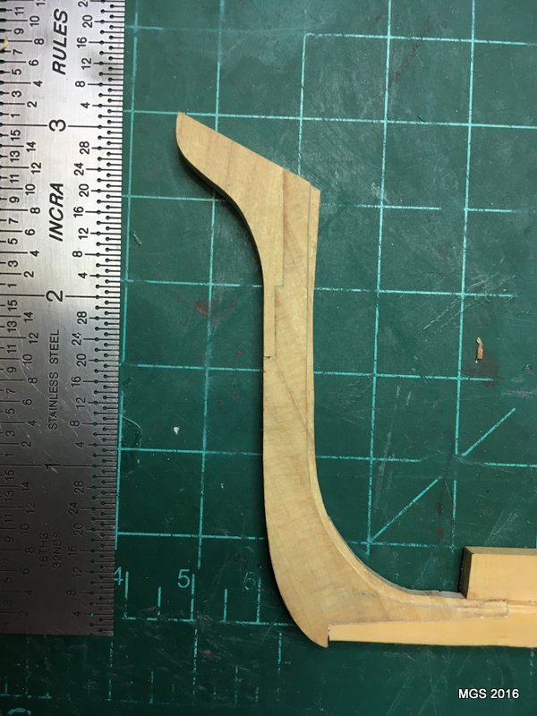
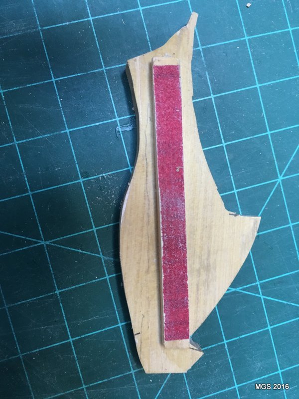
The stem has been assembled and is being clamped into the keel / rising wood. The scarf joint at the upper end of the stem is barely visible even though it is glued with darkened glue. I have to clean up the rabbet at the joint. The little extension at the bottom of the stem will disappear when the false keel is added. By the way, following EdT's glue "formula" I was not able to find artist powders so I bought the best acrylic color (paste-like) I could find, mixed with the Tite BondII and it was a disaster. The mixture came out with tiny specks (think poppy seeds in a muffin) no matter how I mixed it. Next step was to use red and green (makes brown) food coloring, mixing well and it came out great. Chocolate milk colored while wet and dries darker. The notches in the rising wood needed evening-out so I assembled a sanding jig to keep everything consistent. A piece of 150 grit sandpaper on a 1/8" x 1/4" stock, glued to a scrap support piece to keep it parallel to the top of the rising wood. The notches on the sides of the rising wood need some attention. Maury


- 525 replies
-
- 9
-
-
- anchor hoy
- hoy
- (and 1 more)
-
I guess you could have the port side with oars extended and the stbd side upright as if it pulled up to a dock. Isn't that how they would have arrived at a dock? Maury
- 641 replies
-
- 6
-
-
- greenwich hospital
- barge
- (and 1 more)
-
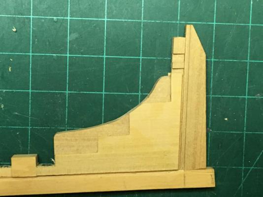
The stern posts and deadwood are attached to the keel as is the rising wood. Rather than carve out shoulders on the deadwood for the half frames 13 - 16, I chose to build up with 1 1/2" (1/32") material. The pattern was mirror-imaged in TurboCad (so both sides matched exactly), pasted to the 1/32" sheet and rough cut on the scroll saw. The bottom and angled aft edge were sanded on the circular sander, held together in a vise and sanded / filed to the step pattern so they were identical. They were then glued to the sides of the deadwood lining up with the top of keel and stern rabbet. They will be pared down from the bearding line to the rabbets. I don't see any draw-back to this technique as the deadwood thickness was sanded to accommodate the built-up steps before installation. Total thickness with the shoulders matches the outside of the rising wood. By the way, ever since I cut the slots in the rising wood, there has been a tendency for that piece to bend, so I've always clamped it and subsequently the whole keel structure to a flat surface and against a straight edge once I'm done working on it. Once it's on the building board, that will no longer be an issue. Now to the stem. Maury
- 525 replies
-
- 12
-
-
- anchor hoy
- hoy
- (and 1 more)
-
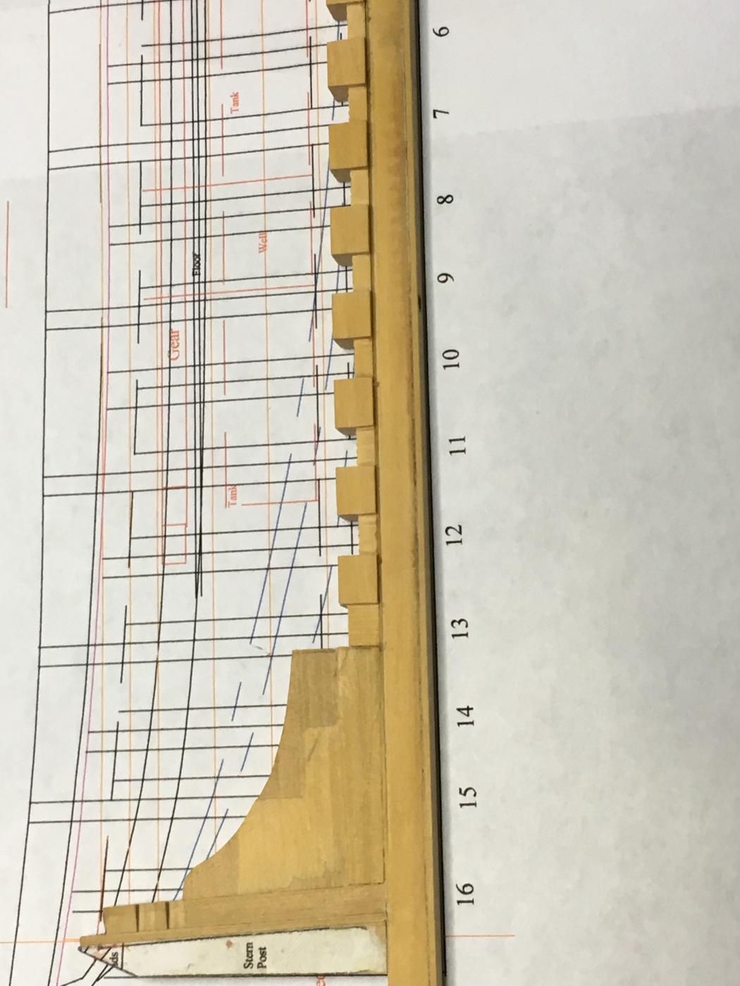
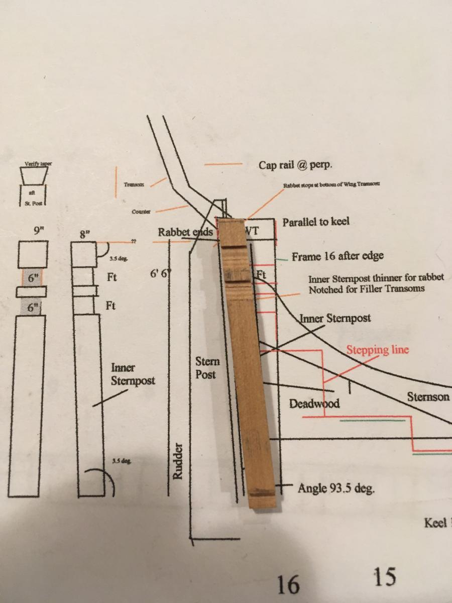
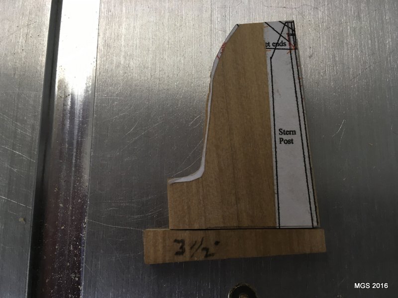
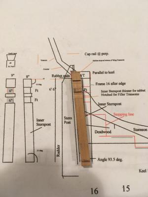
Sternpost and inner sternpost are next. Both are cut on the table saw and end-sanded using the 3.5 degree wedge to insure everything from the posts to the deadwood mate perfectly. The inner post has a tenon that extends into a mortise in the keel. The slots (for the filler transoms) in the inner post were made using the wedge so they align parallel with the keel. The picture is of a discarded post since it was too short. Second attempt was faster and cleaner. Maury

- 525 replies
-
- 9
-
-
- anchor hoy
- hoy
- (and 1 more)
-
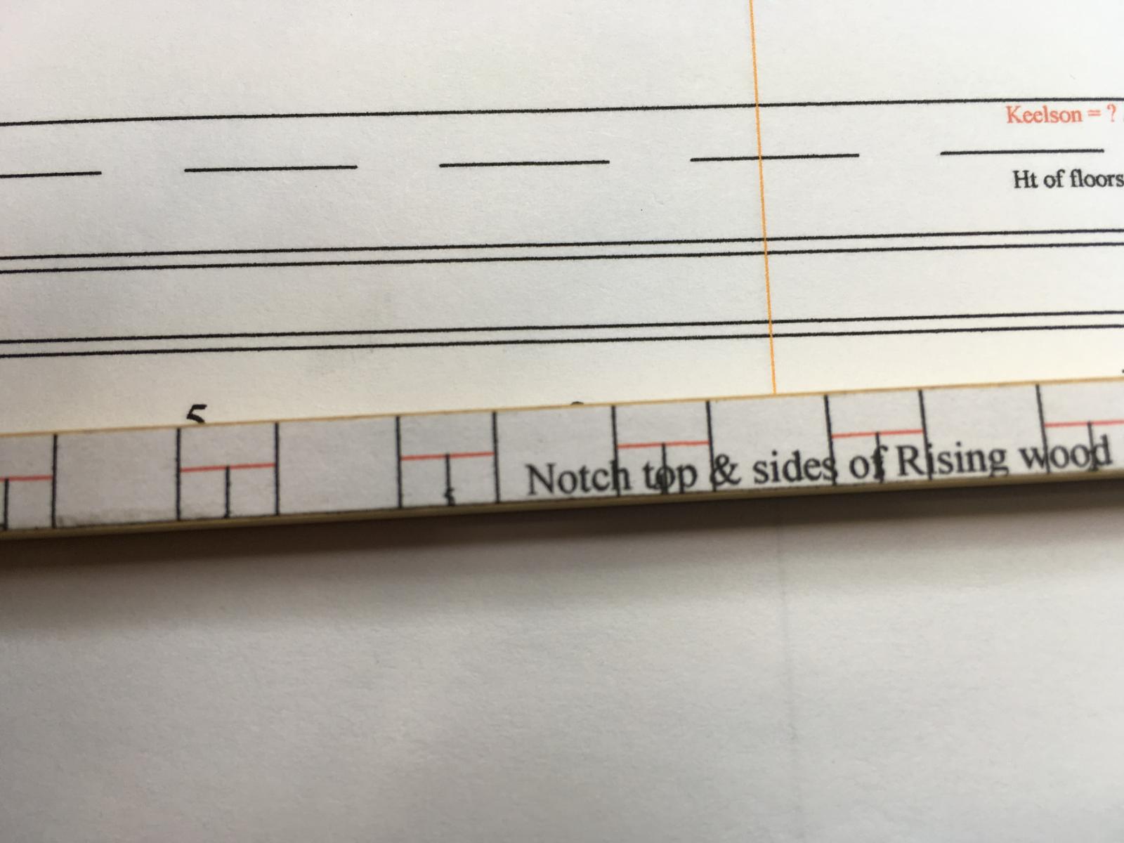
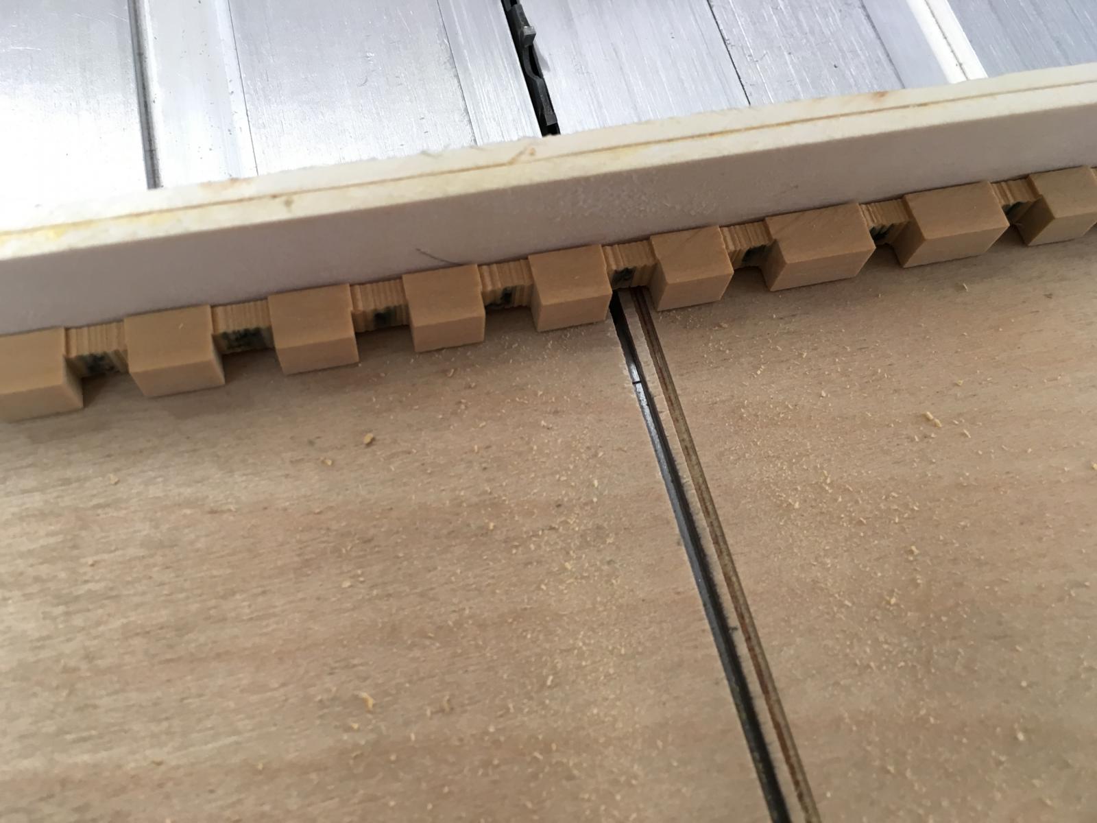
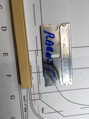
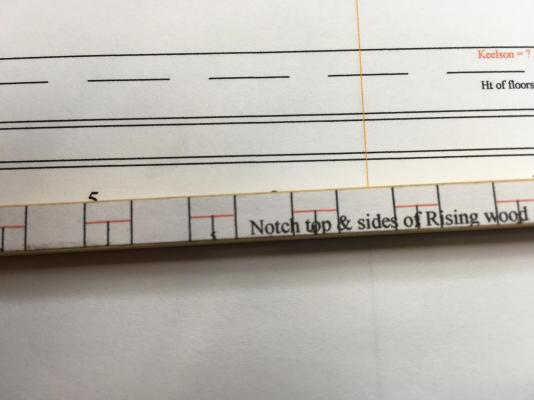
Over the last couple of days I've started making some sawdust. For the rabbet on the keel, I started by making a .020 score with a slitting blade on my Byrnes Saw, then making a scraper from a safety razor blade (thanks Toni!) to finish it off. I may deepen it just a bit. The rising wood layout is glued to the 12 x 12 piece and again, using the Brynes saw and a sled, the notches cut (6" on top and 1.5" on the two sides). The keel is 9" wide so the 1.5" side notches line up with the top of the keel. Next the stem and stern posts. Maury

- 525 replies
-
- 11
-
-
- anchor hoy
- hoy
- (and 1 more)
-
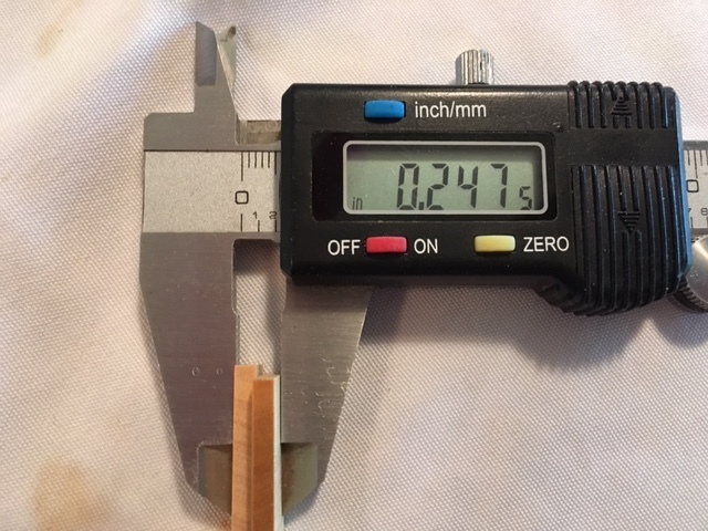
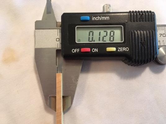
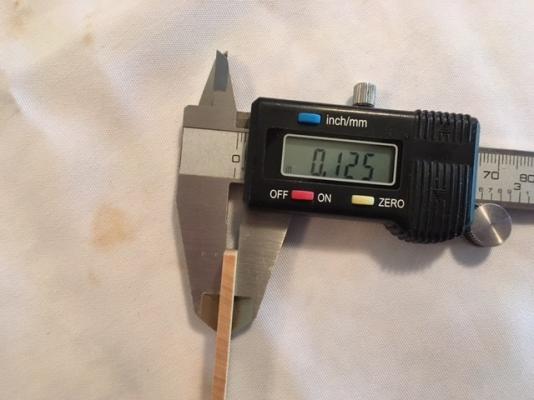
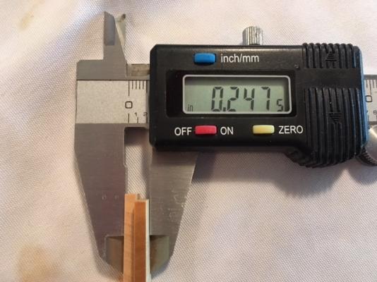
Problem! While measuring twice, I was making sure how much width difference a glue line would make by measuring some 1/8" scrap and gluing them together. Before putting on the glue, here's what I came up with: 1 & 1 makes 1.95. My trusty caliper is no longer trust worthy! I reset to zero each time and repeated the test three times. Cheap tool? Perhaps. Maury
- 525 replies
-
- 3
-
-
- anchor hoy
- hoy
- (and 1 more)
-
Just an update on the sources for scantlings...There are no documents that I can find that specify most of the measurements like we get from Steele or the Shipbuilders Repository (S.R.) that apply to harbor craft. I've used other contemporary boats where bits and pieces can be put together, and looking at Scantlings of R.N Ships (Yedlinsky) ( which is a combination of Steele and S.R.), I've come to what I think are reasonable conclusions for smaller boats. It's not light in construction as a fishing boat might be, but heavy enough because of the nature of the job of handling huge anchors and moving around and about much larger ships. Maury
- 525 replies
-
- 3
-
-
- anchor hoy
- hoy
- (and 1 more)
-
There is an article in the latest issue of Popular Woodworking Magazine (June, 2016 #225) on wood (sanding) sealers. While it probably does not broadly apply to us modelers, there are comments on the advisability of thinning, water based, poly, etc. Some comments excerpted...Water-based sanding sealer-- no need for it. Sealers for lacquer and alkyd varnish weaken the finish. No sealer needed for polyurethane varnish. No reason to thin the first coat (this does not apply to thinning paints to get better color at scale!). They do admit that thinning provides better bonding, but lack of bonding probably applies to boats in wet environments and that problem arises from moisture getting under the finish. I have no opinion on any of these conclusions...above my pay grade. Maury
-
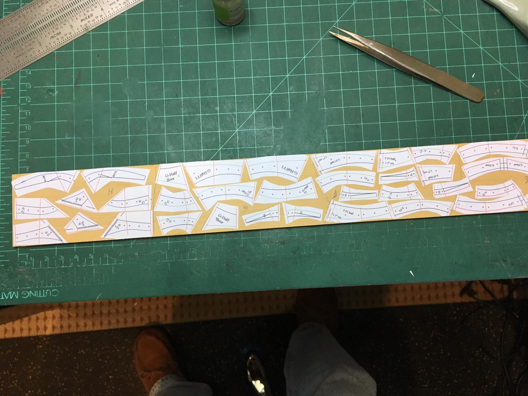
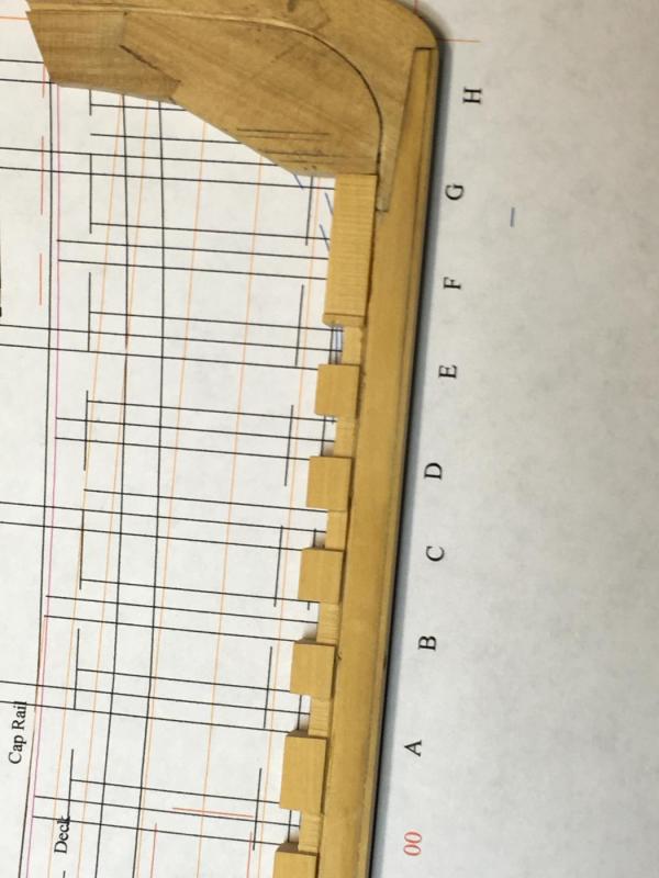
I took the TurboCad file to the printer to get a piece large enough to past on the building board. Many attempts and re-tries and even specifying printing the file as 1/4" = 1', the scale was off by about 5%. They apparently still convert to pdf before sending to the printer. I'm better off printing directly from my app to 8 1/2 x 11 and doing a careful cut and paste for the few images longer than 10 - 11". Measure two - three times before cutting applies to reading scale plans. Maury
- 525 replies
-
- 5
-
-
- anchor hoy
- hoy
- (and 1 more)