


Gahm
-
Posts
1,217 -
Joined
-
Last visited
Content Type
Profiles
Forums
Gallery
Events
Posts posted by Gahm
-
-
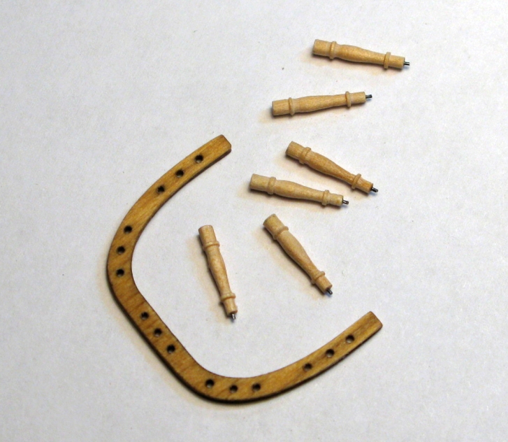
B.E. and Bob, thank you for your kind comments! Turning all those belaying pins gives me some good practice on the lathe

Thomas
-
Beautifully done, Bob! But by now I am not expecting anything less from you . . .

Thomas
-
Thank you so much for your comments and all the "likes"!
Dirk, thank you for your compliment. As always it is highly appreciated!
Augie, yes the rail will be pinned to the deck. I have already drilled the holes for the pins in the fife rail columns. But I will wait with this until I have the pump finished and can give the fife rail its final position without running into any surprises
Brian, there is less to the lathe work than it appears. My "transfer system" consists of a piece of paper with the precise column profile on it so that I can compare the length dimensions of the part in the lathe with the target dimensions at any time, and I frequently measure the thickness of the part in several key locations. The rest is eye balling.
Floyd, tough choices!!

Thomas
-
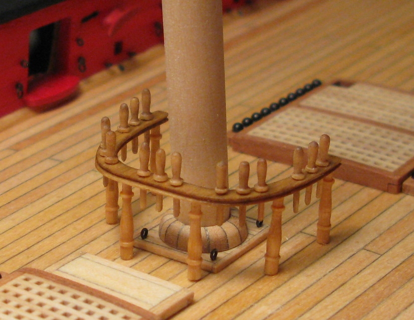
After having finished about one third of my belaying pins I needed a little break and built the fife rail. The building process and the result is shown in images 1 – 5.
Thomas
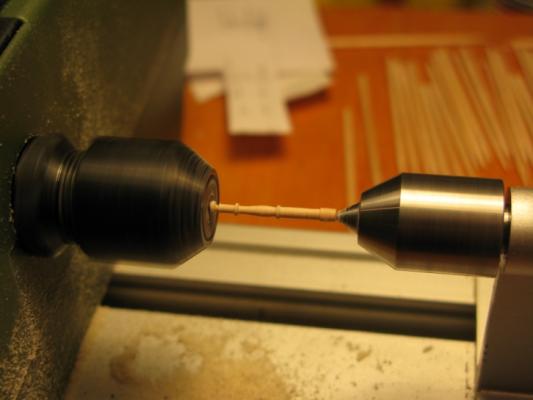
Image 1
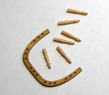
Image 2
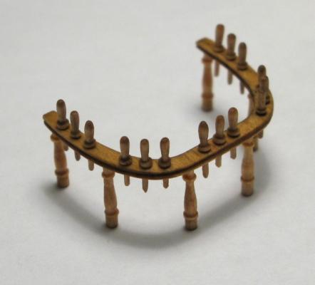
Image 3
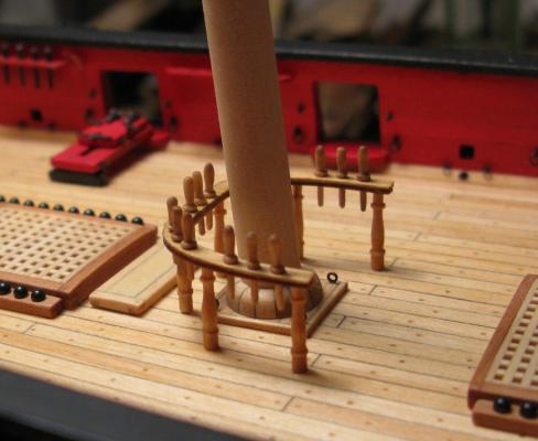
Image 4

Image 5
- jwvolz, Landlubber Mike, rafine and 18 others
-
 21
21
-
This last shot really shows what an impressive model your Essex is!
Thomas
-
Thank you, Håkan! You are right, a Dremel probably will do the trick. Btw, I also started out with pear wood, but unfortunately its color turned out to be too dark for my model as it consists mostly of bass wood stained with Golden Oak. I made the same experience when I built the five rail - my pear wood version, although very nice looking, had too much contrast in comparison to the rest of the model. So I probably go back to bass wood. Boxwood on the other hand turned out to be too light . . . whereas the tooth pick wood (whatever it is
) stained just about right, was stable enough and was easily available. Great idea, Augie! With my productivity the venture would never get off the ground
! Thomas
-
Thank you for your comments and all the "likes". They are highly welcome and appreciated!
- Floyd, your point is well taken! I checked again, but as I have followed Chuck's plans very carefully (inclusive the major dimensions of the belaying pins which look a bit different in the plans than what is provided in the kit) I think I am fine. The pins are as thin or even a little thinner than the kit-provided brass pins.
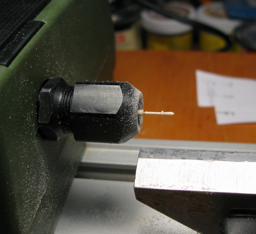
- Richard, I find the Proxxon lathe an affordable and very useful little tool! To get the presented results I tried all kinds of different approaches. I finally settled on using tooth picks (--> unlimited supply at nearly no cost, good stability, they already come as pretty thin dowels which makes the final processing easier, the birch? wood stains easily with Golden Oak). As the wood is a bit grainy regular cutters don't work very well - they split up the wood. However, needle files for the "rough" work and sanding sticks for the final smoothing of the surface work very nicely and lead to the shown results.
- Augie and Bob, thank you so much for your kind comments! As you know I am in awe of the combination of productivity and quality which is displayed in your builds! In my case I always tend to find the most time consuming approach to everything
 . But then, as Russ is always stating in his comments: "It ain't a hobby if you are in a hurry"
 - Dirk, I guess I have to send you my order list as well, starting with all the fantastic rope work you are doing, and the wonderful details you are adding to your model . . .
Thomas
-
Absolutely beautiful! Congratulations!
Thomas
-
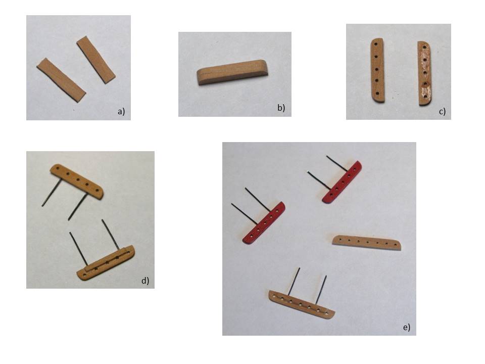
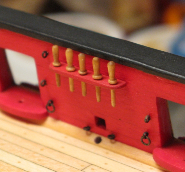
I have started to build the pin rails. In the Syren instructions Chuck mentions that the pin rails should be around 1/32’’ thick, but for stability reasons they are built out of a 1/16’’ thick bass wood strip. As shown in image 1 I used a compromise: I made the pin rails out of pear wood for stability and thinned them down at the (visible) side and front edges to 1/32’’ thickness, however I left the (invisible) rear edges with thickness 1/16’’ so that it was easier to drill holes to pin and glue the rails to the inboard side. As the image also shows I always built the pin rails in pairs by temporarily gluing 2 pieces of pear wood together, drilling the holes for the belaying pins and giving the part its final shape before separating the 2 pieces again. 2 mounted pin rails are shown in image 2.
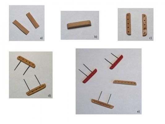
Image 1
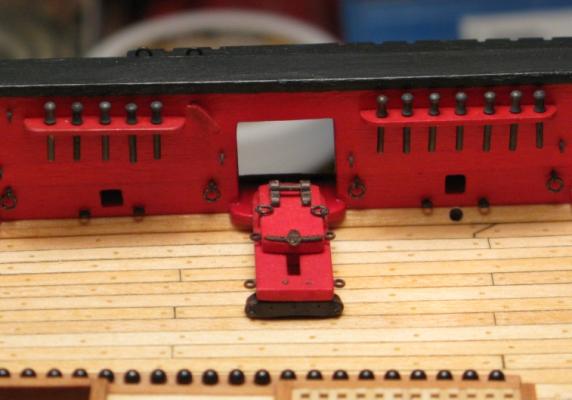
Image 2
I initially used the brass belaying pins included in the kit and blackened them (image 2). However, to my taste their heads are a bit short, so I looked for alternatives – ideally made out of wood. As I did not find any wooden, reasonably shaped, commercially available belaying pins I started to make them myself using my little Proxxon lathe (image 3) and tooth picks. The result is shown in images 4, 5 and 6. On the right side in image 4 you can also see how these wooden belaying pins compare to the brass versions from the kit. Well, I have done 12 so far, so there is still a little way to go to replace them all
.Thomas

Image 3
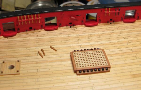
Image 4
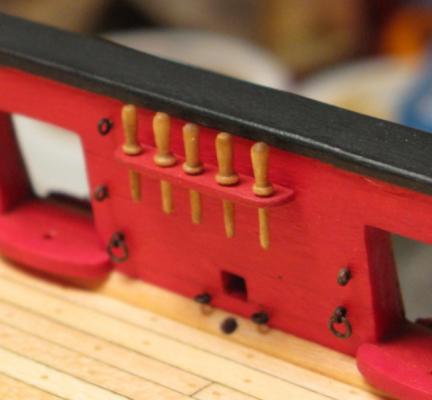
Image 5

Image 6
- augie, VasaRodin, Wintergreen and 12 others
-
15
-
-
Beautiful work! And I can't believe how fast your Essex is coming together!
Thomas
-
-
Nice, clean work! You are off to a very good start!
Thomas
-
That is a very nice idea, Dirk! I have to keep this in mind when I do the final mounting of the masts.
Thomas
-
Thank you, Richard! With the mast foot I have the same problem . . . I like the looks of it,although I know it probably is not the best representation for this kind of model.
Thomas
-
-
Thank you so much for your nice comments and all the "likes".
- Dirk, that is the advantage of running (like me) behind the pack . . . you can pick and choose from all the wonderful ideas other Syren builders already had
. In that regard I also highly appreciate your newest discussion on the steering mechanism!- Augie, I am not quite sure on my current mast coat realization. I like the looks of it, but it is probably more suited for an admiralty style model where you show the inner workings and construction of a ship. For my Syren I probably will end up using a solution which shows the tared linen cover.
- Håkan, thank you for stopping by. I highly appreciate your compliments about my build log!
Thomas
- Dubz, Stuntflyer, egkb and 1 other
-
4
-
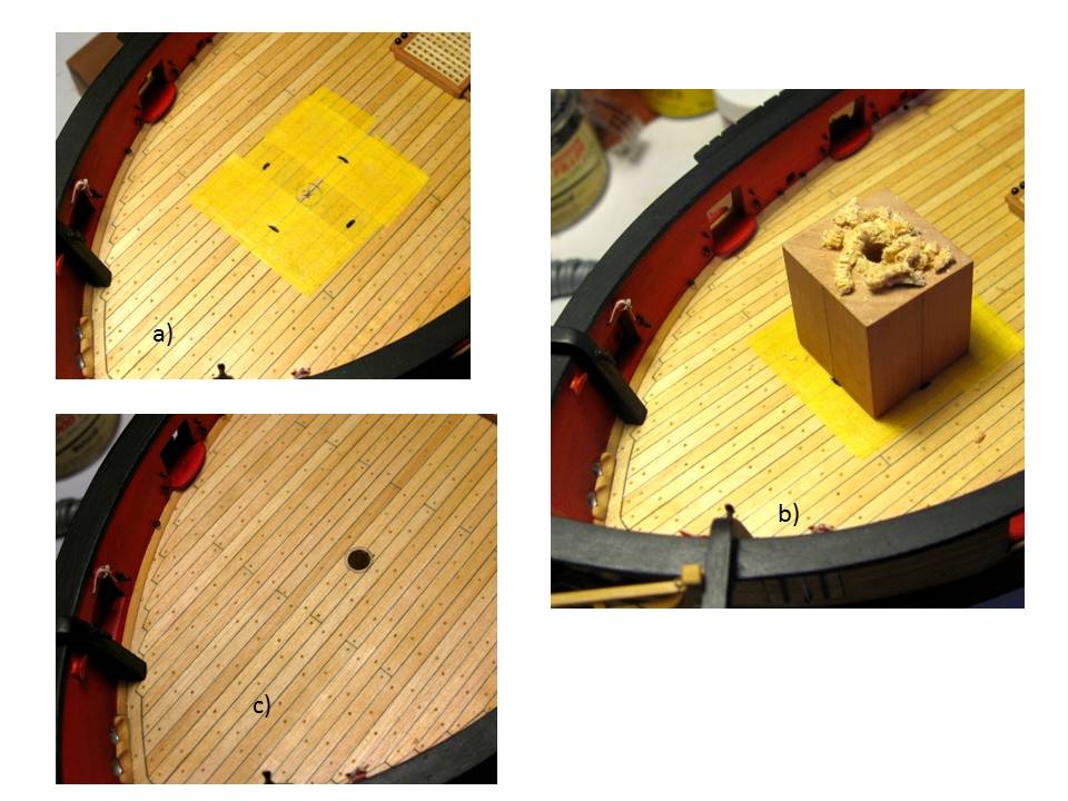
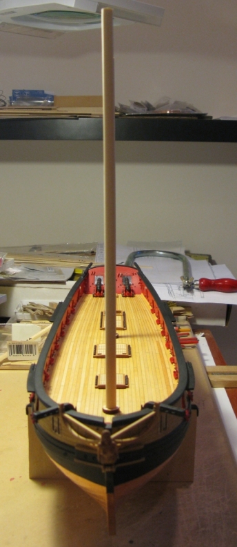
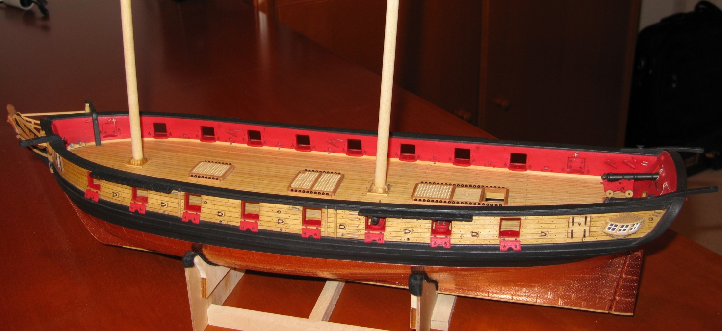
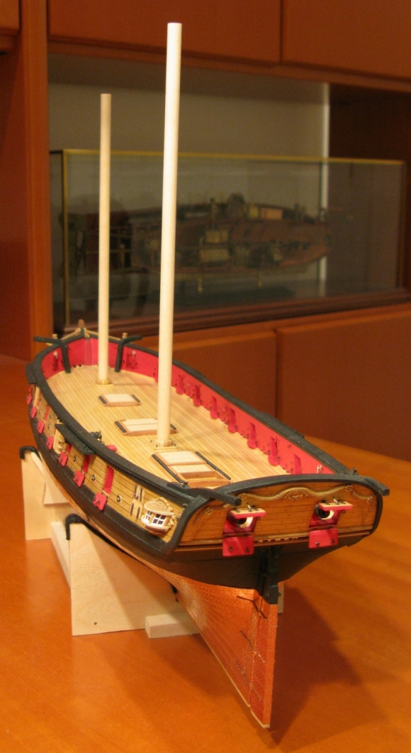
Before the deck gets too crowded I drilled the mast holes. To make holes with the right size, depth and rake I built a jig by drilling a hole of the correct size vertically through a block of pear wood and giving the lower end of this block an angle (main mast 86°, foremast 89-90°)consistent with the intended rake using my disk sander (see images 1a and 1b). To “transfer” the holes I marked their positions on the Syren’s deck (image 2a), placed the jig on those marks (image 2b) and used a battery driven screw driver/drill guided by the jig to drill the holes (image 2c). As a result I ended up with 2 clean holes which position the masts with exactly the intended rake and also have the masts nicely line up with each other (images 5, 6, 7). To give the whole assembly a more final look I was also tempted to make the mast foot for each of the masts. As a first version a built a foot which shows the wedges. Image 3 describes the process of making the mast foot. In image 4 you can see the result. I still will try some other mast foot versions (for example a version simulating a cover with tarred linen) until I know for sure which way I finally will go
.Thomas
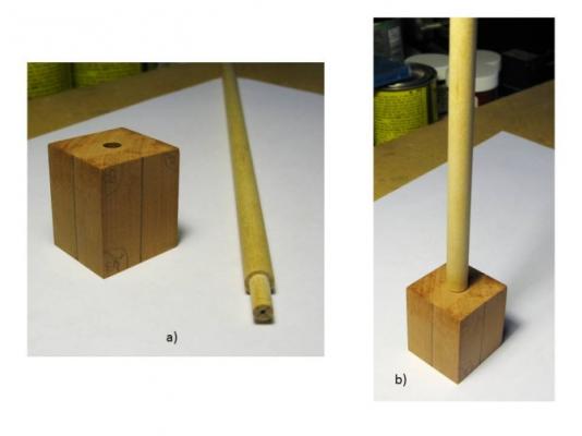
Image 1

Image 2
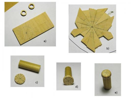
Image 3
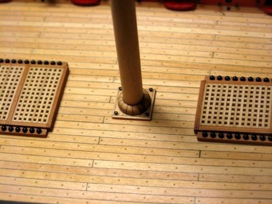
Image 4
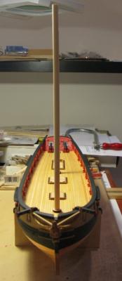
Image 5

Image 6
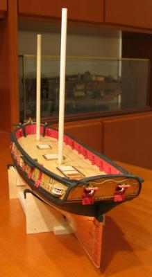
Image 7
-
Fantastic work, Bob! Always so clean and well done . . . just a pleasure to watch!
Thomas
-
Thank you for all the "likes". And Dirk, you are absolutely right, I would not mind at all sneeking into your cellar and "transferring" the one or other detail from your Syren model
. You just have one of the nicest Syren builds I have seen so far! Thomas
-
A little update: I was not really satisfied with the capstan platform. When I built it I kind of had forgotten that basswood is not equal basswood. When I did the deck planking I had selected the basswood strips very carefully for uniformity in grain and color and as you can see in image one the wood grain of the first capstan platform did not really match that. The grain was fuzzy and the tree nails turned out looking pretty undefined. I also took the opportunity and lowered the capstan platform a little bit. I had seen that in several Syren models (Dirk, Rendich Lightley, . . .) and I liked the looks of it better than having everything in one plane
.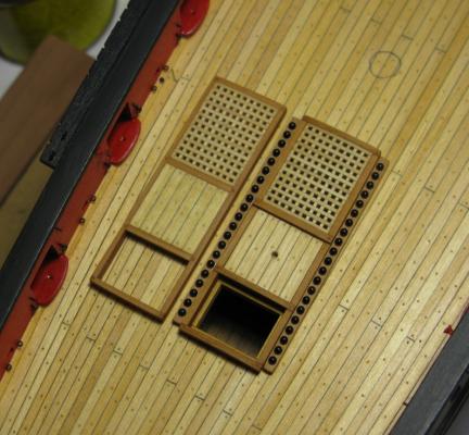
Image 1
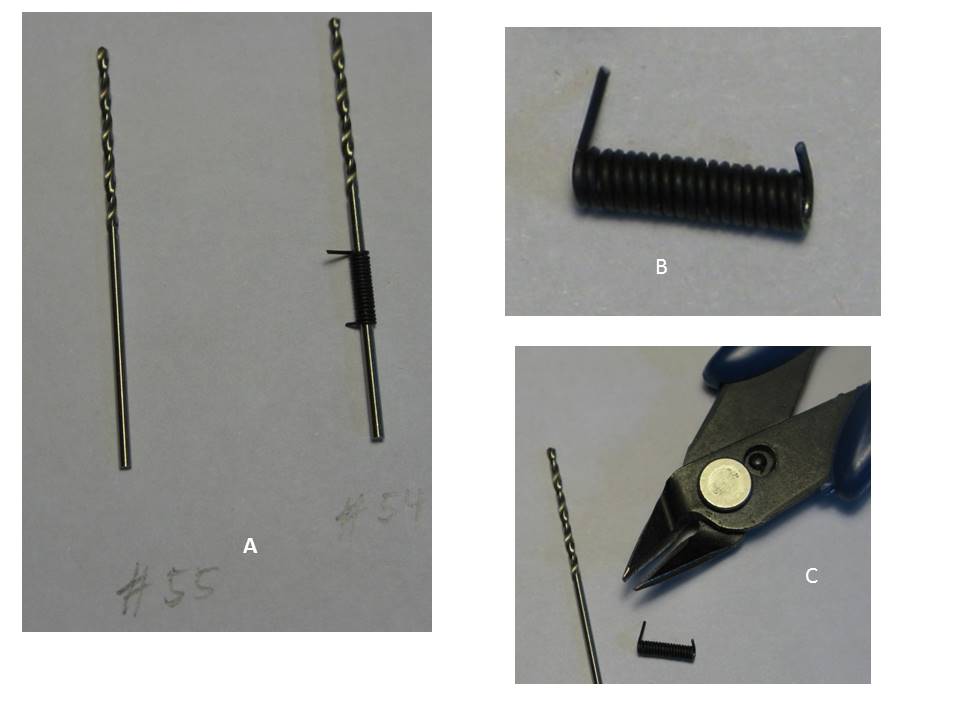
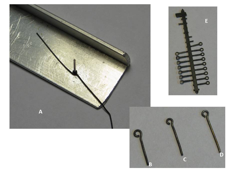
Otherwise I spent some time producing and mounting ring bolts and the last missing cleats. Images 2 – 4 show my method of making the ring- and eye-bolts: after selecting a drill bit with the right diameter for the rings (for the breech rings of the carronades and guns I use a #55 drill bit à ~2mm outer diameter) I take the next larger drill bit (#54) and tightly wrap the black anodized 28 gauge steal wire around it (image 2A), take it of the drill (image 2B) and separate the rings from each other with a sharp-nosed pair of pliers (image 2C). The resulting rings (image 3A) still need a little treatment: their ends need to be flattened with a file so that they will fit together when the rings get closed, and the rings themselves need to be flattened with another pair of flat pliers. Cleaning up the wire ends of the rings makes their circumference a bit smaller. Therefore for the final closing I use the (slightly smaller) drill bit with the target diameter (#55) mounted on a brass plate and close the rings around the drill bit with some tweezers in the plane defined by the brass plate (image 3B). The result are nicely shaped rings where the joint is barely visible (image 3C). Based on personal preferences and other considerations they still may get silver soldered – or not.
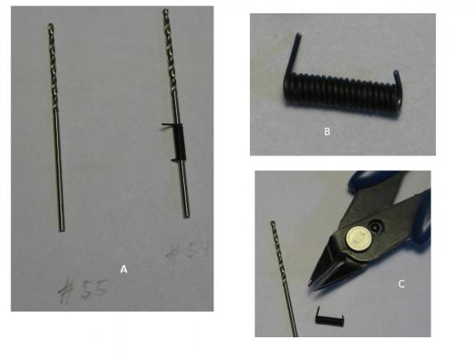
Image 2
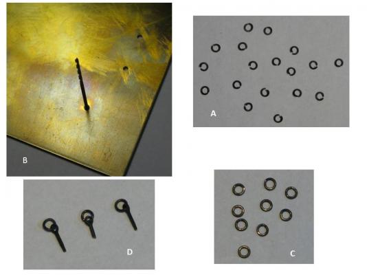
Image 3
To use these rings in ring bolts (image 3D) they need to be combined with eye bolts. Eye bolts can be made using a similar jig (image 4A) where the diameter is determined by the selection of the jig (image 4B,C). The eye bolts included in the Syren kit (image 4D) look fine, and there are also photo etched eye bolts commercially available (image 4E, Dafi). The latter have the advantage that they are closed and nicely round-shaped. I use them when eye bolts are mounted alone and are well visible (gun mounts). However, to insert a ring into a closed eye bolt the ring needs to be opened up again and its shape may get impacted. As with ring bolts normally the ring is the major visible part I rather open up the eye bolt and insert a finished ring. Of course, there is also the laziness factor which sometimes overrides all these noble considerations
.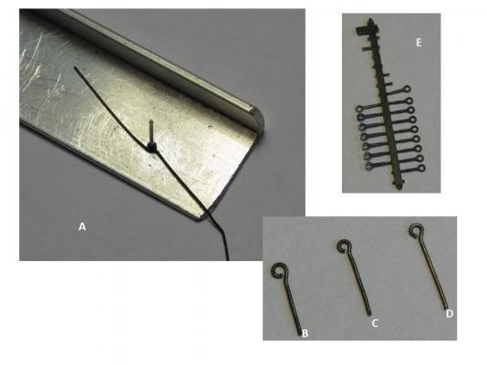
Image 4
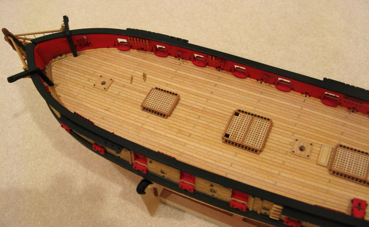
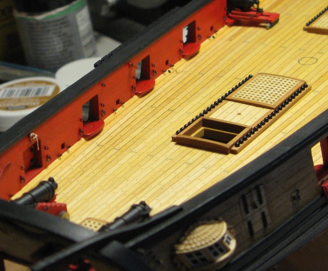
Image 5 shows a few of these eye- and ring-bolts mounted on my Syren model. They are not yet glued in as I may need to remove them again for the final gun rigging.

Image 5
- augie, fnkershner, Jason and 9 others
-
12
-
Enjoy the Syren! It is a lot of fun building this model.
Thomas
-
-
Fantastic work on the bowsprit, Bob!
Thomas


US Brig Syren by Gahm - Model Shipways
in - Kit build logs for subjects built from 1801 - 1850
Posted
Thank you, JesseLee, for stopping by and for your enthusiastic support. These were a lot of "likes"!
Thomas