HOLIDAY DONATION DRIVE - SUPPORT MSW - DO YOUR PART TO KEEP THIS GREAT FORUM GOING! (78 donations so far out of 49,000 members - C'mon guys!)
×


AON
-
Posts
2,863 -
Joined
-
Last visited
Content Type
Profiles
Forums
Gallery
Events
Everything posted by AON
-
 I PM'd you the thickness Guide dwgs. BTW - last night at the NRMSS meeting Kurt announced the NRG will possibly have a simplified version of the thickness guide for sale off the website store in April so you might want to wait a month and just buy one! It is of the style he uses.
 -
Mark Having trouble finding my darn PDFs of the drawings. worse case I'll recreate the PDFs. bear with me
-
What about using these replacement erasers on the end of a dowel? Integra Pencil Cap Eraser for Standard Pencils, 144 per Box, Pink (ITA36523) https://www.amazon.ca/Integra-Pencil-Standard-Pencils-ITA36523/dp/B00181LCHU/ref=sr_1_6?crid=47MKFGNSI70S&keywords=eraser+tips+for+pencil&qid=1647134226&sprefix=eraser+tips+for+pencil%2Caps%2C167&sr=8-6
-
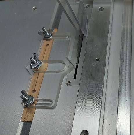
Does the thumb screw on the end of the post move at all with the passing of multiple strips over time? Your and Michael's design has some merit to it. My posting #1277 (8 JAN 22) in my build log shows an image with drawings I made. I'd be happy to send you a PDF copy. Kurt says the NRG are looking at selling a simplified version (mine was a combination of his and John's versions) sometime soon.... he is getting pricing for the bits and pieces. If I were to do mine again I'd likely make it at least 1/4" wider.
-
my thin strip jig or thickness guide setup on my Byrnes tablesaw (with thanks to Kurt Van Dam and John Garnish) I set the point distance from the blade with setup blocks Test cut and mic the thickness I can fine tune the thickness cut with the Byrnes micrometer setup
-
There are always multiple ways to skin the proverbial cat, and so, that is why we need people like Druxey following... to highlight the forest for the trees.
-
I will post the one image showing the sheave in use later this morning when the noise of the scanner will not wake up Her Majesty. Also, I just sent you a PM regarding the other information. Alan
-
Managed to sand all the chocks flush to the timbers this afternoon. Started fairing! (oh joy)
-
Sorry, I assumed most vessels from the late 1700's through the 1800's would be rigged somewhat similarly so all sailors would be familiar with it regardless what ship they transferred to. I am probably wrong. I did not expect you to have the books I mentioned in your library, hence I asked if any information I had mentioned was of any interest to you. I understand it is not. I hope someone knowledgeable steps up and you find what you are looking for! Good luck Commander.
-
The Fully Framed Model by David Antscherl (Swan class Sloop) has these sheaves. Modelling the Brig-of-war "Irene" by E W Petrejus does not show any. The Brig Niagara (on Lake Erie) does not have these.
-
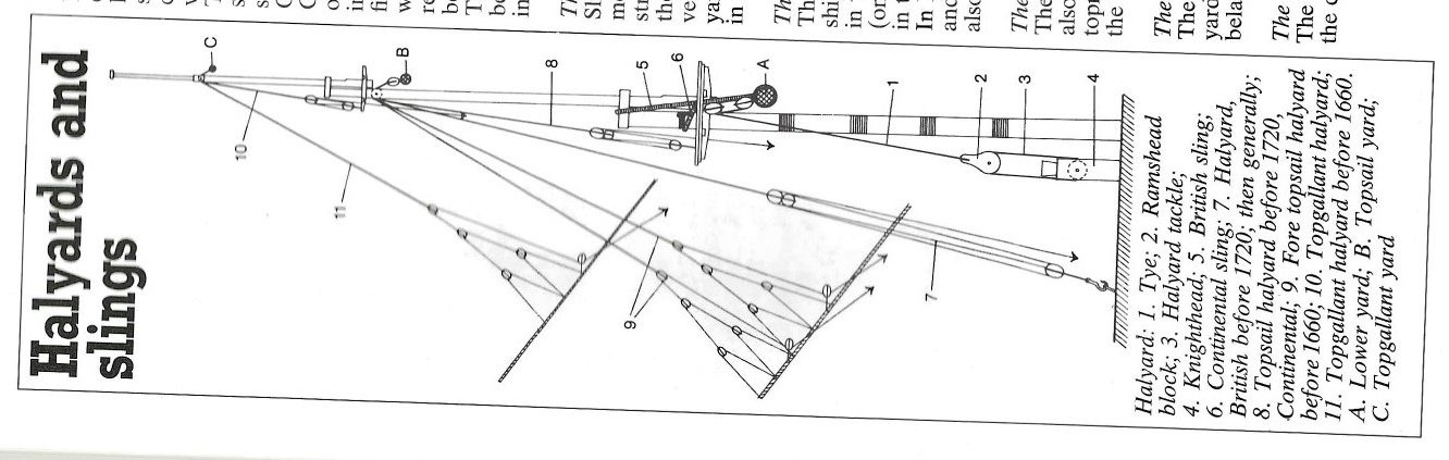
Have you Harold Underhill's "Masting and Rigging the Clipper Ship & Ocean Carrier" ? Fold out Plate 51 (pages 281 through 290) show all 135 belaying points for all lines. But I have not noticed any details on fife rail sheaves. Edward Hobbs' " How to make Clipper Ship Models" has very informative fold out standing and running rigging plates (III & IV) But once again nothing noticed regarding fife rail sheaves. Wolfram zu Mondfeld's "Historic Ship Models" pg 310 has a figure showing the lowest heaviest yard halyard running down to a ramshead block where it and the sheave in the fife rail act as a block and tackle system to provide additional mechanical advantage to raise/lower the yard. Are an of these of interest to you?
-
Today I completed the installation of chocks between the frames. Tomorrow I will sand them down to the frames and remark all gunports carefully before beginning cutting out the frames to install the upper and lower sills (cills).
-
Thank you for posting these. Very interesting. I never knew they were soaked, heated and widened.
-
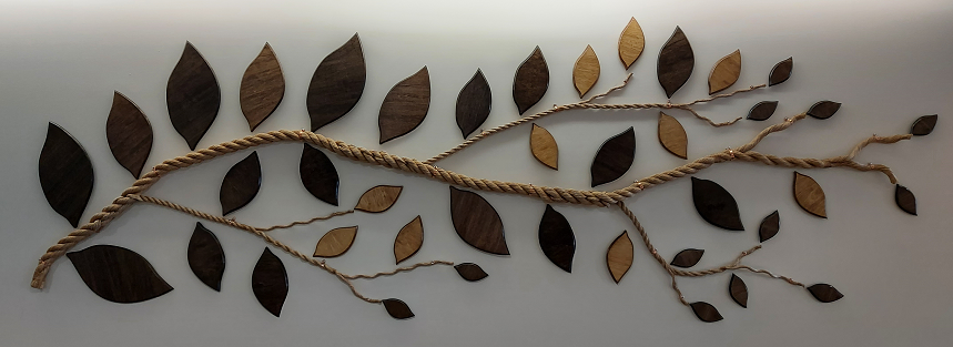
Another project completed.... the Donor Wall display for the local library. Now they just need to start collecting donations so they can add plaques to the leaves.
-
Yes and yes. I do not intend to handle them anymore then necessary. But damn they do look good!
-
Received my swivel guns today! OMG they are tiny.... and so sweet. (3D resin printed from my CAD model .stl file by a local club member)

-
Some day I will want to make one at 1:64 scale so I am all eyes

-
think having your stock lay flat beats every other option
-
Ropewalk: A Cordage Engineer's Journey Through History
AON replied to BenD's topic in Nautical/Naval History
It is interesting for the purist to note that none of the ropes are BLACK or WHITE. Even the 4 strand tarred rope is not BLACK. -
and the journey begins.
-
As a sea cadet we said Bell-air-a-fon. But a crusty old RCN (ex RN) Commander once corrected us saying it was Bell-er-o-fon just like it is spelt. I am sure the Greeks have the proper pronunciation.
-
Thank you Druxey. I believe I tapered the stem from keel to knee per the dimensions in the contract but that was some time ago so it is worth checking again.
-
The Fully Framed Model (6th Rate), vol 4, pg 44 - served all over The Anatomy of Nelson's Ships (1st Rate), pg 226 - seized at the bight at the heart and another at the foreside of the hole at the in the knee and a third at half span between the other two. Historic Ship Models, pg 276 - the two parts were seized together in several places