
HOLIDAY DONATION DRIVE - SUPPORT MSW - DO YOUR PART TO KEEP THIS GREAT FORUM GOING! (89 donations so far out of 49,000 members - C'mon guys!)
×


AON
-
Posts
2,867 -
Joined
-
Last visited
Content Type
Profiles
Forums
Gallery
Events
Everything posted by AON
-
 temporary spacers!?!? of course not. Once I had all the aft and dead flat frames in I was going to check the fairness and make adjustments, then put in permanent chocks near the head of the top timbers, above and below the chocks where I can, and above and below each gun port location to lock everything before sanding inboard and outboard. That should only take me forever and two days since I operate at the speed of dark. 😁 .... temporary spacers .... 🤔 hmmmmm. there is a simple answer for everything.
 -
I find that as I approach the dead flat, with frames fore and aft installed, the gap closes in and my hands are a determent to the available open or clear space! Broke one set frame removing my hand yesterday. Fixing that was fun. 😶
-
Were can I get this clamping device
AON replied to Cablejim's topic in Modeling tools and Workshop Equipment
cablejim I cannot see the image, only the path to your android device. could you please re-post it Thanks -
This will be one gorgeous finished model some day soon!
-
Join the meeting on Sunday at 1:15 and you can ask him directly. I have silkspan here and my sail I made at the seminar that I can show you. I can drive over and you can look at it at a safe distance from me in your driveway. Just give me a date and time. The material reminds me of what they use for teabags and is more appropriate for the reduced scale.
-
Paint job looks great. I have no idea about linen sails. I was taught to use silkspan and acrylic paint by David Antscherl at a workshop he did a number of years ago.
-
Now that I can see the difference, rotating it was the second dumbest thing I've suggested today. The first is between me and the wife... we'll let that one lie, collect dust, and be forgotten.
-
The wood filler and paint will look like a million dollar job! Can't you just rotate the steering box 180°.
-
Derek, I just tell myself what that masters do is all smoke and mirrors... then I try. Sometimes after a day or two I convince myself I can do better and try again. Usually I am right. Possibly because I learnt something valuable the first time and after pondering on it for that day or two I envisioned what I might try the second time. I believe that drive to try again is what made those masters. Never give up and don't sell yourself short. We all have it in us if we just try.
-
Nice to see you getting back to your Bluenose Derek! Hope to see some photos in the coming weeks. See you at the club Zoom meeting on the 12th.
-
Where did you get those spring clamps? They look very useful.
- 321 replies
-
- 5
-

-

-
- Finished
- Flower-class
- (and 1 more)
-
Excellent video as always! However you gave me a fright having your fingers that close to the cutting blade! Might I suggest you consider a small piece of wood with a lip on it to hold the item down and will allow you to push the item to to fence at the same time. I put a dowel handle extension (goes 90° to the fence) on my tool. I almost lost a finger when the wood I was cutting flipped over and pulled my hand into the blade. Now my hands never get near the blade.
-
I just used similar rotary cutters for my figurehead. My rotary driver was my 25 year old Dremel tool and flex cable. The cable needs to be disassembled occasionally and greased. You need to keep control of the tool as it sometimes wants to climb away! So take small controlled bites off the work. I found the cutters with spaces between flutes removed material best. Smaller regular dremel style cutters worked great for tiny bites. I recommend them, but keep your scalpel, carving knives and micro chisels at the ready. It was my first successful time using them...as I just got the proper (spaced flute) cutter set. Prior to that it was a mess... for me. Others seem to have no problem.
-
Thank you Druxey. I was told to do the heads first and that was indeed the most difficult part. I kept going away and coming back to it. Taking off a little here and a little there. Even when I thought I was done I kept going back to them. They are not in anyway masterpieces but from 1 foot away they are okay. This was not my first attempt. I've been at this on and off for almost 3 years. I suppose "on and off" should be my motto. There is one local fellow I could have commissioned and it would be a masterpiece but then it wouldn't be mine.
-
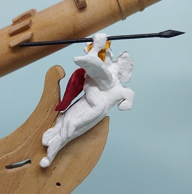
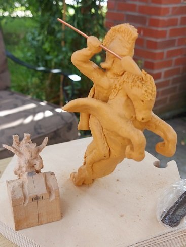
This is the result of my efforts in recreating my interpretation of the description of the first figurehead that was destroyed in 1793 when she collided with HMS Majestic in a gale force storm. I am quite happy with it and do not believe there is another model of this ship in existence with this version of this famous ship's figurehead. I hope I've done it justice. WOOD: Block of Linden bass wood TOOLS: Rotary cutters, Dremel rotary tool with flex cable, carving knives, miniature chisels, scalpel, and various sand paper (80 Grit to Super Fine). FINISH PRIMER: Javelin - Black permanent marker Remainder - Waterbase Folkart GESSO Surface Prep WHITE: Bodies - Craft Smart White Acrylic Paint RED: Cloak - Craftsmart Cherry Cobbler Acrylic Paint GOLD: Helmet - Kingart Metallic Acrylic Gold BLACK: Javelin - Craft Smart Black Acrylic Paint SEALER: Everything - KRYLON Low Odour Clear Matte Spray Finish
-
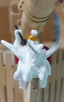
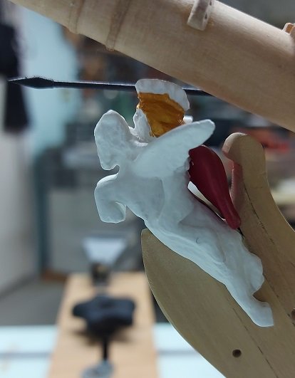
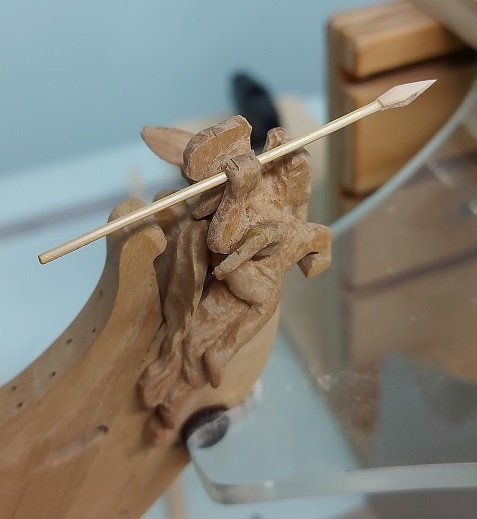
last images before it is painted
-
Made the javelin and the cloak. The javelin head is glued to the shaft. I notched the head (a 1/8" diameter dowel) and stepped the shaft into it with glue. When dried I shaped the head with a file and sand paper, having filled the notch with glue so the dust might fill the small notch. The cloak was shaped and fitted a dozen times and is now glued and clamped. I also glued the tip of the wing back on. From a distance it all look darn good to me... though I'm not particularly thrilled with Bellerophon's or the Pegusus' head up close. Regarding painting most of the figurehead features white... it wasn't until 1814 that the Navy Board approved the use of gilding and colours for figureheads. (source: http://figureheads.ukmcs.org.uk/?p=1715)
-
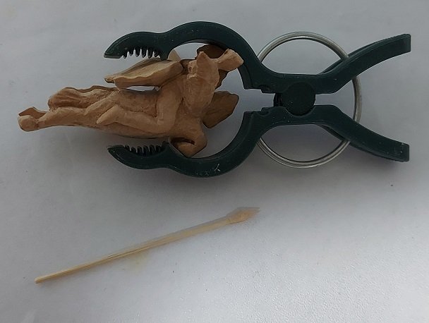
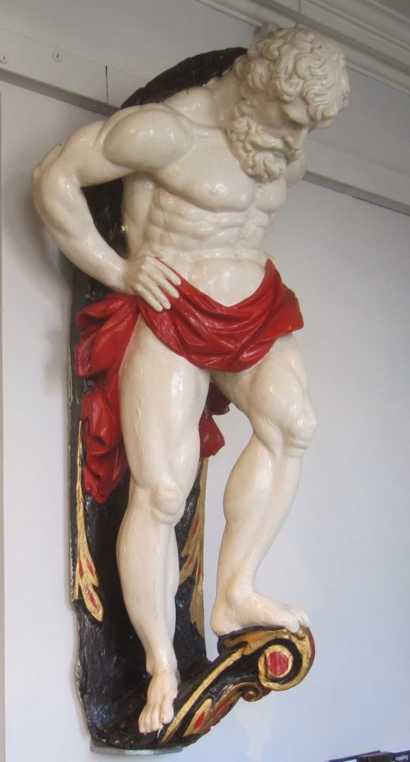
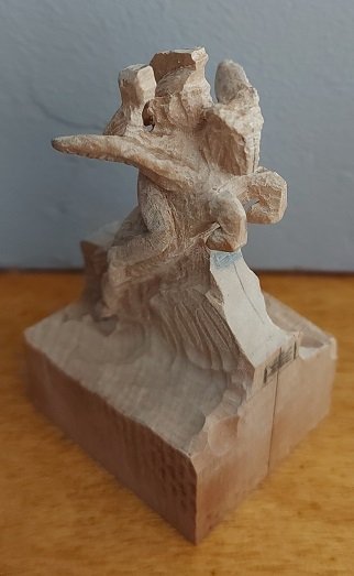
She has been cut free and is presently being fitted. Almost there! Once I have that done I will do a bit more sanding, add the cloak (because I'll have a better feel of the space left), re-attach the tip of the right wing that broke off, make the javelin (hole already in the hand for it) and paint it. Then it goes into storage for safe keeping. RE: Painting. Golden helmet with white plumes, and a red cloak. I understand everything else was simply painted white. Somewhat like the Atlas carving saved from the Captain's stern gallery as seen below.
-
On this side of the peninsula we call that *** backwards. For a micro second I thought my horse was backwards??? I understand what your saying and have seen photos of this. Let's see how I manage.
-
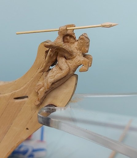
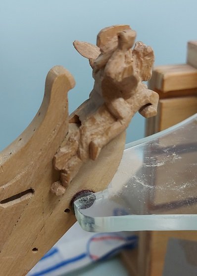
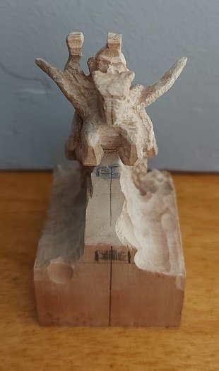
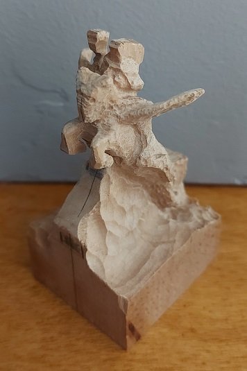
We had a couple of absolutely gorgeous days here in the Niagara Peninsula so I decided to take some work outside... and make another attempt at my interpretation of the original figurehead. Below are a few rough carved photos. It needs considerable cleaning up but looks good so far.
-
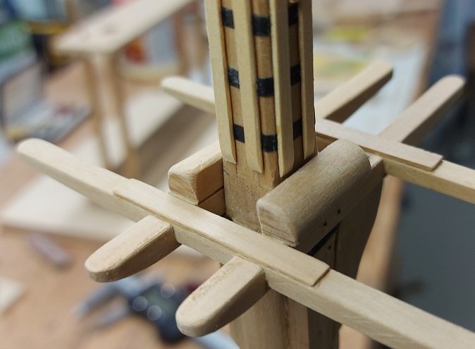
Took another look at my Iron Bars and decided they are keepers, so I won't be replacing them. However, I did notice something missing on my mast.... the LUBBERS WOOD! These are 1-1/2" thick planks installed on top of each Cross Tree and they fit inside the Lubbers Hole in the TOP. As they will help self centre the TOP onto the TREES when it does get permanently installed I decided to add them today.
-
Thanks. I'm not sure if I will redo the card stock iron bars.... I put them away so I can look at them fresh next week or so.


