
HOLIDAY DONATION DRIVE - SUPPORT MSW - DO YOUR PART TO KEEP THIS GREAT FORUM GOING! (89 donations so far out of 49,000 members - C'mon guys!)
×


AON
-
Posts
2,867 -
Joined
-
Last visited
Content Type
Profiles
Forums
Gallery
Events
Everything posted by AON
-
 Thanks Don All I need now is some bad weather so I can lock myself downstairs with the ship and not feel like I am missing another beautiful day.
 -
Although embarrassing it is human error, mine and the original draughtsman. I never thought to blame the measuring tape. I have to say your suggestion to make rulers to my build scale has been unbelievable worthwhile!
-
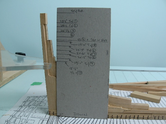
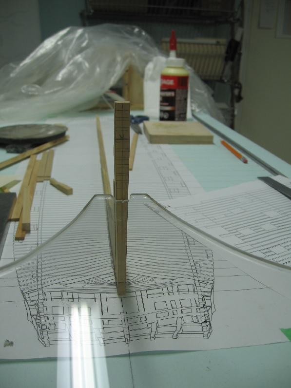
Sunday 02 July 2016 Some time has passed since my last posting here because I had revealed yet another issue. Druxey had commented that I should assure I get the wing transom set at the proper angle or everything would be thrown off. When setting the angle something seemed amiss. Upon studying the original sheer and timber plans from NMM it became obvious they did not agree with regards to the placement of the transom pieces. To add to this my stern post was short by almost two feet (my error). After considerable reflection I marked the proper heights on a piece of stiff cardboard. I cut off the top of my stern post to be flush with the upper side of the wing transom and then grafted an extension to my stern post to be the correct height. This has yet to be sanded. I then had to adjust the height "shelf" of my inner post and nipped off all those wonderful pocket extensions. I am concerned for the adjacent frame templates now as they may be out of alignment. I'll be double checking this before I make these aft frame timbers. I've rough cut all the transom pieces and will fit them after I have the stem post assembly made and attached. I'll be working on the stem post next.

-
I find owning a house and summer time provide all the necessary distractions to avoid boredum. The grass continues to grow and cries to be cut. The sun shines beckoning me outside. More importantly..... the fish are jumping! When I finally get downstairs to find myself emersed with the model for hours everything is fresh and new again.
- 191 replies
-
- 1
-

-
- victory
- caldercraft
- (and 1 more)
-
Being in mechanical engineering I found this last exchange quite intriguing! Thank you Druxey for explaining why (some or most) knees we installed with bolts in sheer as until you stated the obvious "ease of repair" reason I was swayed to the logical "mechanical strength of design" explanation. I hesitated to respond earlier because you are no rookie... even though all the evidence was stacking up against you (photos and figures and mechanical design logic). Now I understand why they were installed on the side in most builds... and as in life some will be different (diversity) for whatever reason.
- 649 replies
-
- 6
-
-
- dunbrody
- famine ship
- (and 2 more)
-
Good morning Don, As an old (old OLD) draughtsman I have almost a complete set of leads for my really ancient mechanical pencils. The hard leads do keep a point longer but they were meant for light line work (layout work not object lines) and, for me, do not always leave a easily visible line on wood. The softer lead does leave an easily visible line without gouging (engraving into) the wood. I believe I mentioned this before... I am naturally very heavy with my pencil work so must be conscious when using one so I do not leave a permanent dent behind. The softer lead works better for me personally. The newer thin lead mechanical pencils do not like me so much... the lead keeps snapping off (breaking) due to my natural tendency to put to much pressure on them! Alan
-
Understood. I've been thinking about building an adjustable device to allow me to set the transom (height) in position when gluing. I'll keep your advice in mind.
-
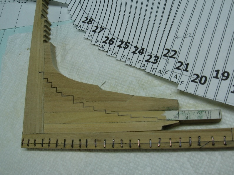
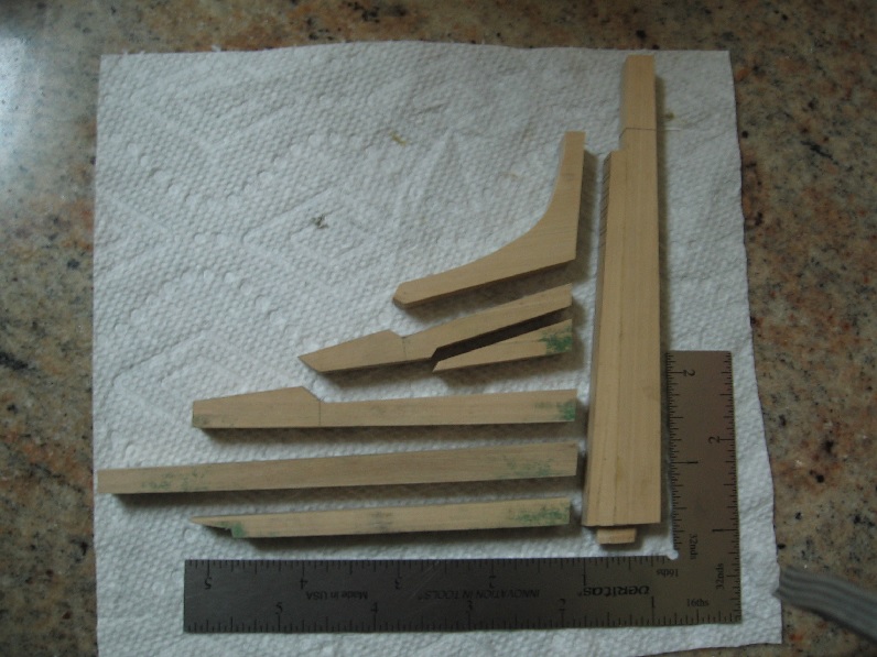
It was brought to my attention that my Wing Transom might not be set at the proper angle. It was above horizontal (rising) inboard. Thank you Druxey. You can see from the snip below that they wing transom should be ever so slightly below horizontal inboard on the top surface. The lower surface is tapered. The next two below it are also to be set so the top surface is lower inboard. I made a small corrected the relief cut in the stern post to fix the issue. Presently the (upper most) Wing Transom is now horizontal. Another ever so tiny correction is in order, then I must correct the Filler Transom. The next two lower transom template pieces are glued and ready for cutting.

-
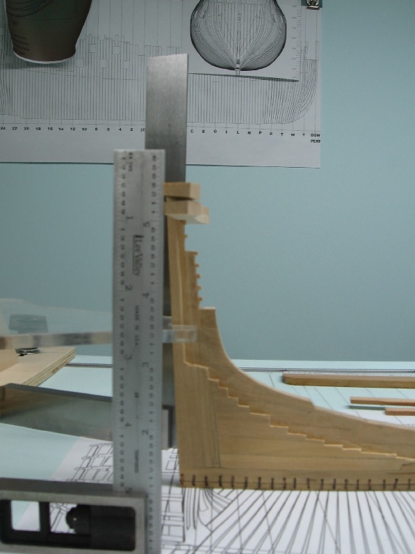
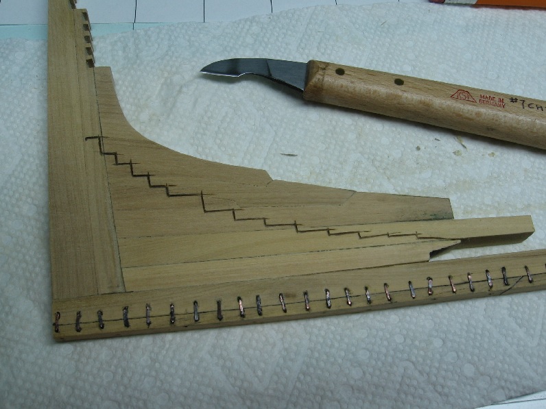
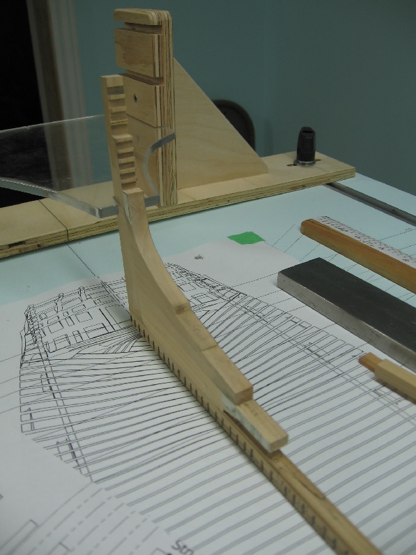
June 11 2016 I cut the frame steps into the port side of the aft deadwood and installed two more sections of the rising wood... and yes those are the two upper most transom pieces dry fitted into place. The Wing Transom and the Filler Transom. I intend to cut the other transom pieces but will not be fixing them in place permanently until I get the Stem Post (at the pointy end as my darling wife refers to it) in place.


-
The lighting certainly changed things considerably! Might be just my bad eye sight but the bamboo doesn't seem quite right does it. The top middle castello looks nice.
- 968 replies
-
- 4
-
-
- hahn
- oliver cromwell
- (and 1 more)
-
Good morning Druxey! I had tried a very thin lead mechanical pencil, running it along the edge of the paper template but it did not work very well. So I used a regular old fashion wooden HB pencil with a dull point and ran it over the paper template and edge. I figured it would leave a crisp line at the edge of the paper and I would cut the step along the top edge of the line. My hand wasn't that steady but none the less I was quite happy with my first ever attempt. A.
-
Thank you all for the likes and comments. I slept on it and decided to do the other side exactly the same. "Two wrongs do not make a right" but in this case they will simplify the task as cutting the small relief notches in the sides for the (upper) transoms would very likely have resulted in one or more of them chipping off. My original plan was to leave them out completely. l likely would have tried anyway just because they are supposed to be there and so may have subconsciously did what I did as a result... more excuses! Decision made.
-
Worked on the aft frame steps in the deadwood and stern post. Finished one side with an error realised at the end... I went too high up on the stern post. (I thought I was being so careful) Now I must sleep on how to fix it... I have a couple ideas in mind.

-
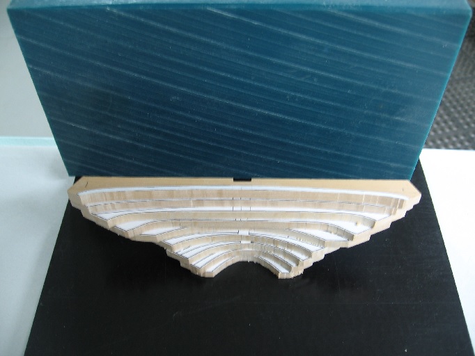
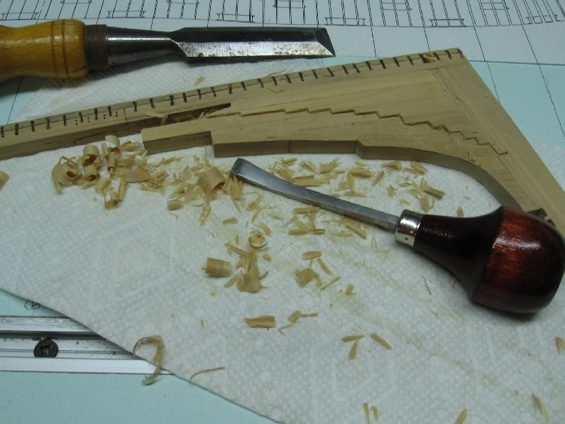
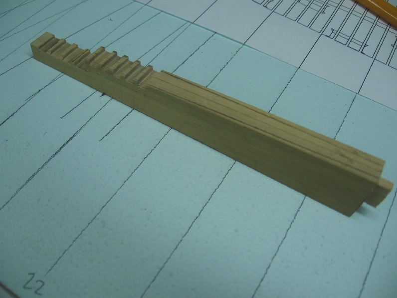
June 5 2016 I marked off the various transom steps into the stern post. Sawed down to the reasonably proper depth (3/32" or 6") then made a number of cuts between, chiselled out the pieces and filed flat and square. I then cut out a template of the stern frames in side view and laid it over the dry assembly of the deadwood and stern post. Some guide pencil marks were made on the wood but I did trace the wood assembly onto the template so I can properly lay it over again and trace the steps onto the wood. The taper was marked onto the deadwood and the stern post was sanded to the line while the deadwood assembly was sanded down to just outside the line. Presently all is glued together to the keel and set to dry. Once dry I will finish the sanding and trace the step locations onto both sides of the deadwood then cut this in.

-
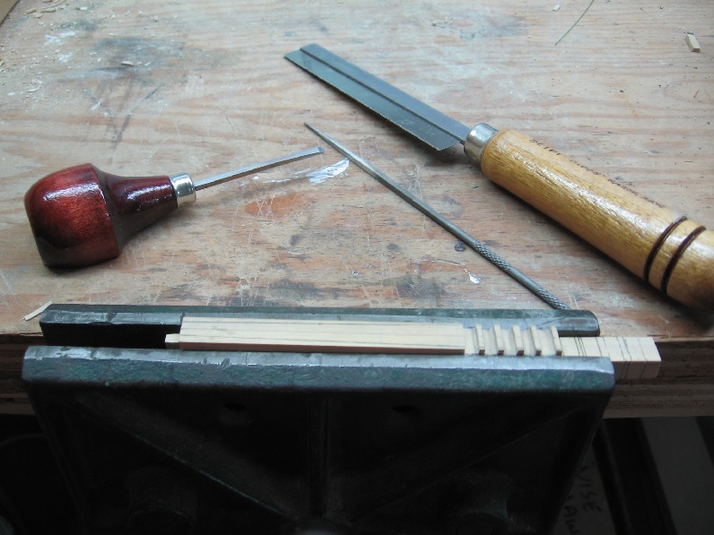
Thank you for the likes and encouragement in this small step. I found that practically every piece was off on one side, top and bottom, by a hair. The accumulated error over the six parts was considerable. I checked the table on my sander and it seems as square as I will ever manage to set it. I've 2-1/2 years to go before I retire... that must be the secret except my retired friends tell me they've never been so busy!
-
Saturday 04 June 2016 I managed to sand things relatively square and glue them back together. The good news is I didn't have to remake any parts. I will try to find time to sand to shape and mark off the frame footing steps tomorrow. As a side note... I do not know how everyone else manages to get so much done in a week. My days are just too full!


-
you do not want to drink that stuff... causes hair loss, blindness and a shortened life span.
-
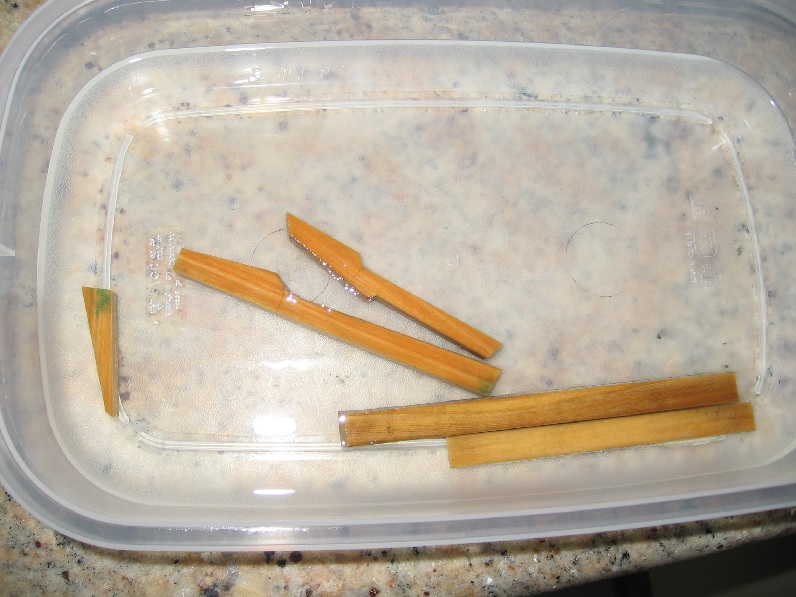
Thank you for the suggestion Mark. The likelihood of a next time is very strong. Alcohol soak towels or soaking in tub, either way I was very impressed by the holding power of the glued joints.
-
Wednesday 01 JUN 2016 Went through a couple of sunny outside weekends, Victoria Day weekend and this last one (I took a couple days off so it was extended) and got the outside gardens and yard in order for the summer months. Went back to my deadwood assembly to start work this weekend and noticed there was a wee (curve or curl) in it. One, possibly two of the joined edges are not quite square. I thought of this as a minor set back but it proved to be otherwise. Tried to lay out the shape to be removed to see if it mattered and it was just too close to call so I had to take it apart. What a nightmare! Try to unglue one piece in the middle. As the wood soaked up the alcohol I felt my other joints would be compromised so it all had to come apart. After two days of soaking in a wrapping of alcohol soaked paper towels and that wrapped in plastic wrap it still wouldn't come apart. I ended up clamping it just below a joint in my wood vice and wiggling it side to side until the joint broke and then the exposed glue joint was seen to not have dissolved completely. I had to soak the pieces for a couple hours to soften it adequately to scrape off. Some surface discolouration but that will sand away. Now it is clean, dry, and ready to be fixed. Now I am off to work as my long weekend (vacation) is over.
-
I wish I knew enough to help with an intelligent suggestion ... but I am one of the students
- 649 replies
-
- 6
-
-
- dunbrody
- famine ship
- (and 2 more)
-
tons of sun and heat over here to early after winter to complain yet
- 1,616 replies
-
- 4
-
-
- caldercraft
- agamemnon
- (and 1 more)
-
If ever you find yourself feeling a bit beat up with the errors and do overs just consider the wealth of knowledge you are passing on. Thank you for the lessons!
- 649 replies
-
- 6
-
-
- dunbrody
- famine ship
- (and 2 more)