HOLIDAY DONATION DRIVE - SUPPORT MSW - DO YOUR PART TO KEEP THIS GREAT FORUM GOING! (89 donations so far out of 49,000 members - C'mon guys!)
×


AON
-
Posts
2,867 -
Joined
-
Last visited
Content Type
Profiles
Forums
Gallery
Events
Everything posted by AON
-
 An actual miniature eye splice... I've dreamt of doing this but having made many a splice in real life lines of various sizes with fingers, feet, fig and spike I have a feeling it will remain in my dreams My copy of The Masting and Rigging of English Ships of War 1625-1860 by James Lee covers quite a bit of this. The diagrams are very helpful but when then don't exist the verbage needs re-reading multiple times before I can start to make some sense of it. If you need anything from it in particular just ask and I'll be there for you. I'll look at the section for the bowsprit rigging tonight and then PM info to you. Yes, if you are offering a copy of the photos I am gathering everything I can to help me with my build. Time for me to get off to work.
 -
Why thank you. It must be one of the side effects of smoking a pipe. The same thing happens when you drink too many tots of rum and then look in the mirror. I am happy to have helped. Your rigging photos are my cheat sheets for 5 years from now.
-
I will PM you what I have.
-
Thank you Mark and Druxey. Re: the nuts.... the are very manly.
-
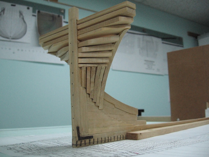
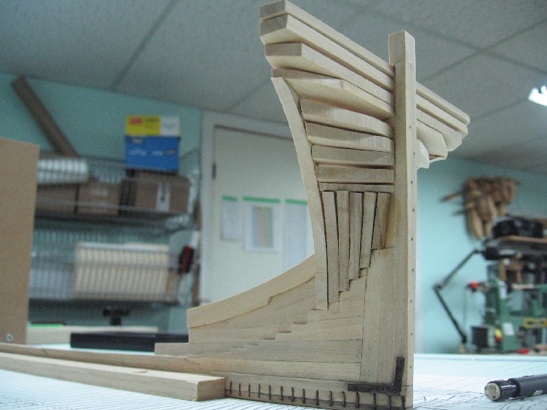
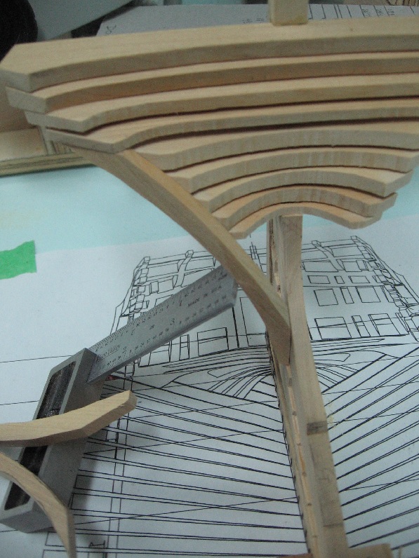
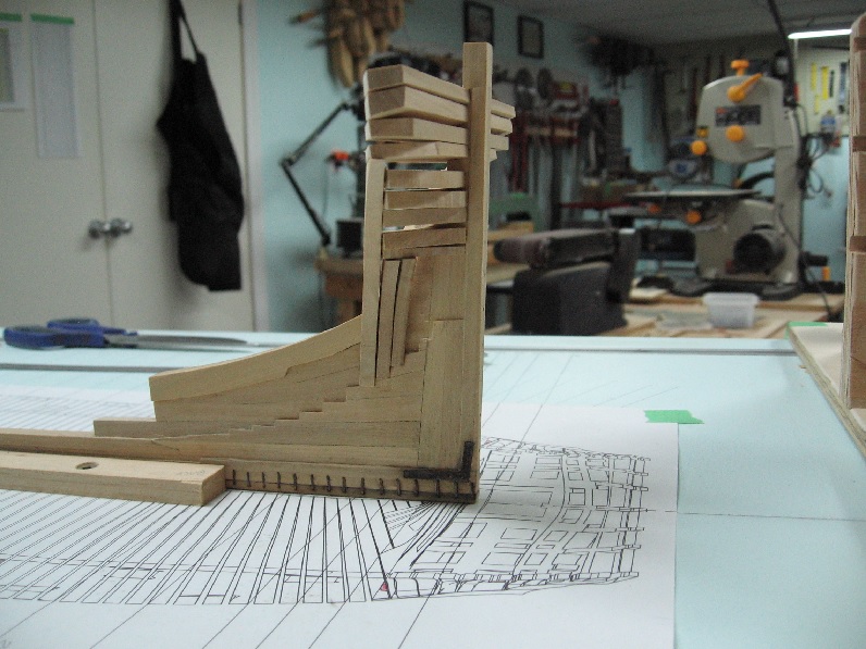
Sunday 16 Oct 2016 Some minor progress. This is much harder than it seems. I hope to be better at framing soon.


-
I wouldn't dream of telling you how to do it. You keep on experimenting and reporting and I'll keep learning!
- 649 replies
-
- 6
-

-
- dunbrody
- famine ship
- (and 2 more)
-
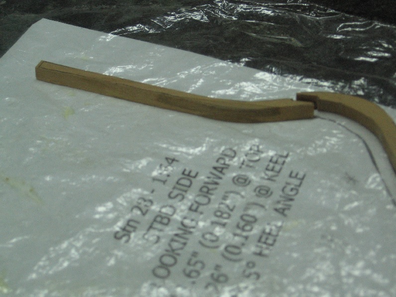
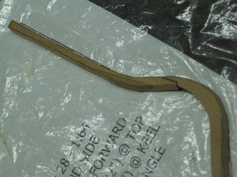
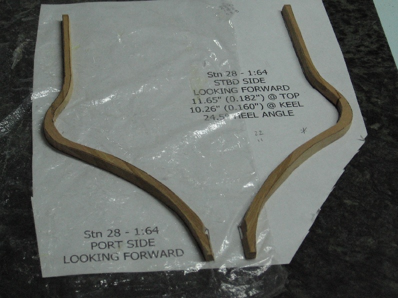
Monday 10 Oct 2016 Leave it to a Theatrical fellow to (almost) quote George Shaw. I think I almost do Druxey... the tutorial earlier in the year didn't hurt much. In fact it certainly helped today. I tackled Frames 28... after having woken up to +2°C and decided I best close the water fountain off the patio, drain the garden hoses and blow out the sprinkler system this morning. It may be early but if I wait much longer it will only get colder and less enjoyable to do. I bevelled the scarph joint... in the correct direction (almost screwed it up). I also left the overall length about 8" (1/8" or 3mm) proud at the top (head). I will put it up tonight or tomorrow. I want to let the glue dry thoroughly as I still need to taper the thickness slightly. Should mention I did each of these individually and then when almost done I remembered Druxey's trick off gluing two pieces of wood together (rubber glue) and cutting in pairs to save time. I will try this next time!
-
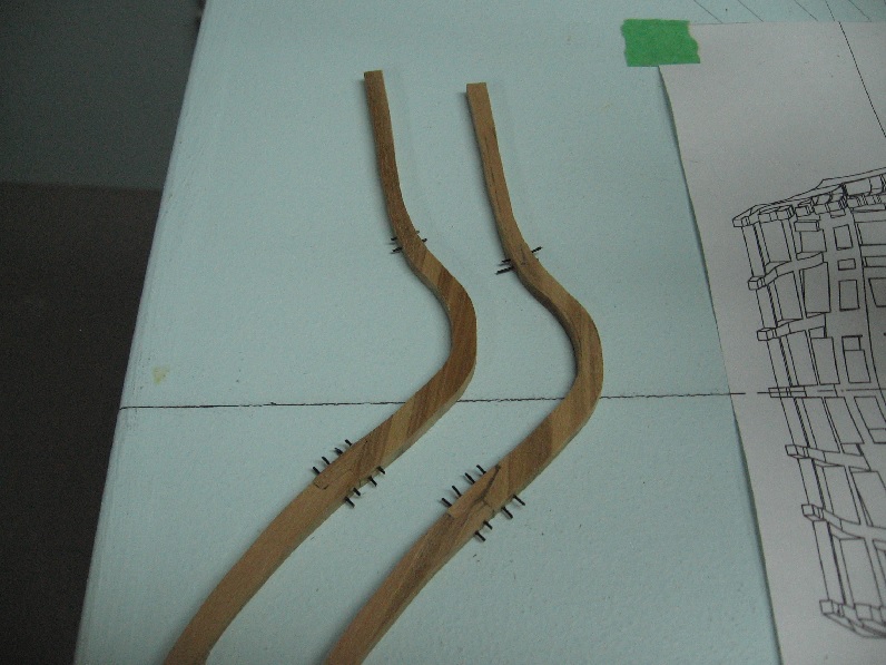
Sunday 9 Oct 2016 I did manage to steal a few hours for myself (between peeling potatoes and washing dishes... and eating... Happy Thanksgiving to all fellow Canuks out there) to complete the last group of three pairs of short cant frames. There were three scrapped pieces and a fourth that flew away from me from the sanding belt. I searched for it for about 10 minutes and finally gave up and cut out a new piece. As I turned around to go back to the other end of the room I saw it in the chippings on the floor around the planer. I made a new piece and as it was better I threw the old one out. I have a magnifying glass attached to my scroll saw table to help me focus on my cuts. I find it helps tremendously as I also have early stages of macular degeneration in my left eye and it plays havoc with lines. Here are some photos. Going to try frame 28 today. It is a long one with one bevelled joint.


-
How many left to go? I would think just enough to make me a pro... at at least extremely competent. Today my son and daughter will be over for our thankgiving day dinner. TGD in Canada is actually tommorrow but when everyone has other plans you adapt.

-
Saturday 08 OCT 2016 It took me three tries but the third was the charm. The secret seems to be measure 50 times and cut minuscule slices and sand microscopic bits off until it fits. Following that rule of thumb the others worked out fine! Had to stop after three sets as my upper back, between my shoulder blades is getting sore. It all relates to my neck fusion. I'll be good to go again after a short bit of rest.

-
Thank you for saying so. It is somewhat comforting to know I am no better than the best. I actually feel quite good about this first effort.... but if it is going to take three or more tries I may change my mind
-
Friday 07 OCT 2016 Made my very first frame today. Frame 28-Aft. A short frame that runs from the stern deadwood to the lower group of transom pieces. Turned out better than I thought it would... but it is scrap. Everything is perfect except for the fit of the foot to the dead wood which you can see in the photos. The head mates perfectly. The thickness tapers perfectly. It is just the fit down below. I can't even hide it under the keelson as it stops just before frame 28. Let's see what I can manage the second time, eh?

-
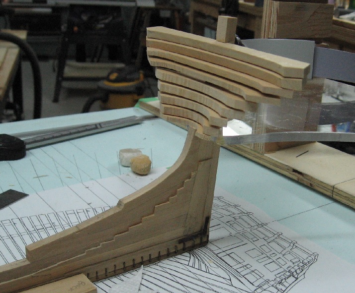
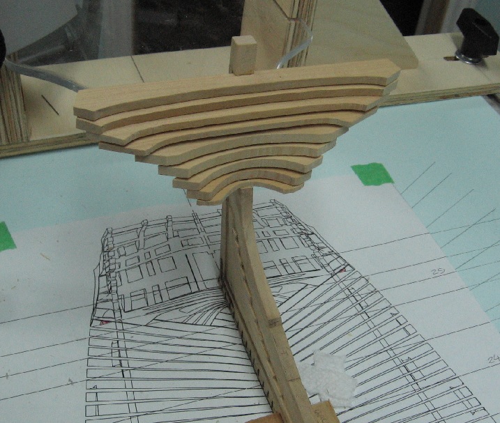
October 02 2016 I managed to glue all the transom pieces to the stern post this weekend. Notching the transom pieces to slide over the post was so tight that the glue was scraped off when sliding them together so I file a couple grooves on the sides of the transom piece notches to retain some glue when assembled. Doesn't look half bad and starting to look like a ship. I'l have to add a few more bolts to the stern post.
-
Good evening Mike. I have to agree with you on the scrapers. Your work looks amazing. Thank you for posting the info on the mini scrapers earlier. I have a full size set and from your posting info I found a place in Canada that didn't charge $50 for shipping $17 worth of merchandise. http://www.woodfrog.ca/default/woodworking/hand-tools/scraping/lynx-mini-scraper-set.html They are quite tiny!!!
- 968 replies
-
- 5
-
-
- hahn
- oliver cromwell
- (and 1 more)
-
After 3 years of mechanical draughting in high school (WH&VS... yeh Go Tigers!), having been exempted from Engineering Drawing in college, started working as a Junior Draughtsman in 1975.... that's 44 years before I figured out how to do it wrong! I'm going to blame it on computers... they are making us dumb.
-
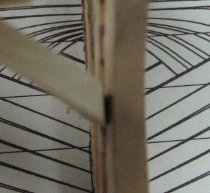
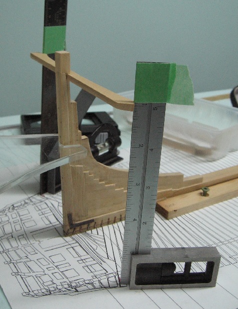
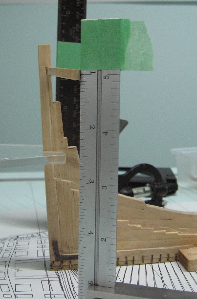
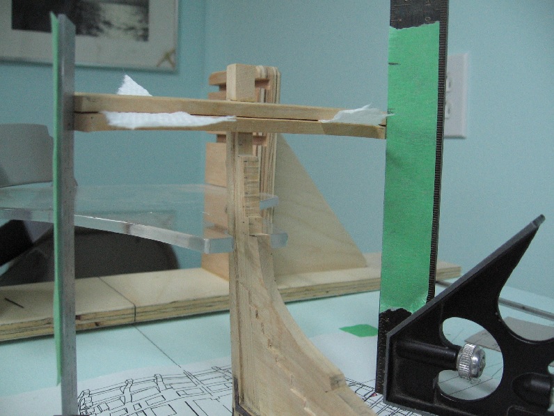
Reading the scale incorrectly was easier than I could have imagined. Using my 1/4" = 12" triangular scale I measured (something like) 26'-6" off the NMM plan print. Using my home made 1:64 scale I set the scale at the 6" mark and then marked off at 26' for a total of 26'-6" The first foot of the scale (where it starts at zero to 1' and is divided into inches) was skipped completely. I had actually transferred 25'-6". And that is how it is done! There is no such thing as a smart misteak. I understand regarding the paper towel comment. As the lower transom piece was set up and glued I simply needed to keep it from wobbling. There was no clamping pressure applied between it and the Wing Transom. The set squares were holding it in place When I checked it this morning it was perfect... the glue was set and I removed the paper. I'll try to make slivers of wood for spaces next time.
-
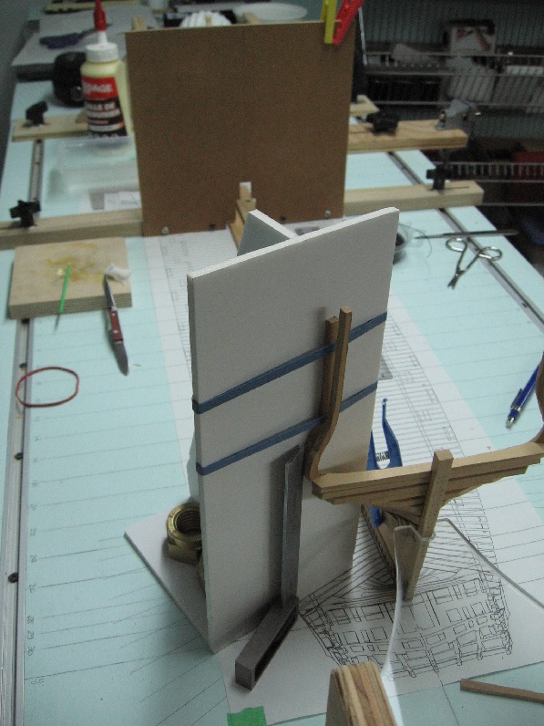
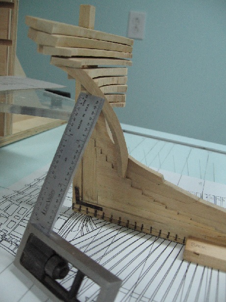
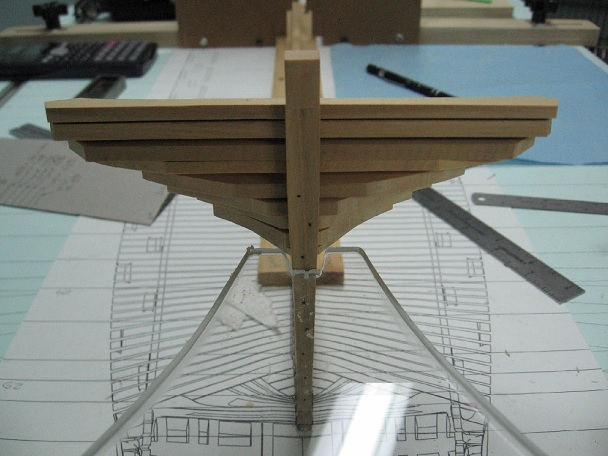
Sunday 25 Sep 2016 Suffered a minor heart attack today.... not really... but I was transferring measurements from my prints and they were all out by a foot! I nearly died. Then I realised I was reading the 1:64 scales incorrectly. After 40+ years experience I was reading scales incorrectly. What a dumb a$$ ! Then I remembered my stern post was short and thought HOLY CRAP I did it back then too. Double checked and I hadn't. That one was wrong. I must be tired I managed to attach the upper most wing transom and the one just below it. I had to make both twice before it was right. I also didn't use any fancy supports as they were more of a hindrance to my access than any help. I put a tick mark on tape affixed to my squares to get the height correctly (Not show is the cardboard card used to set the outboard height of the slanted transoms) The gap between the upper most wing transom and the next lower is about the thickness of my paper towels so that is what I used to maintain the gap.
-
Unique modification to the bulldog clip! I've got to jot that one down.
- 649 replies
-
- 5
-
-
- dunbrody
- famine ship
- (and 2 more)
-
Yes, I used LoS (Liver of sulphur) as before. This time was better but third time will be the charm.
-
Thank you Carl, There are likely a number of other ways it could have been handle and I am open to hearing them all. This is my first build since 1990-ish (second in my life) and is quite different from balsa wood and an exacto knife so I've a lot to learn. I acknowledge my "novice" level and expect to make a considerable number of errors. The learning curve is steep and I am a willing participant/student. As I get further along and find more time (I plan to retire in two years) I may begin again as I find I progress from novice to advanced beginner to competent and hopefully someday proficient! I do not think I'll have 40 years to become an expert. Then again as I progress I may quite like what I've accomplished and carry on. Every day is a new beginning. Please do continue to make suggestions.
-
I didn't do it before because I had to assemble the tiny bolts through the plates. The blackening is an oxidation process and so I feared the almost size for size holes/pins might not assemble after the fact. The "flange" or rolled edge created on the pins is tiny so the hole cannot be much more than it is or the pin will drop through. I thought of assembling them off the wood but was concerned about getting 6 or 7 pins to they align with the pre-drilled holes in the wood. If the pin went in wonky it wouldn't align. I could have drilled the holes in the wood larger than needed but then the pins would be loose in them. Could have put glue in the holes but 10 seconds is not a very long time to get it right. So doing what I did and having read on the forum that it does not affect the wood I felt it was the correct method.
-
Good morning Druxey, I value everything you suggest and so my GG will be banned to reattaching soles to shoes. I had read where others had blacked in place and so thought is was a good idea. I guess I shan't be doing that again.
-
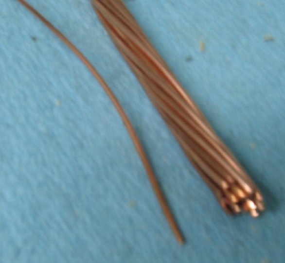
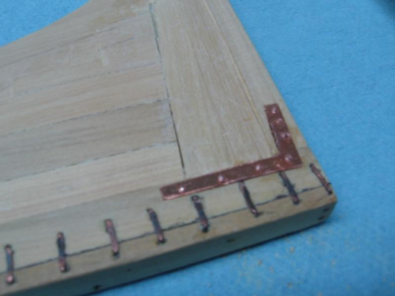
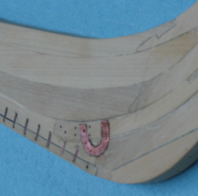
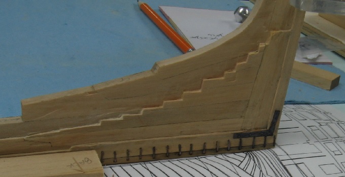
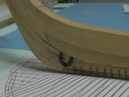
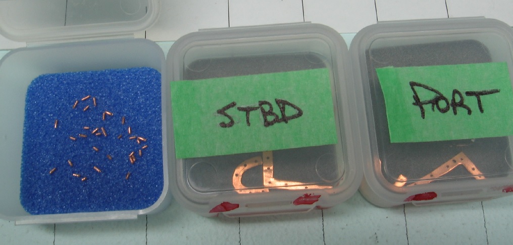
SEP 17 2016 Yesterday was a good day to work in the shop, raining all day with thunder later in the afternoon. I worked on finishing the installation of the brackets and horseshoes. First I had to make the bolts. I followed the method posted elsewhere on the forum ( Making nail s with rounded nail heads http://modelshipworld.com/index.php/topic/11204-tiny-fake-nailsnail-heads/?hl=%2Bbolt+%2Bhead#entry341045 ) I managed to acquire a short length of multi strand wire with strands measuring 0.031" diameter (1.98" to scale). The snipping created a burr that I tried to file off but what was left tended to help hold it in place. The rolled head was very tiny and barely noticeable but it was round and for the scale looked very good. I needed 26 bolts but made 30. I cleaned everything in white vinegar, rinsed in water and dried with a paper towel. Separated everything in clearly marked containers so I wouldn't try to put the port bracket on the starboard side (as the relief are cut to match the bracket). Wearing latex gloves the brackets and horseshoes were glued in place using Gorilla Glue (10 seconds time to work). Getting the bolts assembled with tweezers and my smallest hammer was a real treat. I mixed up a weaker batch of blackening agent and used a cotton swab to apply. Then, of course, disaster. Some glue must have seeped around an edge or through a bolt hole and the blackening was not over the whole assembly. I then spent considerable time re-cleaning in place and re blackening. The final outcome is not what I'd hoped for but it is not completely terrible (or am I trying to convince myself?). I've thought (all night) of removing them but any second item will not fit perfectly into the existing recesses and bolt holes will not align. I am going to have to stare at it a bit and decide if I can live with this, my second attempt at blackening.