HOLIDAY DONATION DRIVE - SUPPORT MSW - DO YOUR PART TO KEEP THIS GREAT FORUM GOING! (89 donations so far out of 49,000 members - C'mon guys!)
×


AON
-
Posts
2,868 -
Joined
-
Last visited
Content Type
Profiles
Forums
Gallery
Events
Everything posted by AON
-
 If ever you find yourself feeling a bit beat up with the errors and do overs just consider the wealth of knowledge you are passing on. Thank you for the lessons!
- 649 replies
-
- 6
-

-
- dunbrody
- famine ship
- (and 2 more)
-
... going over the side ... sounds like a job for a bos'ns chair and a bos'ns mate ... or Boatswain for those less familiar
- 3,618 replies
-
- 4
-
-
- young america
- clipper
- (and 1 more)
-
Magnificent picture perfect view. I cannot imagine rain or snow ruining it.
- 1,616 replies
-
- 4
-
-
- caldercraft
- agamemnon
- (and 1 more)
-
good eye robin!
-
Metric vs English
AON replied to jdiven's topic in Building, Framing, Planking and plating a ships hull and deck
And all this time I thought English was a language and Imperial was the system of measurement I find metric is easier but somehow I still screw it up. -
Now that is funny Druxey!! If I could make something that beautiful once... I would close the book! I hope you take another set of professional looking photos that match the magnificent work, pick the best, frame it and nail it to the wall (or silver solder it to the wall)... then blacken the original as you intended so we can continue to be amazed.
- 3,618 replies
-
- 7
-
-
- young america
- clipper
- (and 1 more)
-
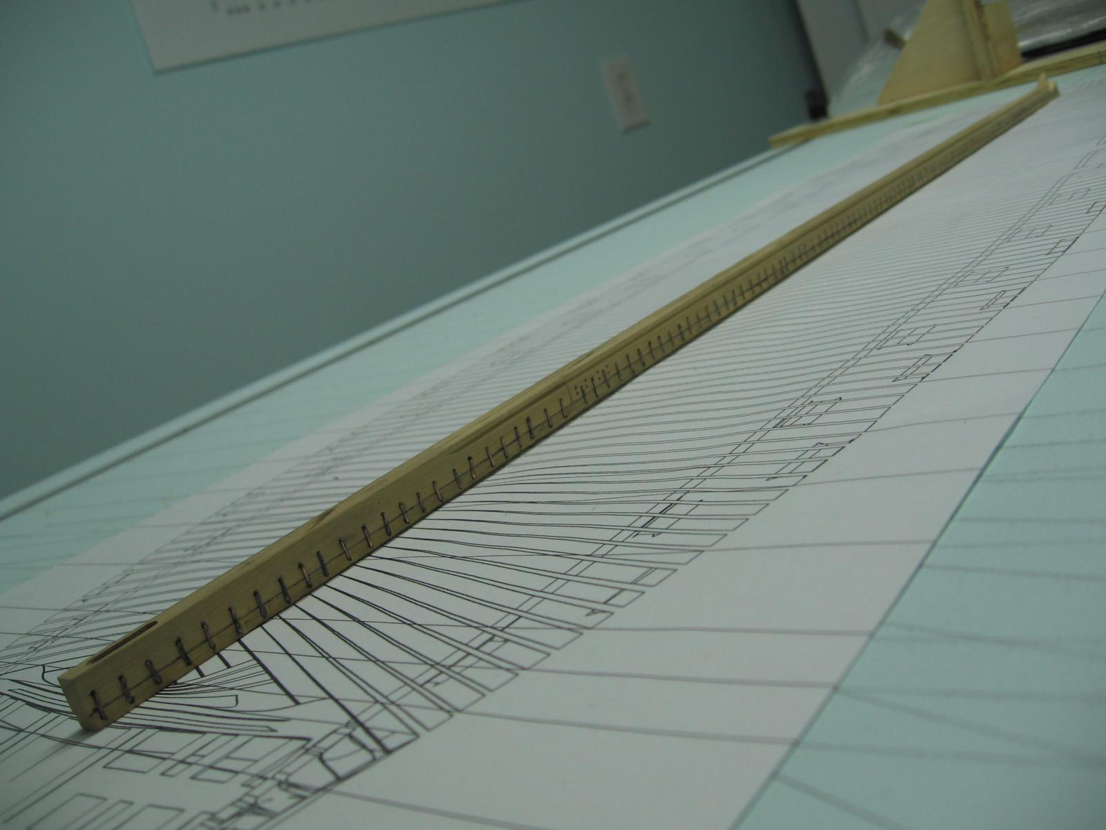
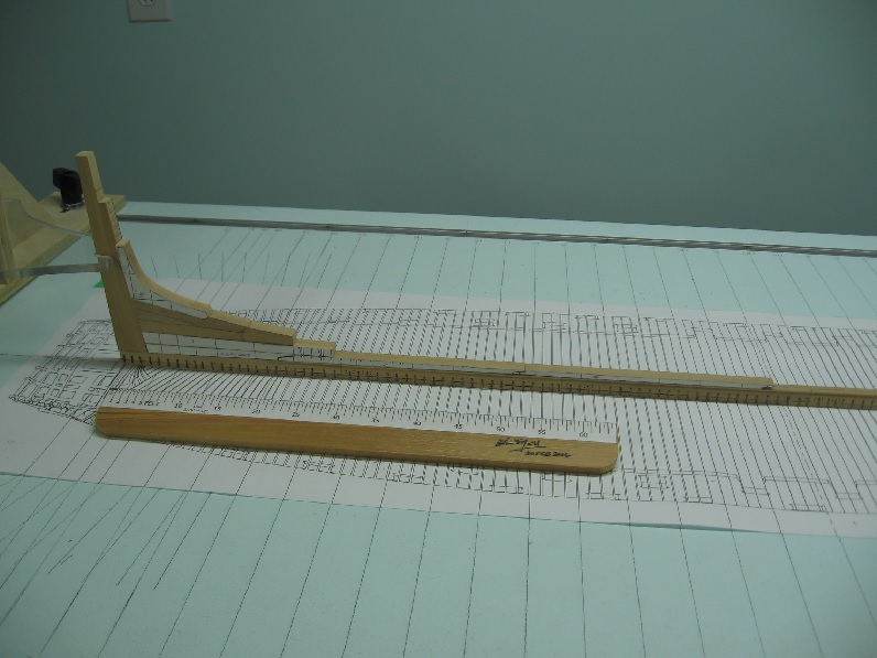
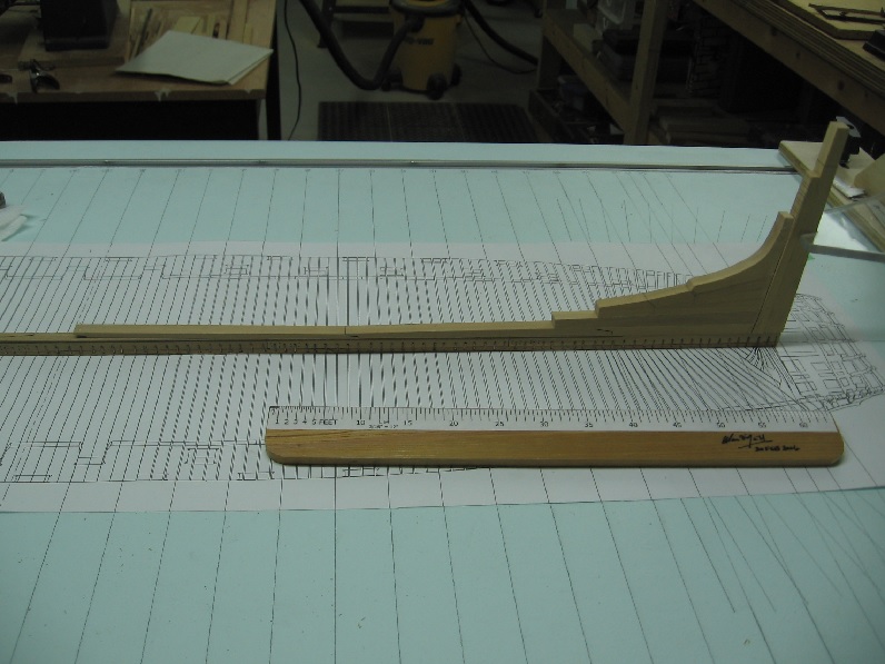
Saturday 14 MAY 2016 Worked on the aft rising wood , deadwood and knee. The rising wood is typically 22 inches wide except where the whole assembly tapers as it approaches the stern post. Glued the knee to the deadwood Glued the aft most rising wood section to the deadwood Sanded the deadwood assembly to the proper angle to mate with the stern post. Made the next two pieces of rising wood. Took a couple photos (port and starboard sides) of the pieces dry fitted to the keel. I have some fine tuning to do with some rising wood joints but thought I'd best walk away right now before I do Too much and regret it. Once I have these fitting a wee bit better I will taper the deadwood, mark off and cut in the frame heel steps. Then I think I will finish the shaping of the stern post assembly.
-
Thank you for the kind words and thought Robin. If only I felt deserving of them. Some people call it disciplined... I think of it as Irish stubbornness... I never ever quit. It is my one and only fault ...honestly As I mentioned it is early yet and I've many MANY more opportunities to screw up... I may need a bigger scrap bin!
-
Absolutely correct with regards to margin of error. I do not use a very sharp point with a hard lead and get a good consistent width line, but find that a soft lead ends up quite quickly being a wide line. As a draughtsman, early on, I use to carve my lines in the paper. I learnt to appreciate the different weights (hardness) of pencils or leads and sharpness. I do not miss the sanding blocks and graphite smudging everywhere.
-
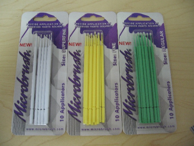
Thank you... but I've barely started. You don't want to swell my head too early in the game! The applicator is from a microbrush (see photo). Eventually the "brush" part is ruined and I pulled it off to reveal the fine tipped point which is what I use for spreading (and applying to extra small piece) the glue.
-
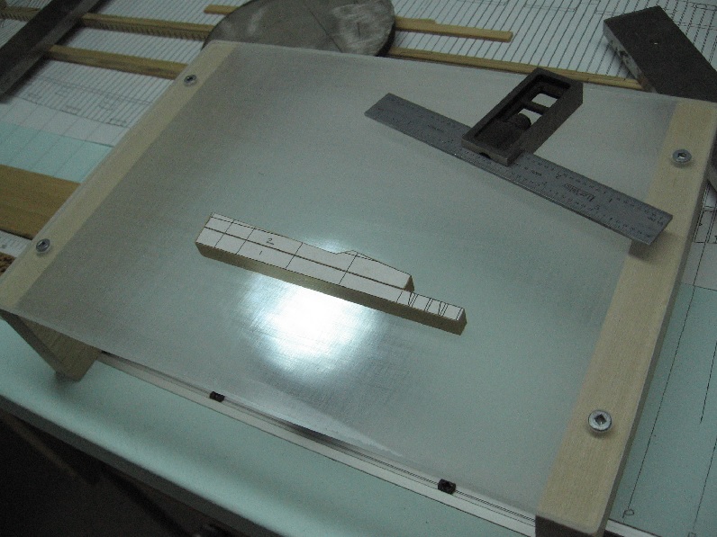
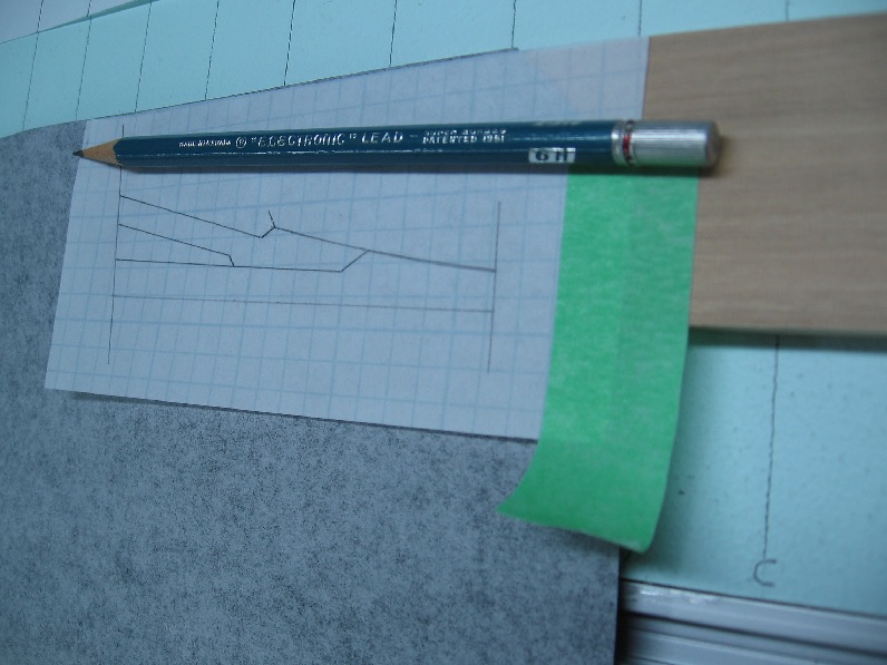
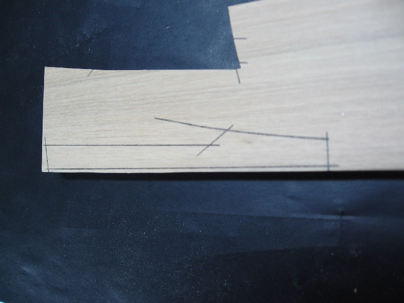
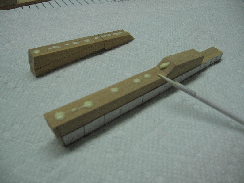
MAY 8 2016 (Mother's Day) Worked on the aft deadwood today and it took a number of tries resulting in numerous pieces added to the scrap bin. As always, after cutting and sanding I checked the fit on my light table (light box). I found myself chasing my tail a few times where I ended up creating the scrap. Eventually I ran out of patterns and had my master from which I traced the pattern onto a piece of translucent graph paper and then transferred the pattern onto the piece of boxwood. I used a 6H (hard) pencil to get a nice crisp sharp line. Eventually the pieces fit well enough and were glued together. I put a few dabs of wood glue onto both pieces, spread it with a small plastic tool I have for the job and then assemble the pieces. This takes a minute or two so the glue is getting tacky by then. The two pieces get rubbed together in a rotation to spread the glue between them further, working any excess out the sides and then they are aligned properly and held finger tight until it begins to set. This usually takes about another 3 minutes. I ended up with a section of the aft Deadwood done. The Rising Wood section between the main Keel and this assembly is not done, and the Knee piece is not glued on as yet as the top portion of it needs some shaping and fitting. I have purposely not cut the aft vertical end yet. After I have the Knee and Rising Wood added I will sand the back facing the stern post to the proper angle and add them all to the keel permanently. But I will need to clean them up and mark the framing heel step notches to both sides first. I find it difficult to not jump ahead and think about the assembly of other parts. There is so much left to do here at this stage. I should be concentrating on this stage and what comes next. Seeing as how I've learnt to slow down and do one piece at a time, I am sure the focusing of my concentration will also come in time.


-
I use rubber cement and remove it with an eraser. At first I applied it incorrectly but was soon schooled in the proper use by Druxey. 1. Apply to both the wood and template sparingly. Or two pieces of wood (if one will be opposite hand) and one template much later. 2. Let dry until tacky 3. then apply the template to the wood and press them together (or wood to wood if there are two pieces then repeat for the template) 4. let dry completely 5. cut just outside the line 6. clean up to the line (checking mating fits regularly) 7. when satisfied separate the pieces and clean up
-
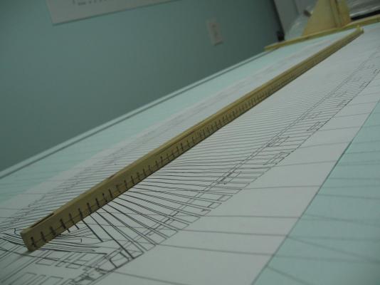
Ed from my hands on experience with sweeps... the length is required to reach the water without the oarsman sitting on a highchair Alan
- 641 replies
-
- 4
-
-
- greenwich hospital
- barge
- (and 1 more)
-
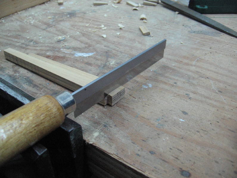
I was told to cut about 1/16" outside the line and sand/file down to the line. This has worked for me.... with a finer blade on a jigsaw. Possible you can use it with a finer blade on your saw.
-
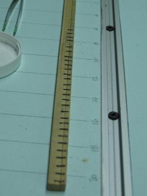
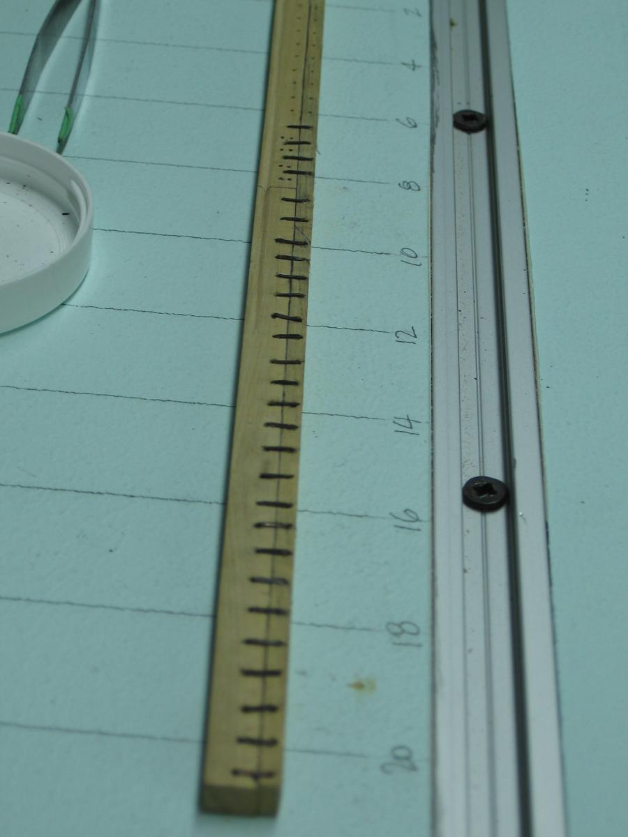
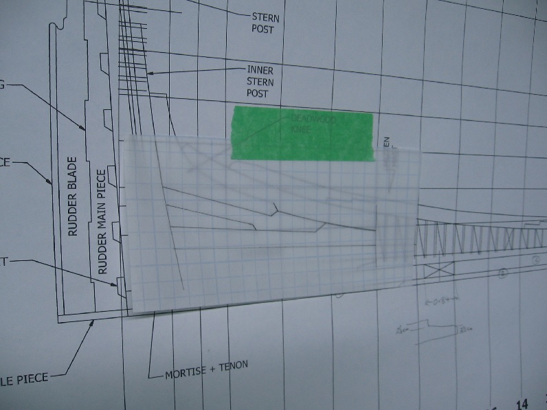
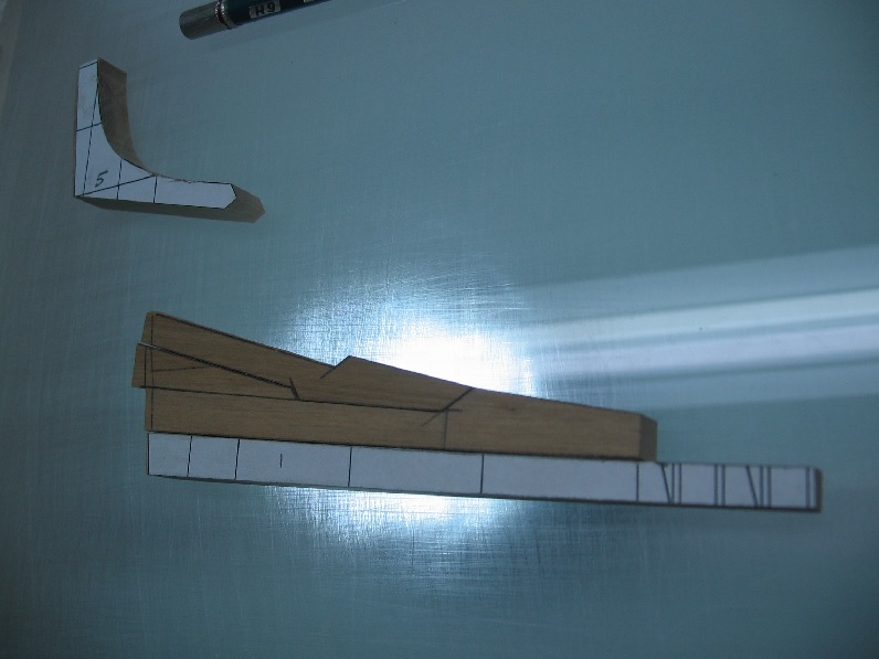
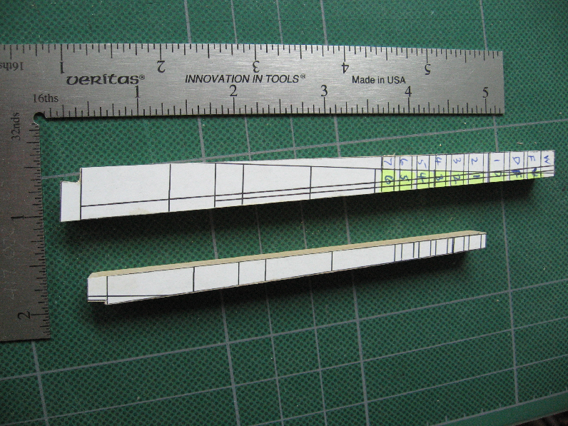
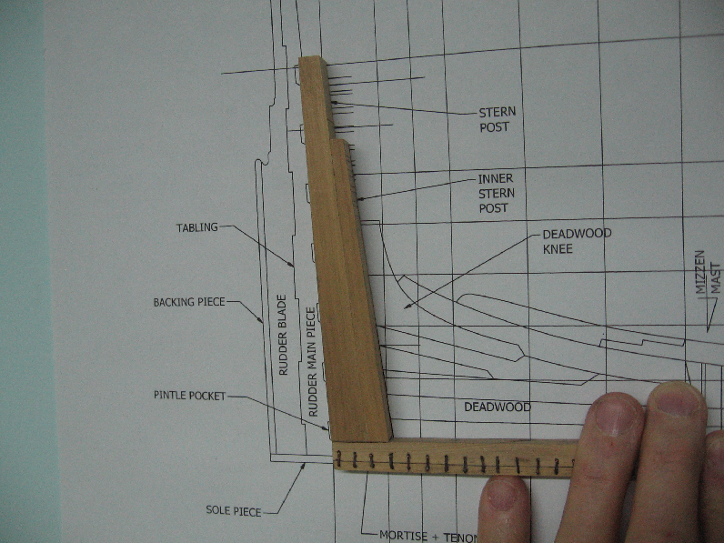
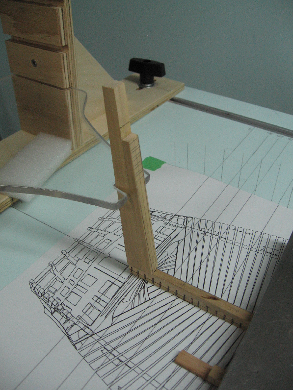
Sunday 01 May 2016 Made the Main Stern Post and Inner Stern Post today. Cut out the two patterns. Cut a strip of Castello Boxwood to 1/2" thick, Milled to 0.365" (23.36" at 1:64) Per the build contract the stem post is 23" square at the head and begins to taper from the underside of the deck transom to be 12-1/2" at the main keel. You can see I incorrectly identified the deck transom, highlighted them all in yellow and re-identified them correctly. Applied rubber cement to the wood and then to the back side of the templates. Let it dry to "tacky" and then applied the template to the wood. pressed them down and let them dry. Cut out the two pieces on the scroll saw about 1/16" outside of the line then sand down flush to the line on the table top disc sander portion of my combination belt/disc sander. I double checked the table was square to the disc first! Glued the two pieces together with yellow wood glue, pressed together and let it dry. Marked off the transom positions from the templates to the end faces. Marked of the centre lines on the end faces Marked off the taper on the end faces Marked off the rabbet line at the head and foot Marked off the tenon, cut and filed down to a snug dry fit into the main keel mortise. There should be multiple tenons but I simplified it to be a single tenon into the single mortise made earlier in the keel. Peeled off the templates Checked it to the plan.... perfect angle. Still needs to be tapered and recessed steps cut for the Transoms, but I think I will do the Deadwood first as it tapers with the stern post assembly plus it needs to be cut for the rabbet. The contract also calls for a "a square plate of iron of the knee kind" meaning a L shape, 5/8" thick x 4-3/4" wide with the vertical leg 3'-6" (and 3 x 7/8 bolts) and the horizontal 5'-6" long (with 4 x 7/8" bolts). I find it odd that they call up an iron plate below the waterline... Unless it is the newer mixed alloy... this makes sense. Then again it is recessed into the wood so it would be coated with tar before the copper sheathing was applied. Would anyone know for sure? That is enough for today. Thank you for following.
-
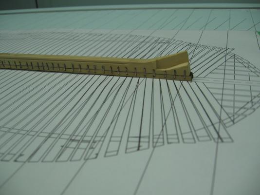
I still cannot take my eyes of the blades! Very realistic curvature If I didn't know they were tiny scaled down models I'd think these sweeps were the real thing. (I can smell the salt water and I'm 1000 miles from it)
- 641 replies
-
- 6
-
-
- greenwich hospital
- barge
- (and 1 more)
-
Bob, It was a different time for the Irish. At one time there were many restrictions to their lives that made survival an unbelievable hardship. From outlawing the language, family (sur)names, changing given names, restricting ownership of property, restrictions on participation in government.... they couldn't even own a horse. They came to America to find the Irish were not welcome here. There were signs in the windows - No Irish Allowed. Boys who signed on as fishermen in Ireland were left behind in Newfoundland to fend for themselves over the harsh winter so there would be more room for the cargo. (I think that may be how my family arrived). And we speak of the good old days! Alan Uà Niàll
- 649 replies
-
- 7
-
-
- dunbrody
- famine ship
- (and 2 more)
-
still seems odd to me as the one fellow mentioned how much swing (or pivot) do they allow imagining a seated fellow leaning way forward and way backward for the full stroke. If your crutch (or thole) allows the motion then... what the hey
- 641 replies
-
- 2
-
-
- greenwich hospital
- barge
- (and 1 more)
-
I have one bad eye and one worsening eye. What helped was 4 summers at HMCS Quadra (2 of which were spent working in the boat shed), over 40 years ago, sailing 27 foot whalers and 32 foot cutters. Spent 5 days in an open cutter on my Practical Leadership course. When pulling, the whalers were single banked and the cutters double banked. Each had different shaped sweeps due to the length inboard of the crutch. I was looking at Druxey's perfect sweeps with those curved blades and that is when the light went on and I asked about it. Of course I've no experience with any other era least of all barges... but I once built a raft when I was about 8! If it hadn't been for those memorable Sea Cadet summer camps I'd not have noticed.
- 641 replies
-
- 6
-
-
- greenwich hospital
- barge
- (and 1 more)
-
If we are indeed voting... Sweeps tossed Book sold... as you knew it would be!
- 641 replies
-
- 3
-
-
- greenwich hospital
- barge
- (and 1 more)
-
Yes Mike, it is as Druxey stated. The false keel was nailed on from the underside (not bolted through) and stapled from the sides. If she ran aground the false keel would peel off and hopefully create some clearance so she could float away. The copper cladding on the hull terminated between the false keel and keel. The false keel was sheathed separately so that if it peeled away the hull sheathing would not be damaged. If I were sheathing the complete ship I would have made a major faux pas as (I believe for this to work properly) the sheathing would be under the staples. As mentioned earlier, I intend to do a reverse break away and install a patch of copper sheathing with the layer of tar exposed outside of and under it. You are also correct when you mentioned it seems to have not been done before. I've not seen it either as yet! It could be that it is 240 staples! BUT I think it is because it does distract you from the beautiful crisp clean lines that are what you normally see when they are omitted. If I could expertly include to scale wood working tool marks on the keel and false keel I would but I am not that good. I have taken some effort to not make the assembly too perfect looking. I know that sounds like a bold face bucket of blarney (and my name is O'Neill) but if you look closely you'll see some effort in the less than perfect false keel to keel. My first keel assembly (some time back) was very clean.... but I've decide to try something different. Pray I don't make an assembled piece of drift wood.
-
Sunday 24 Apr 2016 Lesson learnt; opportunity seized. All staples installed. All staple blackening flaked. Likely due to being too long in the solution and possibly too strong a solution. The LOS blackening process is an oxidation layer on the surface of the material. If the layer gets too thick it can flake or peel/pop off in handling. I figured I would simply install them now and re-blacken them in place later... but when cleaning them up the strangest thing happened. They were left with a hint of patina suggesting ageing... and I like it. All of a sudden the copper stands out against the wood and it looks like the real staples I posted earlier Let us wait and see if the feeling sticks with me. Next I tackle the stern post(s). Installing staples - prior to cleaning up. After cleaning up