HOLIDAY DONATION DRIVE - SUPPORT MSW - DO YOUR PART TO KEEP THIS GREAT FORUM GOING! (89 donations so far out of 49,000 members - C'mon guys!)
×


AON
-
Posts
2,866 -
Joined
-
Last visited
Content Type
Profiles
Forums
Gallery
Events
Everything posted by AON
-

De Zeven Provinciën 1665 by Dražen - Scale 1:45
AON replied to Drazen's topic in - Build logs for subjects built 1501 - 1750
it is obvious I am going to need more elastic bands!!!- 487 replies
-
- 4
-

-
- ship of the line
- 80 guns
- (and 1 more)
-
welcome to the group!
-
Yikes. I had that happen to me and the timing was disastereous. Hope your timing does not fair badly.
-
It will hopefully be a permanent correction but one never knows for certain.
-
Thank you Druxey and Albert for the kind words and everyone else for following along.
-
Funnily enough as I approach retirement I find I reminise the simpler times when I started my career at a drafting table and tee square with my pencils, sanding pad, eraser, compass, triangular scales and french curves. It was a less stressful time and took real talent to create the perfect engineering drawing. With CAD anyone can draw a straight line. It annoys me to no end that they insist on making them 20 short straight lines instead of one single long continuous line. Kids these days....
- 3,618 replies
-
- 8
-
-
- young america
- clipper
- (and 1 more)
-
get started??? what are you waiting for?
-
Saturday 28 JAN 2017 It has been I while since I posted any progress... it goes rather slowly. I've been putting more hours into a paper for work than into my model... plus I am getting injections in my left eye to correct a condition with my vision. It has affected modelling and my day job. I spend hours reading engineering drawings and documents. I have branch retinal vein occlussion caused by macular edema. I have a fluid build up (bump) at the back of my eye very near the focal point that causes lines and print to pull together. I occasionally still see a fine black dot due to my last (first) injection. Two more to go and hopefully the fluid pocket is gone and things reshape back to near normal or better yet.. normal. Modelling isn't a race but it does keep calling me downstairs.
-
elegant, clean and delivers (works as expected) very nice addition to your working/living space
- 968 replies
-
- 5
-
-
- hahn
- oliver cromwell
- (and 1 more)
-
I had to Google Long-Sault and see you are out by Cornwall. I've dealt with Exotic Woods in Burlington (by Hamilton) but not mail order nor cut/milled to size. Give them a phone call and discuss what you need. I found the website helpful and them very helpful over the telephone... but I drove over (45 mins) and picked up what I needed.
-
Looks like you'll be getting some awesome practise in with you're milling machine! I understand the front framed plexiglass panel being held by magnets so it can be removed easily. I suspect the plexiglass will keep the wood frame from warping. Possibly a thin felt gasket glued on the inside edge to keep the dust out? I confess I like your design. You could employ a more traditional floating base... a open backed box that slips over the strong support that is bolted to the wall. That way if someone looks underneath they see a finished face. A set of strong magnets (or screws) could secure the "box" to the "support".
- 968 replies
-
- 4
-
-
- hahn
- oliver cromwell
- (and 1 more)
-
Mike Too bad you are half a world away as I'd offer up time with my tools in my play room. I completely understand and appreciate the feeling of discovering the beauty hidden inside ordinary wood.
- 968 replies
-
- 7
-
-
- hahn
- oliver cromwell
- (and 1 more)
-
I can attest to the fact that even after 41 years... even when I'm right I am wrong. what is her's is her's and what is mine is her's. only one opinion really matters. she's a damned good cook. she can balance the books. she knows how to save a buck. I'd be lost without her. She doesn't know how to build a model ship (and she's convinced I'm faking it)
-
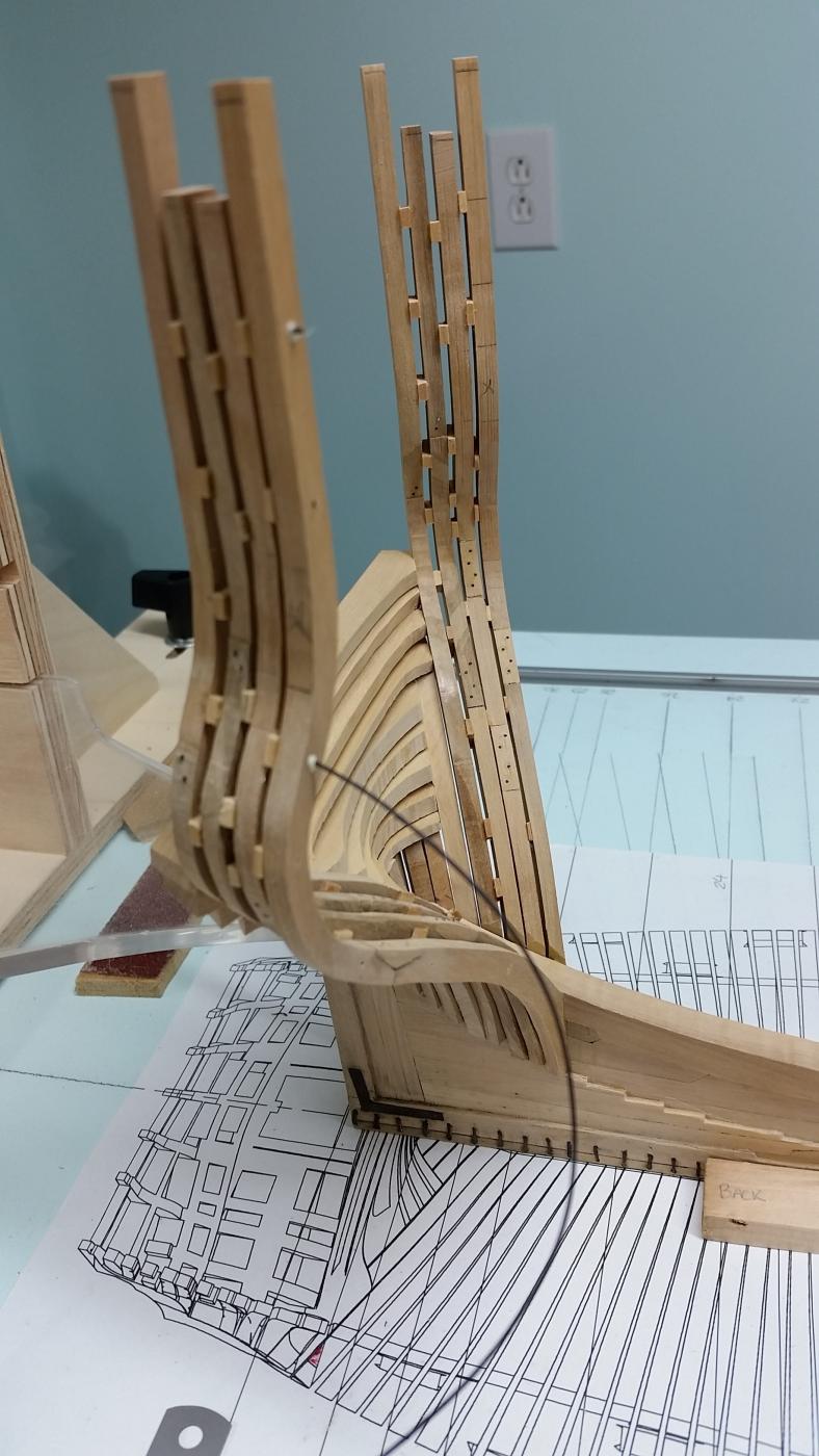
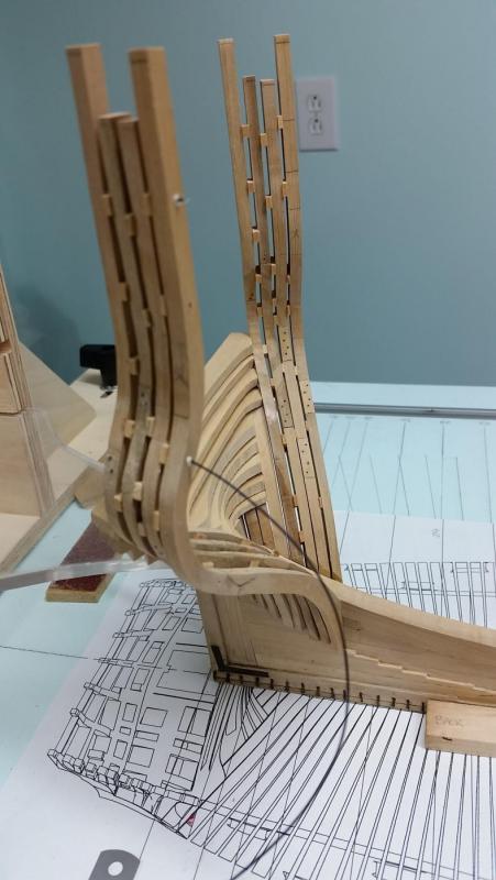
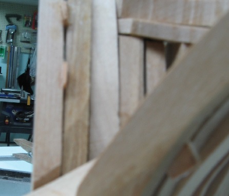
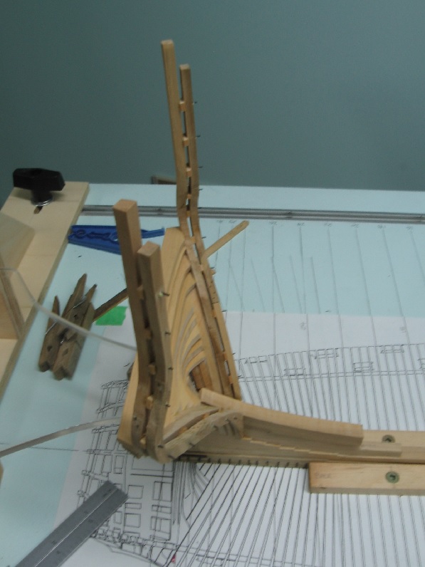
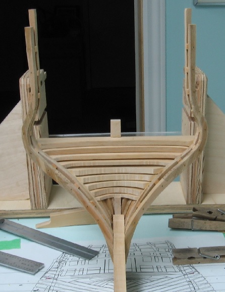
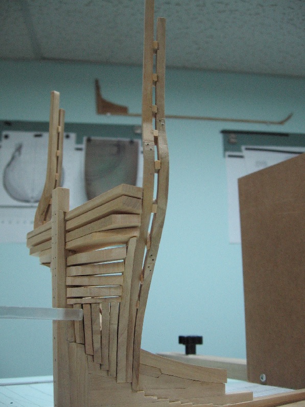
Sunday 13 Nov 2016 I managed to sand and install the last two chocks. My first attempt at sanding ended in the part disappearing under the stop (because it was so thin at 0.02" or 0.46mm) and being sucked up by the vacuum. The chocks are hemlock and measure 10" in height (approx 5/32"). They are 9" on the plan but at this build scale who can tell the difference. Drilled and installed the bolts into the frame and through the chocks then trimmed flush. Cut and milled a blank of Costello 0.079" thick for the next frame set. Cut that length in half and rubber glued them together, clamped and ready to trace the template and cut the frame pieces in matching pairs.
-
All: Thank you for he likes. It is very encouraging. I was telling my darling wife about the missing last chock and even she asked: "will anyone see it?".... I could only respond that I see it now. Carl: so do I! It is because they are cant frames. Once I get out of this area (and those at the bow) I should be "smoother sailing".
-
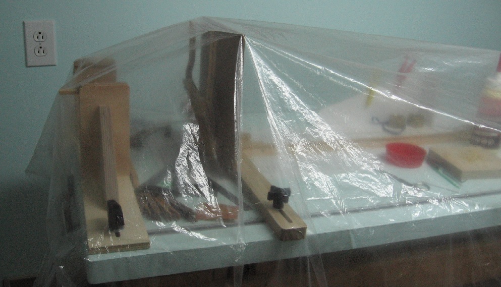
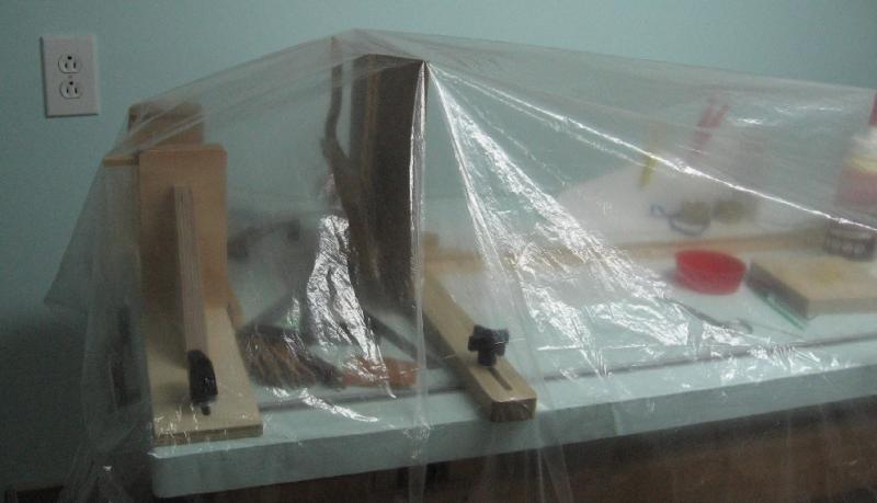
Saturday 12 Nov 2016 Been away from it too long but feeling up to it again. Today I fitted the chocks between the frames. Presently the glue is drying and setting. Tomorrow I will drill and install the bolts and start on the next set of frames. I chose to install the top most chock first to set the space properly. Subsequent (lower) installations were a bit of a challenge as the more I installed the less I could pry the frame open to receive the chock. Each was sanded down to fit snugly. I filed vertical grooves (pockets) into the chocks to hold the glue because most would be scraped away as the chock was slid into place. The lowest ones were the worst as they were very thin. I wanted to installed one more lower as they should be in groups of three between joints but it was a bit too thin for me. I might try tomorrow when I'm fresh. Presently the whole table is covered to keep the dust off over night. I do this after every session.

-
I can find nothing of the detail your asking for. I have copies of standing rigging from here: http://www.modelexpo-online.com/images/docs/MS2260/MS2260-Syren-Instructions-Chapter-18.pdf but it is American (US Brig Syren 1803) and somethings don't agree with other books I have. You might like to review it just the same though. Sorry I was of no help... and late to boot.
-
did you say you had Rigging Period Model Ships by Lennarth Petersson, Chatham Publishing, London, 2000, ISBN 1 86176 061 2 ?
-
That certainly looks like a solution. I haven't had any luck finding it as yet amoungst my mess of data.... but I have learnt I need to organize it all better.
-
I may have something but it will take awhile to dig out as I am nowhere near this point in my build but have been collecting info for two years. If someone beats me to it you can bet I'll add their info to my "library".
-
Thank you Jason. I would have responded earlier but I threw my back out Friday morning and this is the first I could sit at the computer. It is aching a bit so I going to be gone a bit yet.
-
An actual miniature eye splice... I've dreamt of doing this but having made many a splice in real life lines of various sizes with fingers, feet, fig and spike I have a feeling it will remain in my dreams My copy of The Masting and Rigging of English Ships of War 1625-1860 by James Lee covers quite a bit of this. The diagrams are very helpful but when then don't exist the verbage needs re-reading multiple times before I can start to make some sense of it. If you need anything from it in particular just ask and I'll be there for you. I'll look at the section for the bowsprit rigging tonight and then PM info to you. Yes, if you are offering a copy of the photos I am gathering everything I can to help me with my build. Time for me to get off to work.