AON
-
Posts
2,871 -
Joined
-
Last visited
Content Type
Profiles
Forums
Gallery
Events
Everything posted by AON
-
 Looking forward to watching your progress
 -
We remain our own worst critics. If I had your talent I could throw mine in my scrap wood pile
- 504 replies
-
- 5
-

-
- washington
- galley
- (and 1 more)
-
Mark, I stumbled on the information while trying to figure out what was in his left hand. Then, while transcribing hundreds of old newspaper reports on the comings, goings and actions of the Bellerophon I stumbled upon the report of the loss of her figurehead.
-
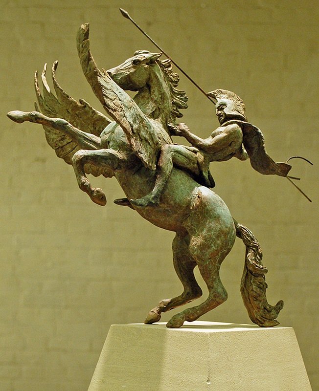
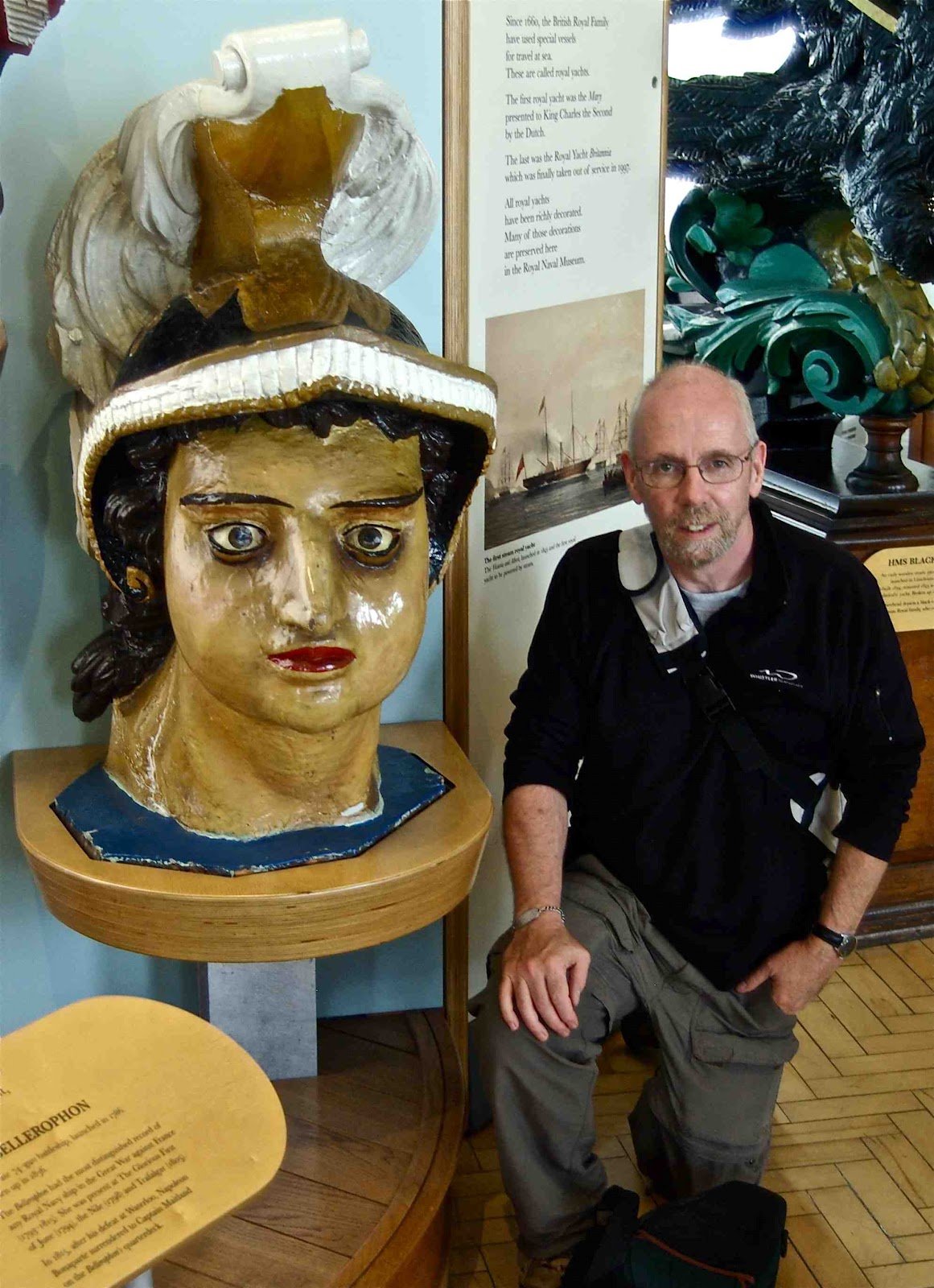
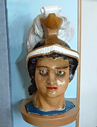
Good morning all and thank you for the likes. Mark: those figurehead images you are looking at are the second figurehead made for the first ship. The first figurehead is described as: Before it was damaged the figurehead represented Bellerophon as a nude figure draped in a red cloak riding Pegasus, his right arm raised, holding a javelin. The horse’s wings were spread. (source: http://figureheads.ukmcs.org.uk/?p=1715 ) On 14 July 1793, southwest of Scilly Isles HMS Bellerophon collided with HMS Majestic in gale force winds where she lost her bowsprit, foremast, main top mast, figurehead and cutwater was smashed. The figure head was replaced with something a bit simpler as the Royal Navy was issuing orders to try and control the expense on ornamental carvings on the ships of the time. All that remains of the second figurehead of the first ship named Bellerophon, is the head seen in many photos, which was all that could be salvaged due to rot. Alan
-
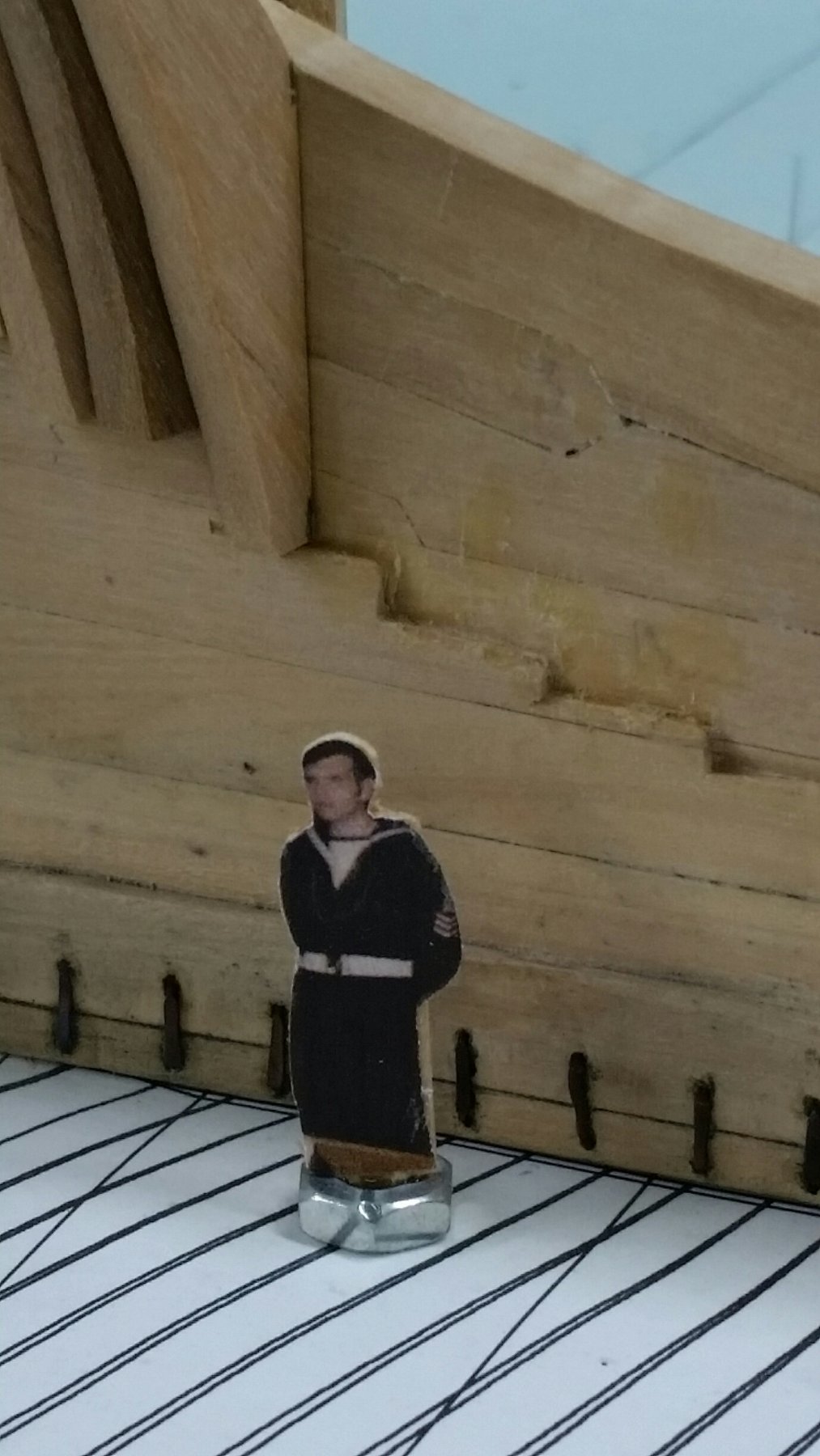
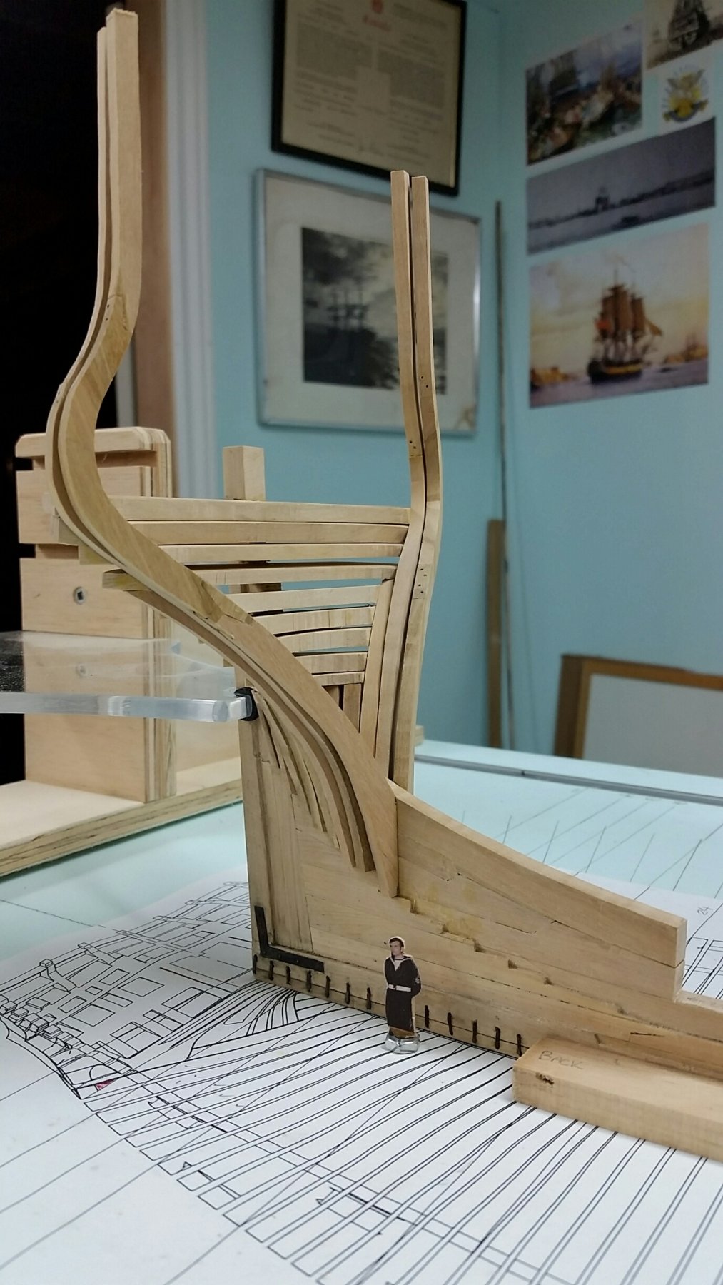
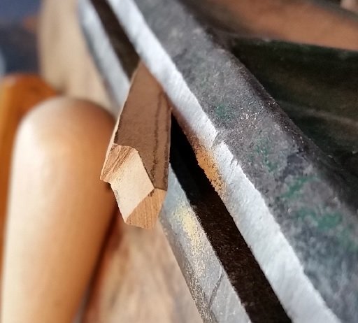
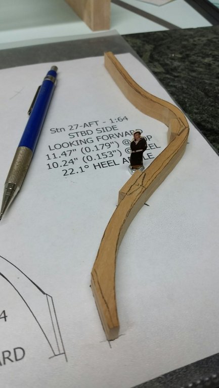
Well, here we are in December and I'd like to say I'm caught up to where I was but it ain't so. I practised a bit with bevelling my chock joints in the cant frames and found a method that seems to work for me. First I sand the chock bevel with the table disc sander, table angled to get it set proper. Then my I mark off the depth on the futtocks. (I tried using my scroll saw with the table tilted but it only works on one side and not the other) I cut an angled relief to the line and then using a sanding stick file it down... bevelled, to near the line. Check the angle with the chock, all placed on the marble slab I stole from the kitchen to keep it flat. Then I finish with a file and sharpen the corner with a chisel. The figure (sailor) is my Grandfather. I have two frames together and made pieces for eight more. I hope to get caught up over the Christmas holiday. Looking ahead.... I've also been researching the original figurehead, for which there seems to be only a description but know sketches. Bellerophon on Pegasus with his spear. I've signed up for a bird carving course at Lee Valley Tools in Niagara Falls, Ontario, in February, to help me try to carve my figurehead in the years to come. I also purchased Bill Short's rotary carve techniques PDF Booklet "The New Carving Ornamentation for Ship Models" found on the forum home page bottom right hand side. Seems I have reading to do also. Might attempt rotary carving the other figures. But again that is years from now so I have time to become an expert... or possibly just good enough.
-
re: 1/2" dowels, slots and screws. I hadn't noticed the details. Had to zoom in and there it is, nice holding/clamping jig!
- 3,618 replies
-
- 2
-
-
- young america
- clipper
- (and 1 more)
-
There was a news article about a painting discovered of Nelson that hadn't been touched up. He didn't have an eye patch but was blinded in one eye and had a wicked scar above his eyebrow. Regarding tiny sailors on the model. I've been thinking about one at the head on the seat of ease to help explain what those boxes are (seriously).
-
I thought I was reading poetry for a moment.
-
These are the tips I snip and paste into my reference library. When I ever get to this stage I'd never remember them! Thank you.
-
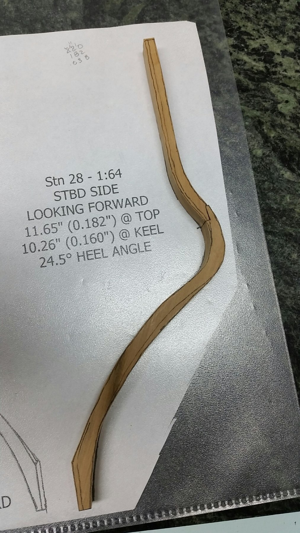
This is where the 3D programs come in handy for templates of sheet metal work. If the outside of the hull were given a thickness (or thin-ness!) the program would create a flat view of true length as a pattern. Having said that, and knowing the build versus the plan are three different things, I'd like to think that I'd measure off the build and plot it as you're doing. Rough blanks and trim to fit. In the old pencil draughting days we'd calculate the distances and then create (plot) the flat (pattern) view. Alan
-
Tried to send you a PM to check if I am on your workshop notice distribution list but the system tells me you cannot receive any more messages.
-
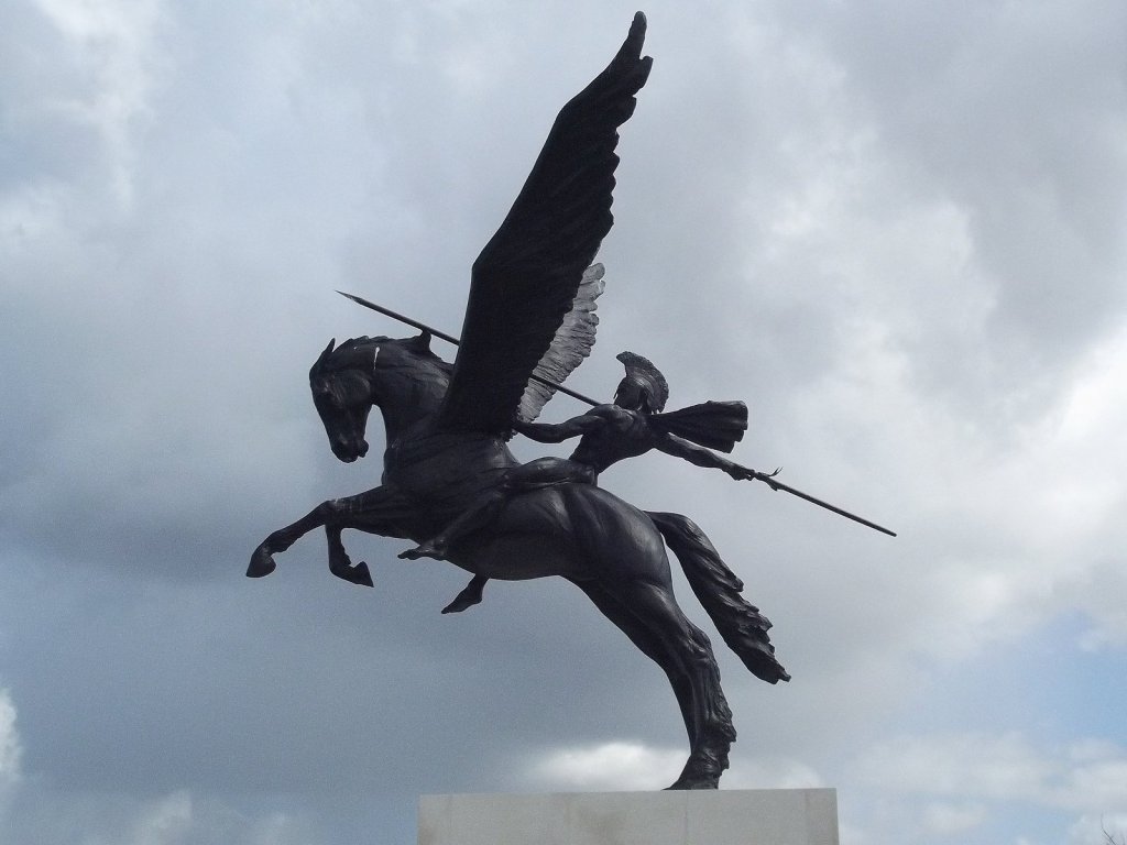
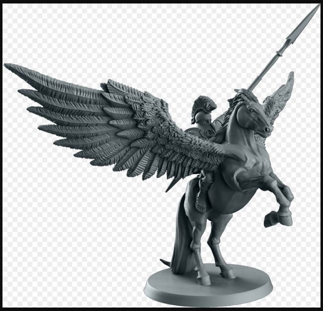
This is what I've seen as sculptures/statues/stamp that might represent what it looked like. You can understand why I feel it was crowded around all the standing and running rigging at the bow.


- 28 replies
-
- 6
-
-
- bellerophon
- 74 gun
- (and 1 more)
-
Good evening Tony, I have been researching the figurehead of the first Bellerophon as launched. All I can find is the following: source - http://figureheads.ukmcs.org.uk/?p=1715 "Before it was damaged the figurehead represented Bellerophon as a nude figure draped in a red cloak riding Pegasus, his right arm raised, holding a javelin. The horse’s wings were spread. All that remains is the helmeted head. The figurehead would have been painted white during its time in service. In 1814 the Navy Board approved more use of gilding and colours for figurehead decoration." The accident was on the 18th of July 1793, SW of the Scilly Isles where she collided with HMS Majestic in gale winds. Have you seen anything while you were researching. I see you have the representation of (I believe) the replacement figurehead. With all the rigging it is a busy area to have a full figure with a spear, horse and wings! bellerophon figurehead original state library victori australia image H99.220(slash)1026.tif

- 28 replies
-
- 1
-
-
- bellerophon
- 74 gun
- (and 1 more)
-
Good morning Bob, I have just spent two days going through your build log yet one more time. Thank you very much for all the pics, build comments, details. I will be referring to your build over and over (along with my library) and over as I progress on my ship. I haven't gotten very far as work has its demands so I crawl along... but I retire in one year and will then have tons of time. You've done a fantastic job and you are sooooo close to done. Alan
-
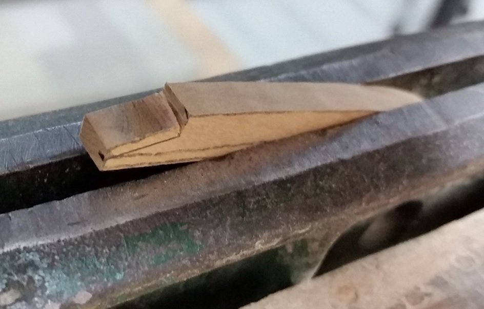
The angle seems a tad acute but I should only blend to touch that outer corner of the frame.... in theory.
-
I am back. Having successfully bevelled a futtock chock joint. What a painful process it was for me to accomplish. I pray I've got it going the proper way. If not S/Lt Martin (she has since been promoted to Admiral) will have my hide! Feels like I've a quadrillion to go... so many opportunities to improve
-
I PM'd you some info. look at page 35 Wing Transom Knees: WING TRANSOM KNEES(130) ---- To have two wing tranfom (transom) knees fided (sided) 12 inches, the fore and aft to be 16 feet 0 inches long; the athwartfhips (athwarthships) to be 6 feet 0 inches long, to fcarph (scarph) with hook and butt(78, 81, 104) upon the upper strake of spirkitting(131) and bolted with 5 bolts 1-1/4 inches diameter in the thwartfhips (thwartships) arm, and with 8 bolts in the fore and aft arm, and with 2 bolts of 7/8 of an inch in the lip of the scarph.
-
I have both the Elephant and Bellerophon contracts. Arrogant class following the Bellona. I will look at them in the morning and get back to you.
-
If only I had a mill and an angle plate. I should be able to "get 'er done" with one of the toys I do have... but I may never get joints quite as tight as yours.
-
Thanks for the encouraging words Druxey. See you Sunday.
-
I noticed there is a problem. I was staring at it but couldn't see the forest (it) for the trees (frames?). After studying TFFM Vol 1 and 3 this weekend it became obvious. I hadn't been chamfering my chocks/joints in the cant frames to account for the angle and sanding. Too much of the chock was exposed and would be sanded away when fairing the inside surfaces of the frames. In volume 1 of TFFM David simplifies the joints (square end butt joint) in the cant frames. In volume 3 of TFFM Greg simplifies the joint (half step simulating the chock but cut back to the proper chamfered depth) in the cant frames. So what I've put back on I have yet again taken off. I believe I'll get it this next (last?) time! "Seems there is always time to do it over".
-
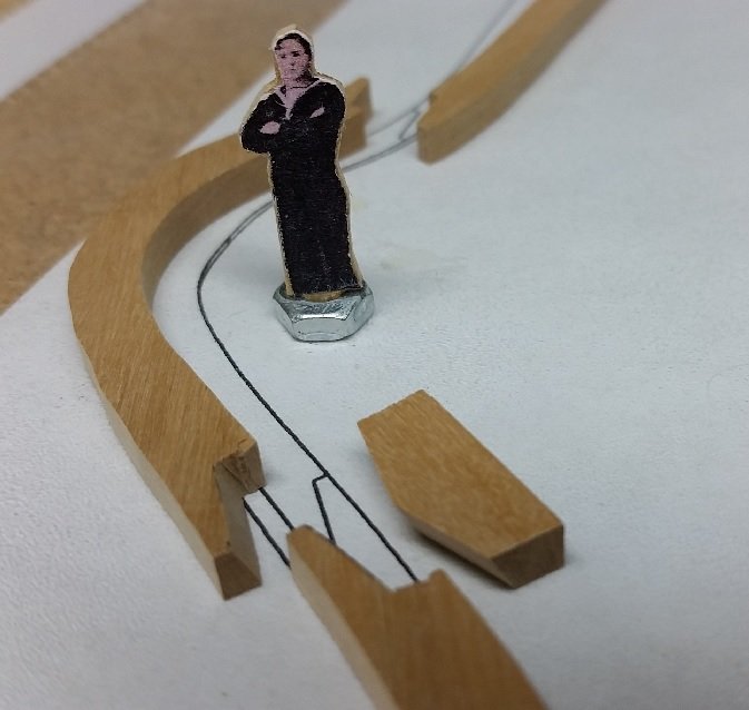
So let me introduce myself CPO and Bosun (Bos'n or Boatswain), 141 Royal Canadian Sea Cadet Corps Bellerophon of Welland, Ontario (1972). I shrunk my self to 5'-6" from my present 5'-10-1/2" (glued to a thin piece of wood and that glued to a tiny hex nut to keep me upright) I'll be adding my father (Able Seaman RCNVR 1939-1945) and my grandfather (Able Seaman NRNR 1914-1918) to the crew. If I find one of my wife (Navy League Wrenette Corps Patrician of Welland) in uniform she will be signed aboard also... women allowed. The only criteria for family to join is they must be in naval uniform. I won't likely post again until I get back to at least where I was before I tore frames off. take care till then.


-
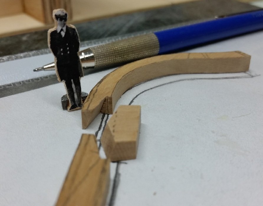
As of late I've been using a 0.5mm (0.02") mechanical pencil... it doesn't require sharpening just refilling. I should however erase the pencil tracing (transferring the pattern to the wood with carbon paper) on the paper pattern when I assemble the wood pieces over it.! As an aside, I have noticed some people inserting scale cut out cartoon people into their builds to effectively demonstrate the scale. I will be inserting a much younger me into my next build stage photo. So if you find yourself wondering... yes it is me, not some total stranger lurking about my ship.
-
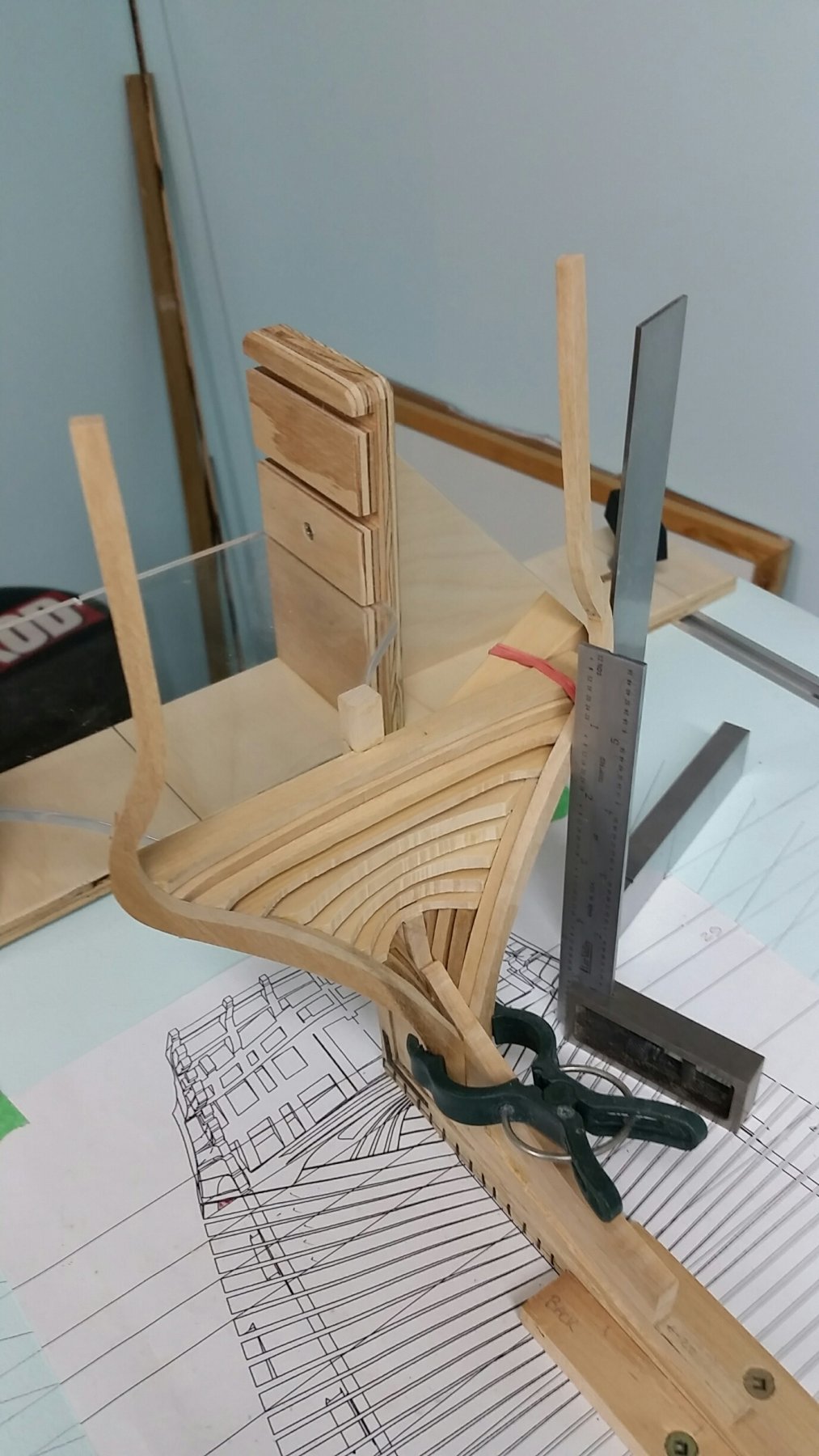
Thank you for the message. You should be aware that I haven't any great skill level and I appreciate I've jumped into the deep end of this pool but find this forum to be my life jacket. Making some progress. I find the wood glue does not adhere to the plastic sheet (picture below). It did to the glass, so this is quite a bonus! I have (as you'll see below, one set of full frames installed, I installed one half of the next set this morning and hope to get the other half up tonight. I've cut out the next set and need to fine tune the chocks before I glue the pieces together.