HOLIDAY DONATION DRIVE - SUPPORT MSW - DO YOUR PART TO KEEP THIS GREAT FORUM GOING! (Only 72 donations so far out of 49,000 members - Can we at least get 100? C'mon guys!)
×


AON
-
Posts
2,861 -
Joined
-
Last visited
Content Type
Profiles
Forums
Gallery
Events
Everything posted by AON
-
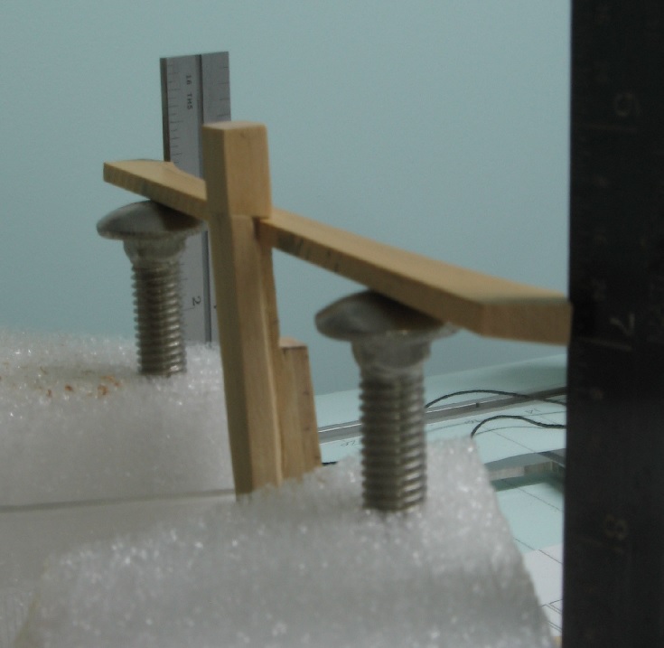
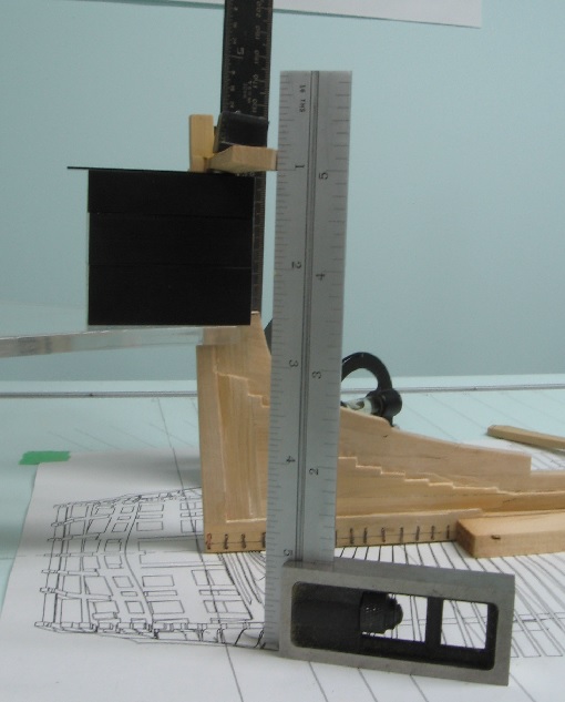
 Devised a possible new easier method to set up the transom pieces. I used a couple pieces of packing Styrofoam saved from some purchases (yes I am a pack rat) Drilled a 0.3125 hole in for a 0.3665 OD carriage bolt The snug fit allows me to move the bolt up and down while the Styrofoam holds it snugly. I use my scaled squares to level it off. I also installed some bolts but need to research a bunch more.
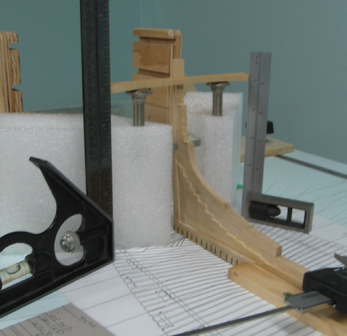
-
Thank you for the comments Ed and I welcome all suggestions so don't hold back. My table was levelled breadth ways with the lift mechanism and applying personal weight to one side so the bubble is close but you are correct, the smartest way is via measurement. I used my vernier depth gauge to setup and watch the bubble to assure it didn't shift. I originally tried setting up with a measured tick mark on cardboard but the vernier was less forgiving. As this top most transom piece (wing transom) sets at an angle I cannot put my shims under as I would like to but rather only the tip or edge makes contact. This is very time consuming and tipsy. I have been looking at David's fixture in TFFM volume 1 page 67 and may end up doing something more like it.... as Greg says in Vol 3 page 14: he has decades of ship modelling experience. I also bought some pins and will be employing them as I've seen done by another skilled fellow here on the forum! My 30 gauge copper sheets came in today. So I've quite a to do list to work on.
-
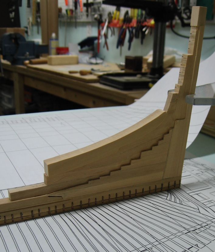
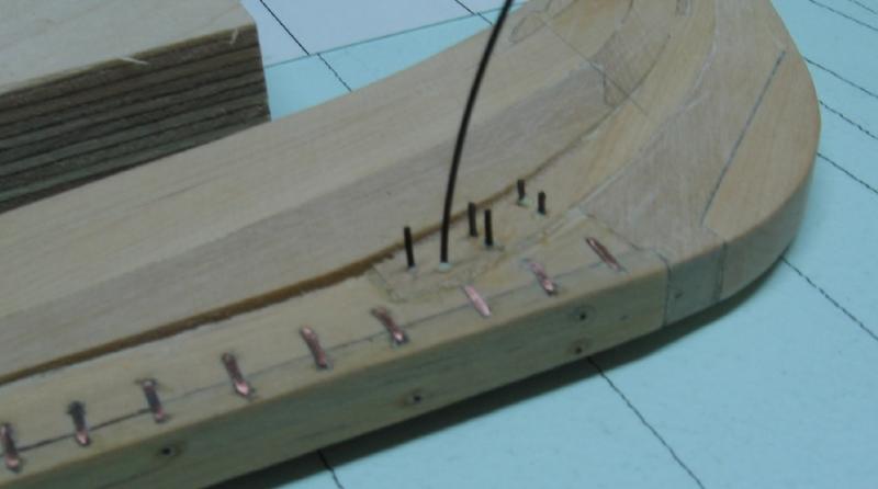
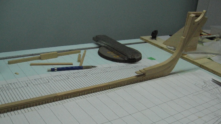
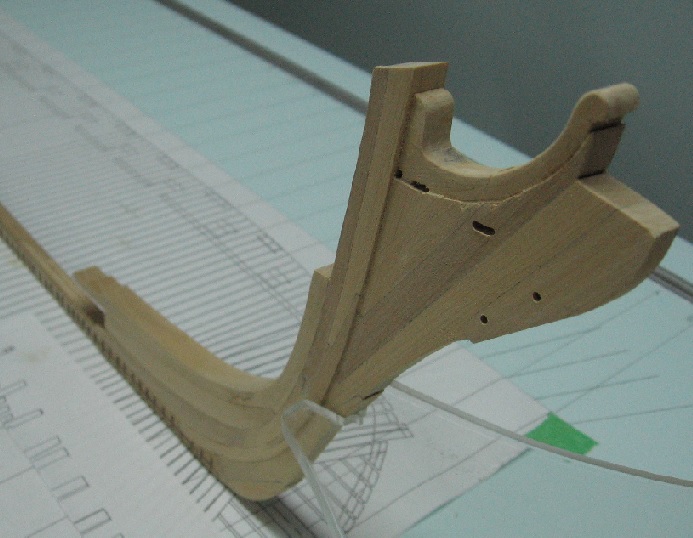
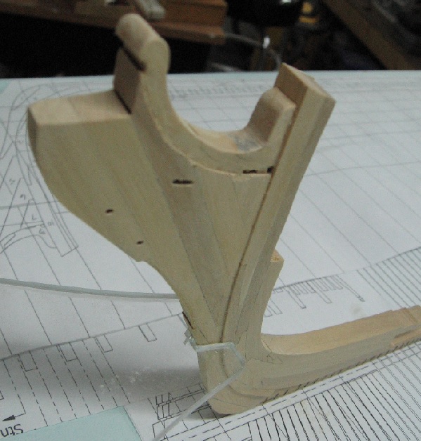
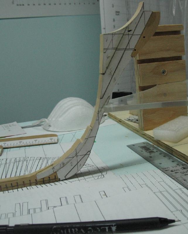
Sept 05 2016 Completed sanding, relief cutting the stem and stern... and dry fitting the wing transom (to figure out how I might do it). I need to add bolts to the stem post assembly and then add the horseshoe at the bow and the L (angle) bracket (knee plate) at the stern. Attempted to make these from wire (flattening and filing) but this didn't work very well for me. I've ordered some gauge plate to use instead and expect it to arrive this week.... so the transom pieces should go up permanently next weekend.

-
Sept 03 2016 Installed the last two pieces of the Rising Wood. Dry fitted into place (a tight fit) glued and clamped Done I have to chisel in a few more reliefs in the aft deadwood and likely sand a bit more on the stem assembly before I fit the transom pieces that are already cut out as I won't be able to lay the assembly down on its side to do this work if the transom pieces are installed
-
I had to phone in my order as the website connection timed out.... but it is on its way
- 641 replies
-
- 2
-

-
- greenwich hospital
- barge
- (and 1 more)
-
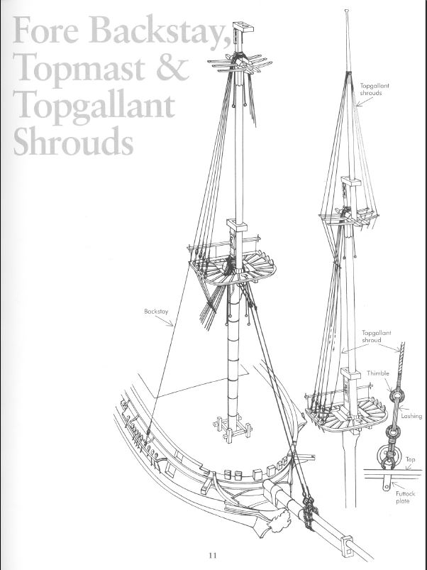
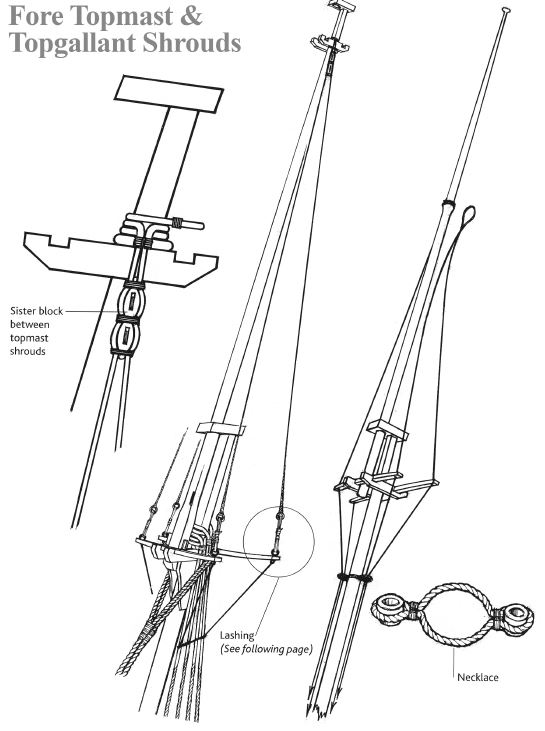
image is the one mentioned above from: Rigging Period Fore-and-aft Craft by Lennarth Petersson, Chatham Publishing, London, 2007 pg 81 American schooners
-
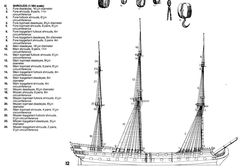
FYI - Anatomy of the 74 Gun Ship Bellona by Conway , page 96, plate 12, agrees with the rope sizes for the Victory. See attached image The only other reference I can find for the Topgallant Shroud connection to the mast is for American Schooners date early 1800's and they are similar to the Topmast Shrouds. There is a step in the diameter of the mast creating a shelf that acts as the stopper so they do not slide down. I wonder if all ships with this rigging were similar?
-
Thank's Druxey but what's the fun in taking the easy road? Think of everything I learnt taking the not so worn path. (... though had you been at my side I would have learnt as much without so much pain)
-
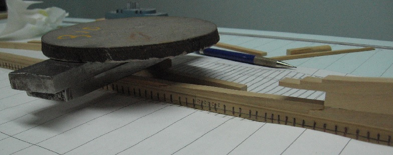
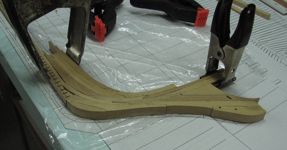
AUG 20 2016 Sanded down a piece of eastern hemlock. It is thicker and wider than required. Soaked it in alcohol for a minute. Fit into place with some minor trim to the length and then clamped in place with elastic bands. Letting it set now before I secure it and sand to fit. thickness and width. This was harder than it seems as it took four attempts. One broke. One was trimmed too short. One was clamped with real clamps and they damaged the surface.

-
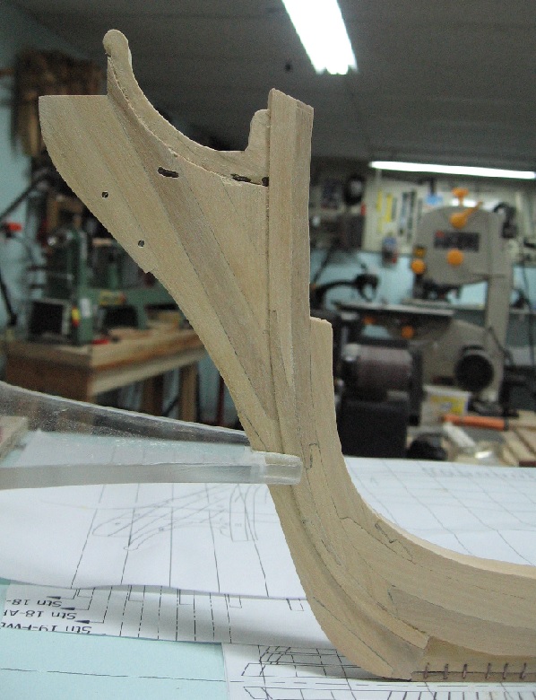
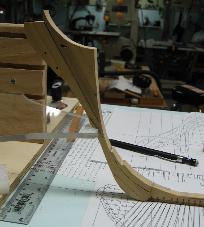
19 AUG 2016 Completed the shaping of the stem assembly. Chiselled in along the lower/middle/upper stem post to get the relief depth then sanded to shape. Then did the same to the knee of the head and extension as it is narrower yet again. Did a little damage on the edge of the filler pieces with the last step. A little cleanup to be done on her... a few passes with finer grade paper and a tack cloth. I have yet to add the cutwater strip to the stem assembly and the last pieces of the rising wood on top of the keel. Then I will start building at the stern, adding the transom pieces.
-
... and the pine tree paper air freshener cutouts dangling from a string overhead
- 649 replies
-
- 5
-
-
- dunbrody
- famine ship
- (and 2 more)
-
Thank you jbshan for the idea. As the stem assembly has yet to be sanded to thickness any edge bevelling would be lost. I wonder if I can scrape something in after the re-shaping is complete? Will consider it when I get that part done. Robin... It scares me too. Part of why I jumped into the deep end!
-
scarf joints
AON replied to dennistestagrossa's topic in Building, Framing, Planking and plating a ships hull and deck
I share your pain. Making any joint match almost flawlessly is a talent that seems to elude me. I find that I should cut out one half then fit it on top of the other half and mark the matching outline with a very fine pencil. I then cut (scroll saw and/or chisel), file and sand (in that order) to fit. Leave the "nose" end extended a bit. The pencil outline will be just outside where I need to be. If I can get that to match it allows me to bring (sand or chisel) the nose in a little bit for the final fit. I still cannot make them perfect and tight but the real build was not. It will take a lot more practice for me to "get it". Alan -
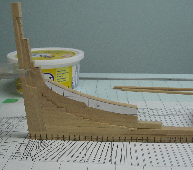
I added the remainder, Lower Apron, etc... and then the Knee of the Head and the Extension.


-
I used my light table for the dry fitting and had to suffer through holding it over head to the florescent light for the final fit, Some are quite brutal (for me) as I am not skilled enough as yet. Practise makes perfect... or makes one more frustrated. I have been collecting the sawdust so I hope to fix the worst of it up after shaping the thickness reveals more things that aren't visible presently... or I might be pleasantly surprised.
-
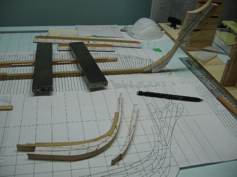
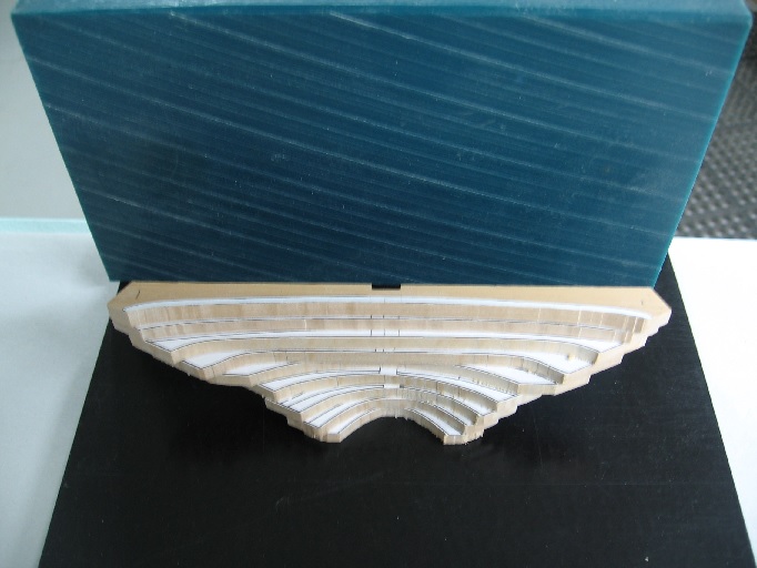
17 Aug 2016 Summer has kept me otherwise occupied and I haven't gotten much progress on my build in over a month... however on the plus side it hasn't rained much so the grass didn't grow and so did not require mowing! (But the flower gardens needed watering and my water bill was enormous). Earlier this month we went to see the live musical thriller Sweeney Todd at the Shaw in Niagara on the Lake ( http://www.shawfest.com/playbill/sweeney-todd/) ... not quite enough blood in the show but we enjoyed it non the less. Regarding my build. I must say sanding two curved pieces to mate near seamless is a art I've yet to master. I am much better now than I was a month ago but there still is much room for improvement. I suppose my frames will make or break me. I managed to get the aft most keelson piece (over the deadwood knee) sanded to match fairly well. Then I work, and re-worked and re-re-worked the stem assembly. In the end I had all pieces dry fitted to what I thought was acceptable. Then I started gluing to the keel and upwards.... re-re-re-sanding one more time to as imperfect as I could possibly manage. I don't necessarily want it to be seamless as the actual builds weren't but I do want it to be a little better than where I am. The problem is that until you've mastered it you end up chasing your tail and eventually screw up totally and find you've just made more scrap. Knowing when to say enough is enough is another talent I'm working on developing. Here is my progress to date.

-
I confess I was originally not a fan of the light coloured chocks... but as the ship grows I have changed my mind. I think the developing pattern has triggered my CDO switch ON
-
Thanks Don All I need now is some bad weather so I can lock myself downstairs with the ship and not feel like I am missing another beautiful day.
-
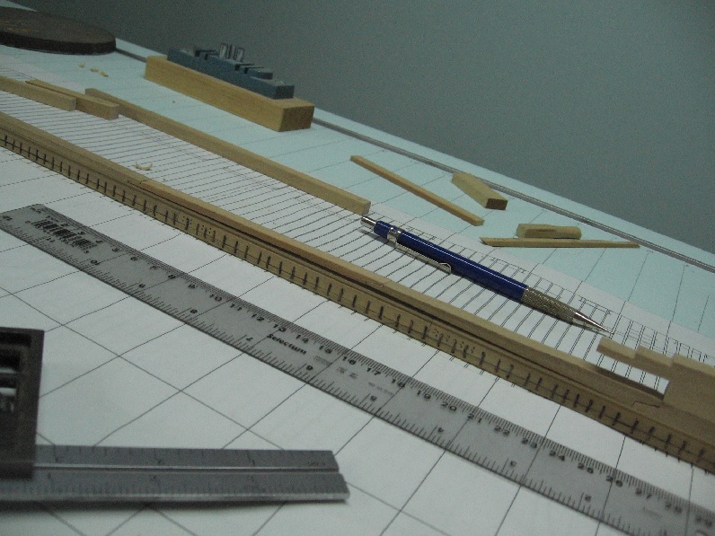
Although embarrassing it is human error, mine and the original draughtsman. I never thought to blame the measuring tape. I have to say your suggestion to make rulers to my build scale has been unbelievable worthwhile!
-
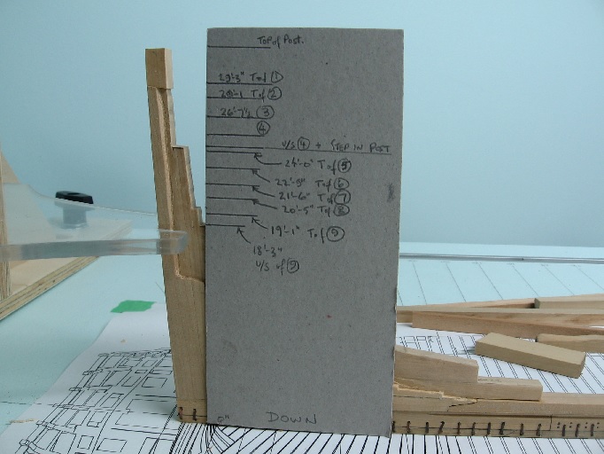
Sunday 02 July 2016 Some time has passed since my last posting here because I had revealed yet another issue. Druxey had commented that I should assure I get the wing transom set at the proper angle or everything would be thrown off. When setting the angle something seemed amiss. Upon studying the original sheer and timber plans from NMM it became obvious they did not agree with regards to the placement of the transom pieces. To add to this my stern post was short by almost two feet (my error). After considerable reflection I marked the proper heights on a piece of stiff cardboard. I cut off the top of my stern post to be flush with the upper side of the wing transom and then grafted an extension to my stern post to be the correct height. This has yet to be sanded. I then had to adjust the height "shelf" of my inner post and nipped off all those wonderful pocket extensions. I am concerned for the adjacent frame templates now as they may be out of alignment. I'll be double checking this before I make these aft frame timbers. I've rough cut all the transom pieces and will fit them after I have the stem post assembly made and attached. I'll be working on the stem post next.

-
I find owning a house and summer time provide all the necessary distractions to avoid boredum. The grass continues to grow and cries to be cut. The sun shines beckoning me outside. More importantly..... the fish are jumping! When I finally get downstairs to find myself emersed with the model for hours everything is fresh and new again.
- 191 replies
-
- 1
-
-
- victory
- caldercraft
- (and 1 more)