MORE HANDBOOKS ARE ON THEIR WAY! We will let you know when they get here.
×
All Activity
- Past hour
-
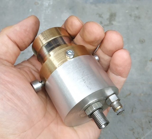
 After removing the wire from the drum and removing the manufacturing allowances, I obtained 2.1 m of the semicircular profile I needed. I think that with a little modification to the drum, it could also be used to produce a square profile.
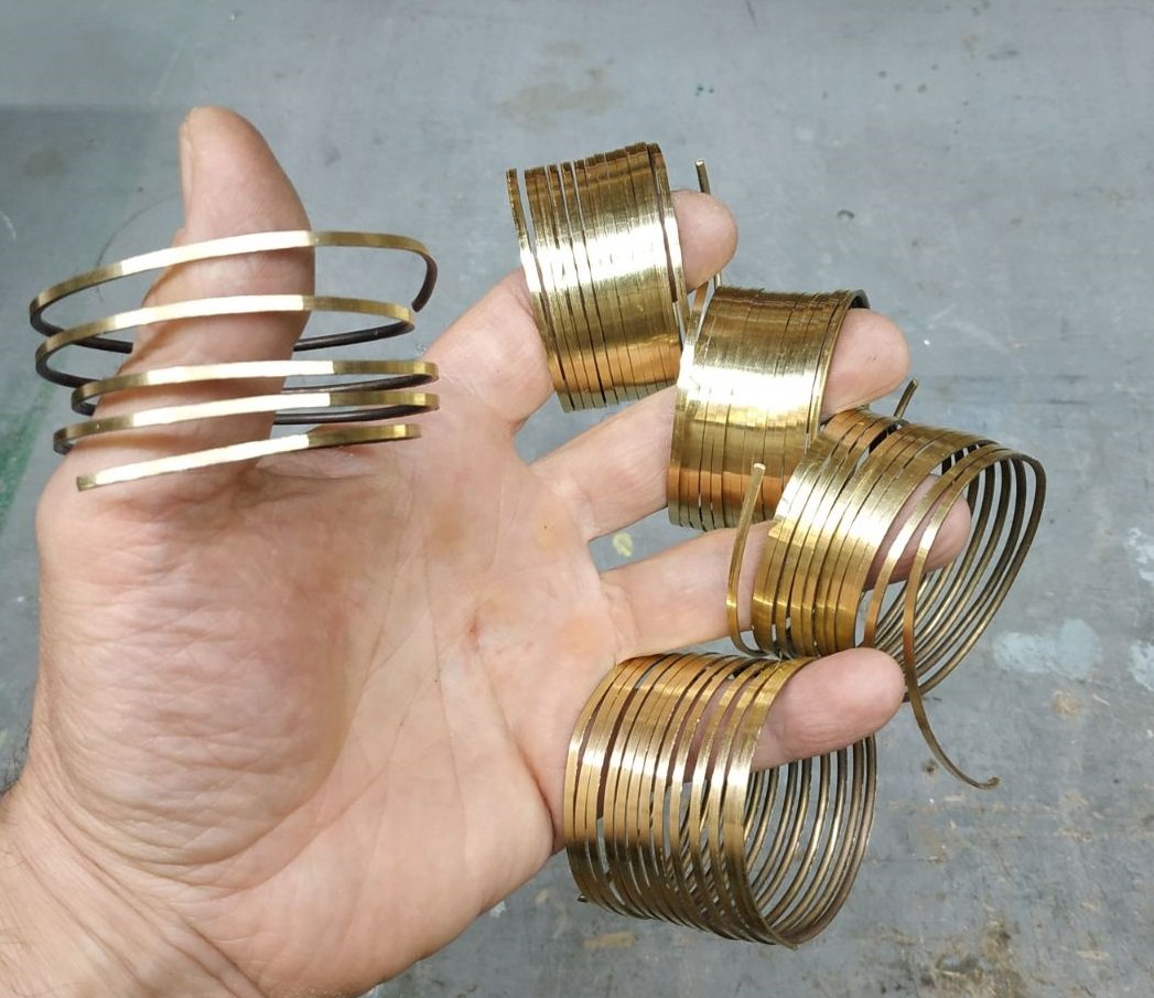
-
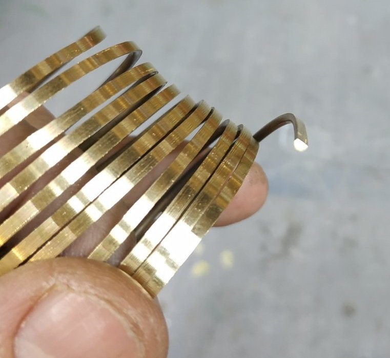
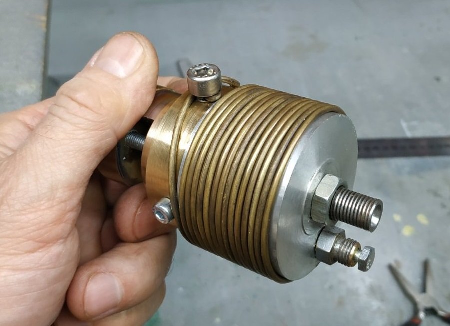
After being sharpened with a cutter, the wire on the drum took on this appearance.
-
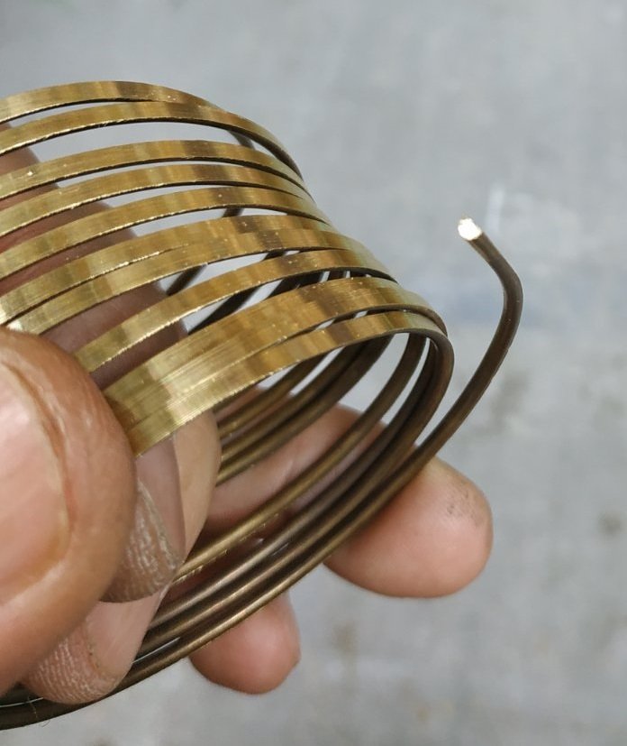
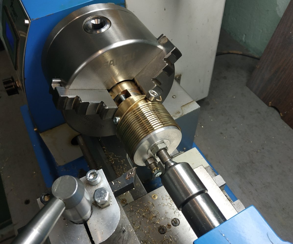
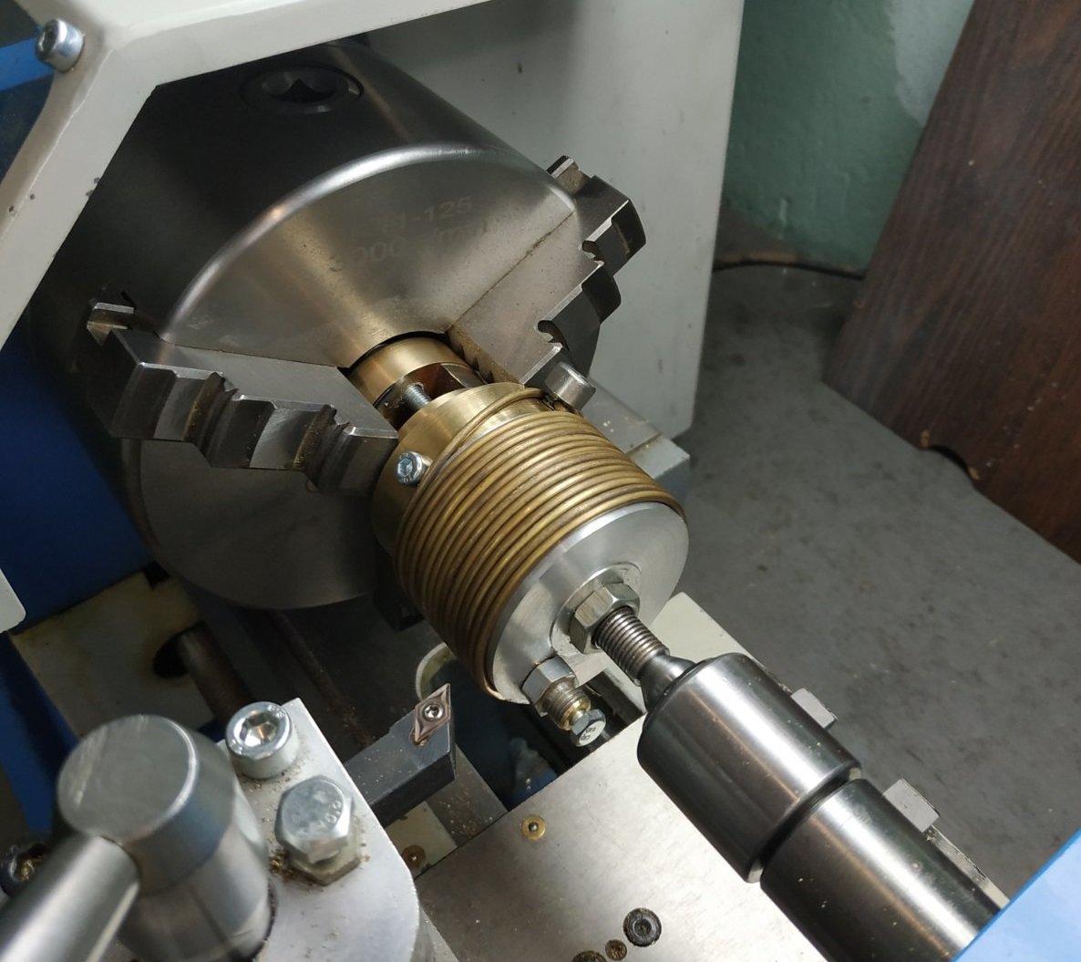
Then I wound it with 2 mm diameter wire and inserted the drum into the lathe. The length of wire that fit onto this drum was 2.3 m.
-
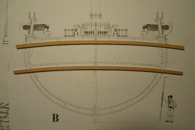
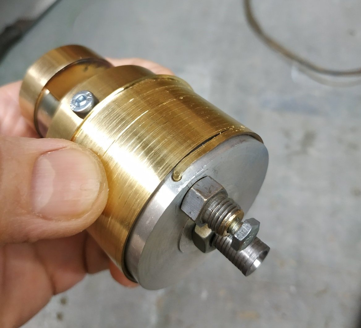
Hello everyone! Today I'll share a method for making a semicircular brass profile. Perhaps this will be useful for someone building models. The simplest way to create a semicircle is with a jewelry die. However, when the wire diameter increases beyond 1.5 mm, significant physical force or a special drawing mechanism is required. I decided to make my life a little easier and made this drum.
-
 archjofo reacted to a post in a topic:
Napoleonic Era Miniatures by Thukydides - 1/700 & 1/1200 - 3D-Printed Hulls
archjofo reacted to a post in a topic:
Napoleonic Era Miniatures by Thukydides - 1/700 & 1/1200 - 3D-Printed Hulls
-
archjofo reacted to a post in a topic:
Napoleonic Era Miniatures by Thukydides - 1/700 & 1/1200 - 3D-Printed Hulls
-
archjofo reacted to a post in a topic:
Napoleonic Era Miniatures by Thukydides - 1/700 & 1/1200 - 3D-Printed Hulls
-
archjofo reacted to a post in a topic:
Napoleonic Era Miniatures by Thukydides - 1/700 & 1/1200 - 3D-Printed Hulls
-
archjofo reacted to a post in a topic:
Napoleonic Era Miniatures by Thukydides - 1/700 & 1/1200 - 3D-Printed Hulls
-
archjofo reacted to a post in a topic:
LA CREOLE/ LA GUADELOUPE by matiz - 1:48 - by Tiziano Mainardi from Boudriot plans
-
Valeriy V reacted to a post in a topic:
M/V Pobjeda 1958 by Deutz_RVBM_545 1958 - 1:100 - RADIO
-
Valeriy V reacted to a post in a topic:
USS Cape (MSI-2) by Dr PR - 1:48 - Inshore Minesweeper
-
 Valeriy V reacted to a post in a topic:
USS Cape (MSI-2) by Dr PR - 1:48 - Inshore Minesweeper
Valeriy V reacted to a post in a topic:
USS Cape (MSI-2) by Dr PR - 1:48 - Inshore Minesweeper
-
Valeriy V reacted to a post in a topic:
USS Cape (MSI-2) by Dr PR - 1:48 - Inshore Minesweeper
- Today
-
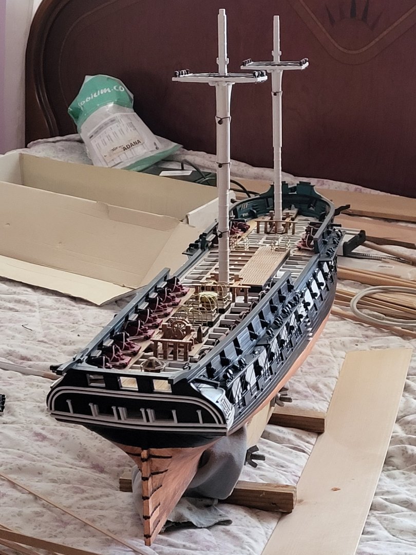
 Really like the overall dull colored look...it gives the ship an old impression
 -
 Be sure the silkspan is very dry before handling it! As I recall, on sailing ships the tablings along the edges of the sail were on the port side, and the larger corner reinforcements and other extra cloths were on the starboard. Will you add boltropes?
 -
Boat boom? We used long poles and buoys to mark locations - for mine fields, channels, etc. The spar passed through a hole in the buoy. On the lower end of the spar a cable and weight were attached to anchor the buoy. At the upper end of the spar was a flag (and a radar reflector after radar was invented).
-
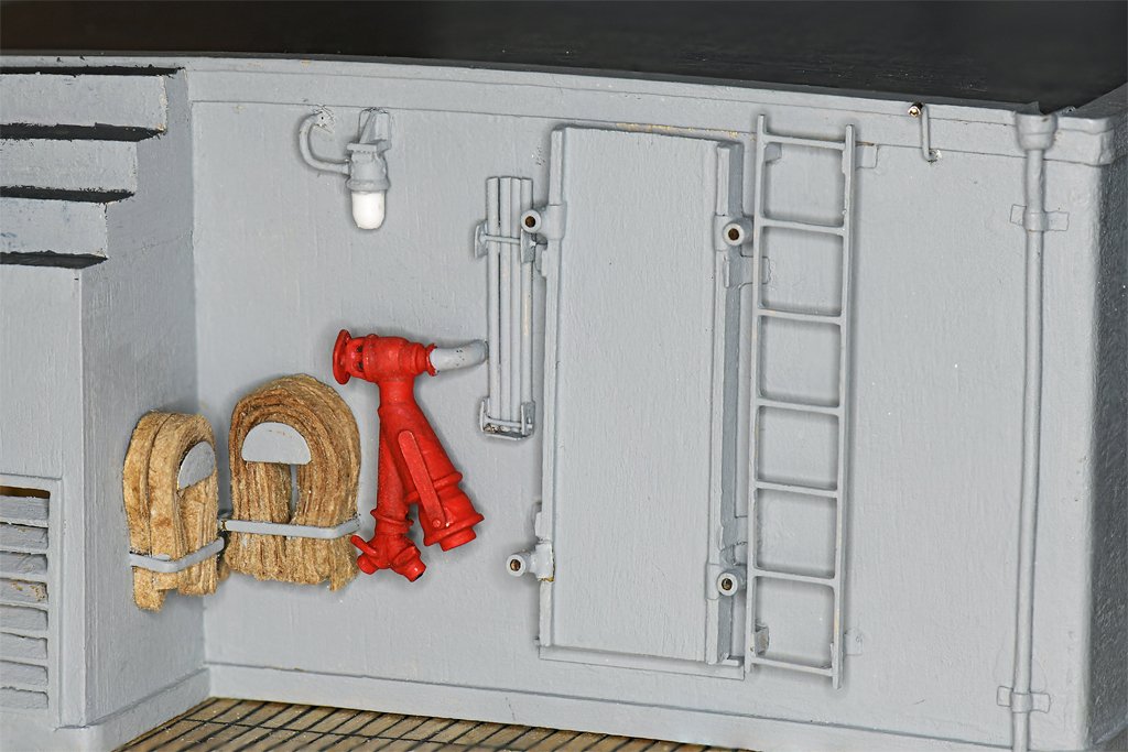
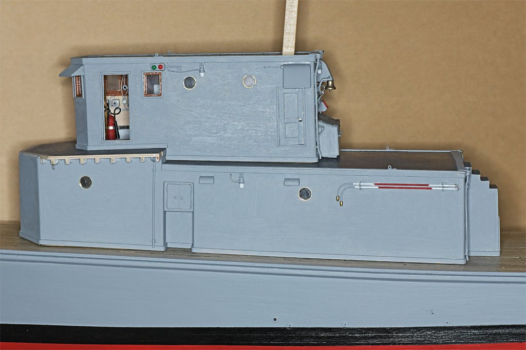
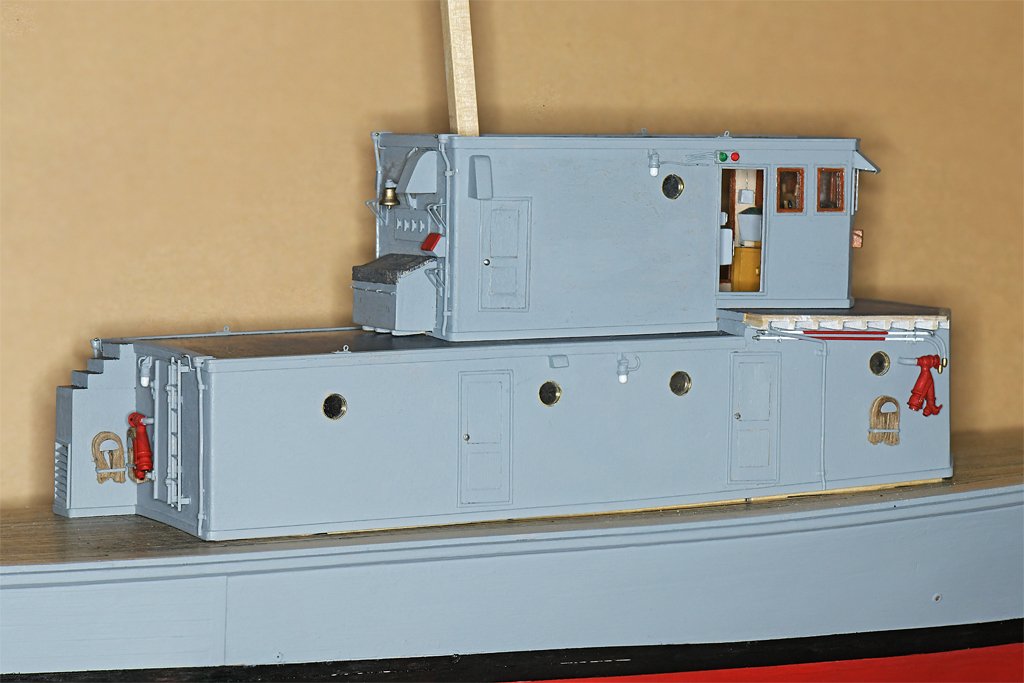
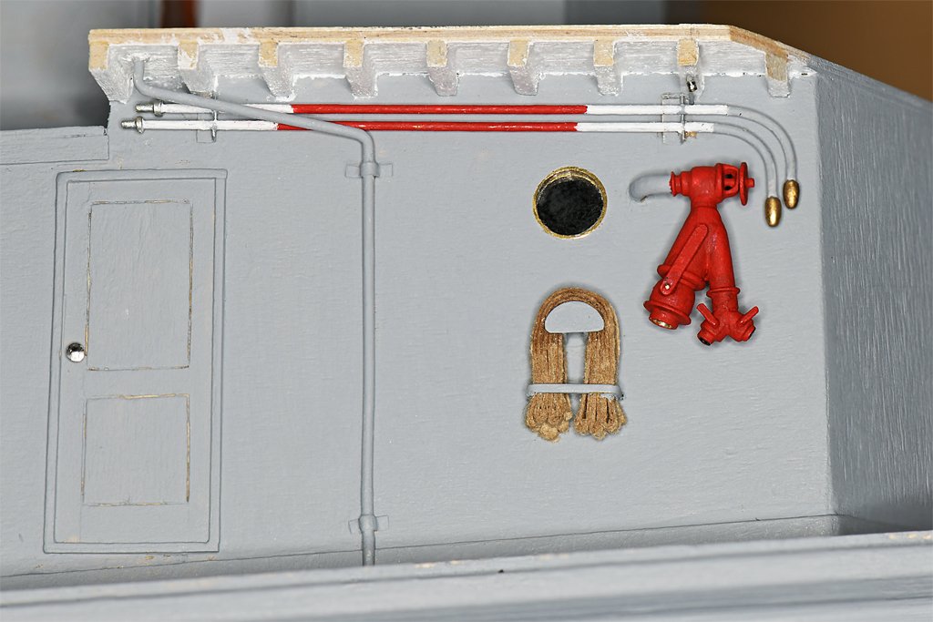
More details. These are probably the smallest details on the model. They are water washdown system spray heads. These are like the common indoor fire suppression system nozzles hanging from ceilings. They should have a base plate with four arms curving up to hold a spray deflection cone. But at less than a millimeter (0.039 inch) long and wide that isn't going to get modeled! The pipe was half inch inside diameter, so it was about 3/4 inch (19 mm) outside diameter. I used 0.015 inch (0.4 mm) brass rod for the 1:48 scale pipe. The nozzles are short pieces of 23 gauge hypodermic needle tubing. Navy ships have washdown sprayers all over the topsides. If the ship is attacked with CBR weapons (chemical, biological or radiological) the washdown system is activated to wash contamination overboard. It would also be used if the ship sailed through fallout from nuclear blasts. You may have seen photos of ships steaming through a local cloud of fog - that would be the washdown spray. I have been installing lots of small details on the deck houses. Lights, ventilation hoods, firefighting equipment and the washdown sprayers. This is the aft end of the main deckhouse. You can see one of the washdown sprayers at the upper right. The ladder is positioned below where there will be a gap in the life rails around the O1 level. To the left of the ladder is where the brow and it's stanchions are stowed. One of the two topside fire fighting stations is here, with the hydrant/strainer, two 2 1/2 inch (63 mm) hoses, and two 1 1/2 inch (38 mm) hoses. Extension pipes with "spud" tip sprayers were mounted on the aft port side of the deck house. The spud tips were a brass ovoid with many small holes. Water sprayed out in a fine sheet of low velocity water fog. This was effective for suppressing flames. Here is the second fire fighting station on the forward side of the main deckhouse. In addition to the hydrant/strainer and two fire hoses, there are two extension pipes with spud tips stowed above. Look closely and you will see another washdown nozzle below the deck beams over the hydrant/strainer.
- 368 replies
-
- 3
-
-
-
- minesweeper
- Cape
- (and 1 more)
-
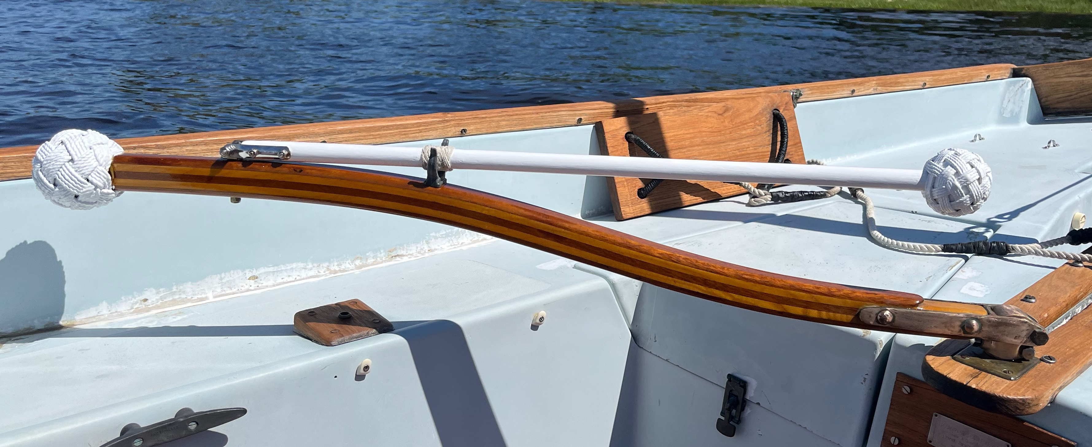
 Very nice work personalizing the tiller! As to your point about accuracy to a specific ship vs. accuracy to a generic type, I have to admit that I prefer the latter style. Figuring out the range of possibilities and choosing which option I want to depict and why seems more fun than trying to pin everything down to exactly how it was, at least at the moment. Who knows, though, maybe after a few more builds I'll change my mind.
 -
 A really long youney comes to an end. It was a great pleasure to follow your log over the last years.
 -
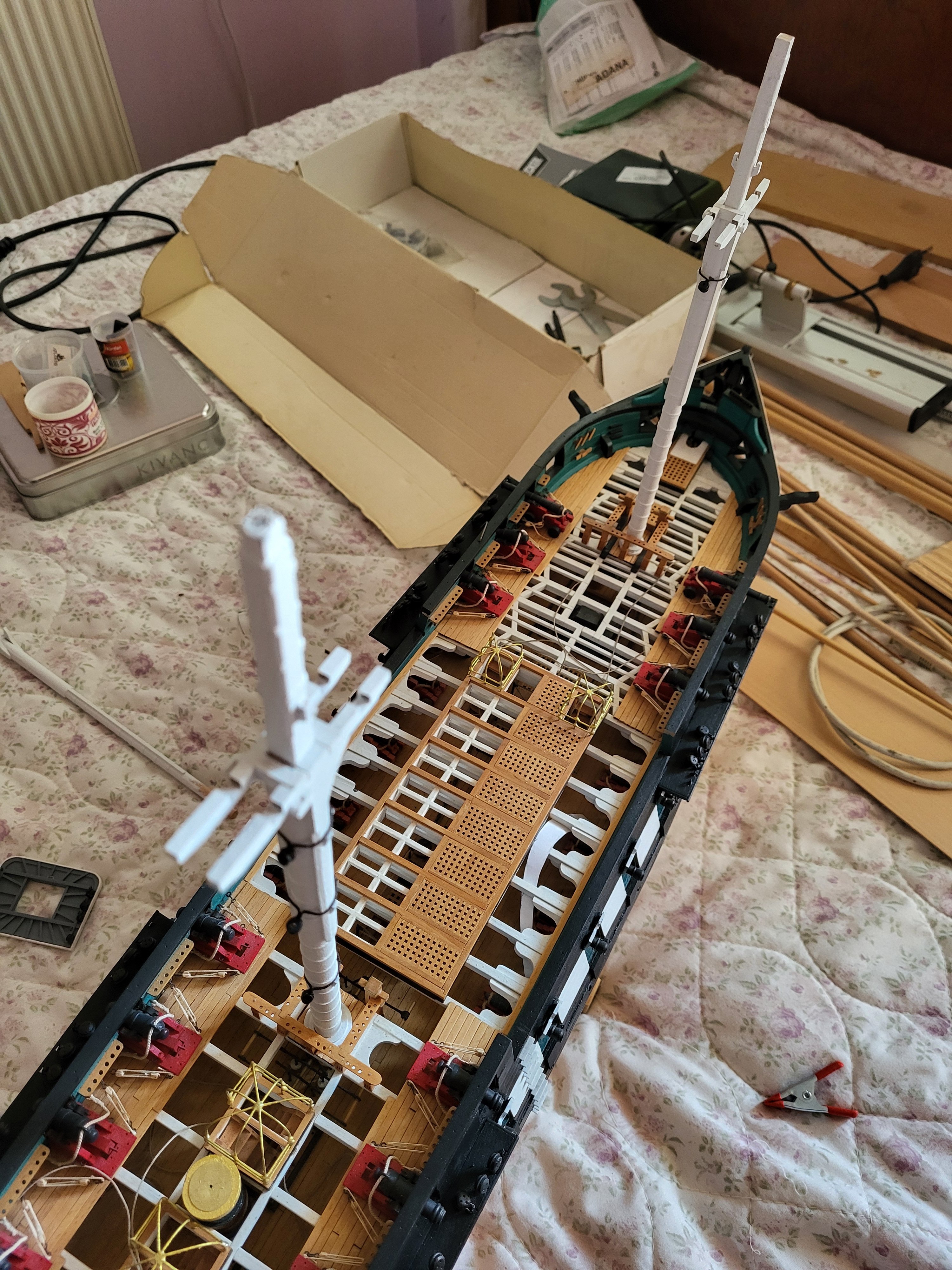
 I settled on carving the knightheads myself. Now, 22 tiny carved knightheads later, I'm done with all the ones that attach to the rail. Of course, the metal front railing doesn't fit, so I'm carving that too. And I'm probably going to carve the 8 additional knightheads that go near the masts. They're simple to do. All you need is a sharp X-Acto knife and a lot of persistence. I also put a thin veneer over the false deck at the bow and the stern. It looks much better. Hopefully this phase will go much more quickly after I'm done with the ridiculous amounts of tiny carvings. At least I've preemptively assembled the gun carriages. Also, if anyone can provide photos of where all the cleat hitches attach, I would be very grateful. I don't trust the kit drawings at this point.
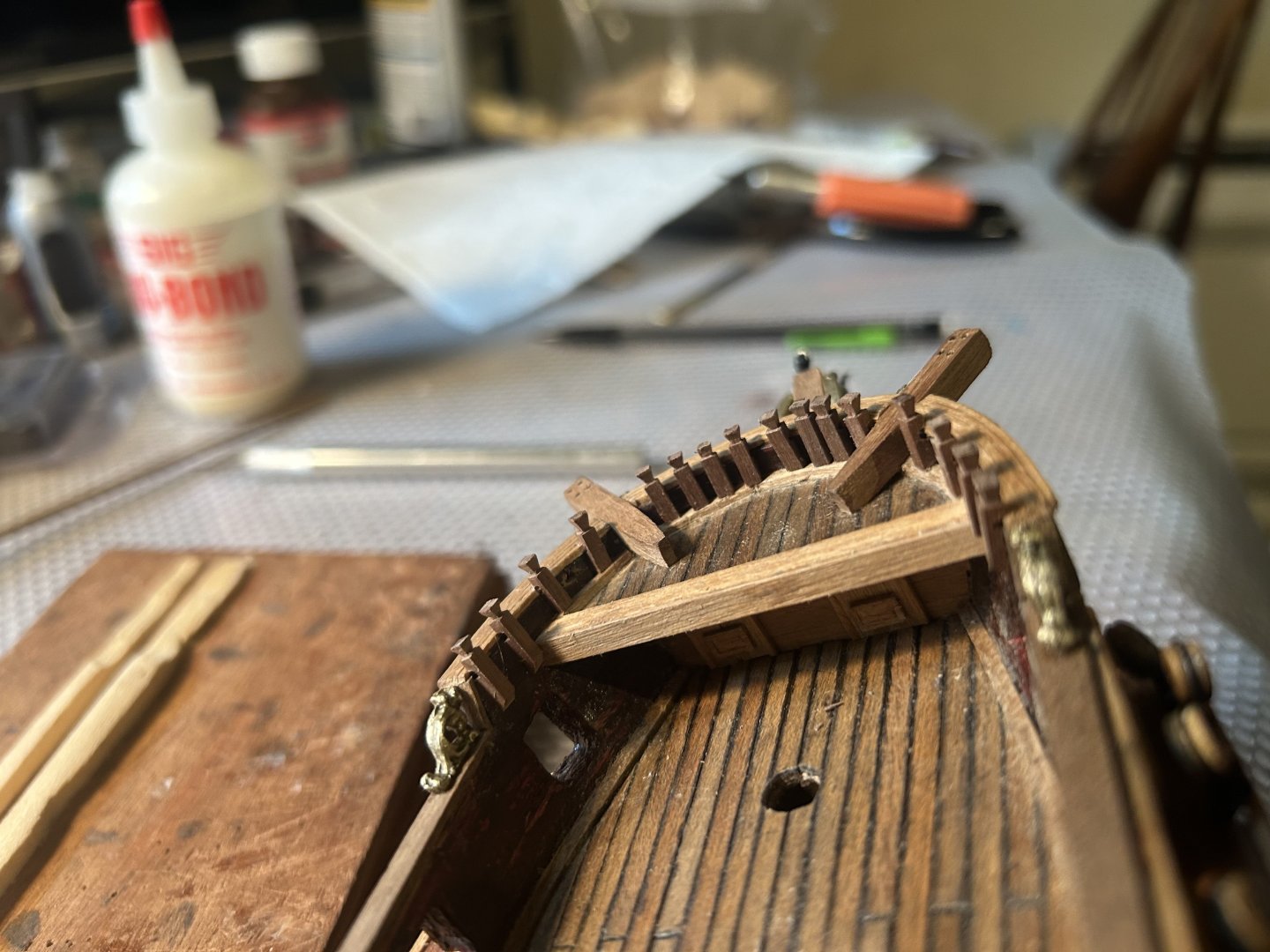

-

USS Constitution by mtbediz - 1:76
mtbediz replied to mtbediz's topic in - Build logs for subjects built 1751 - 1800
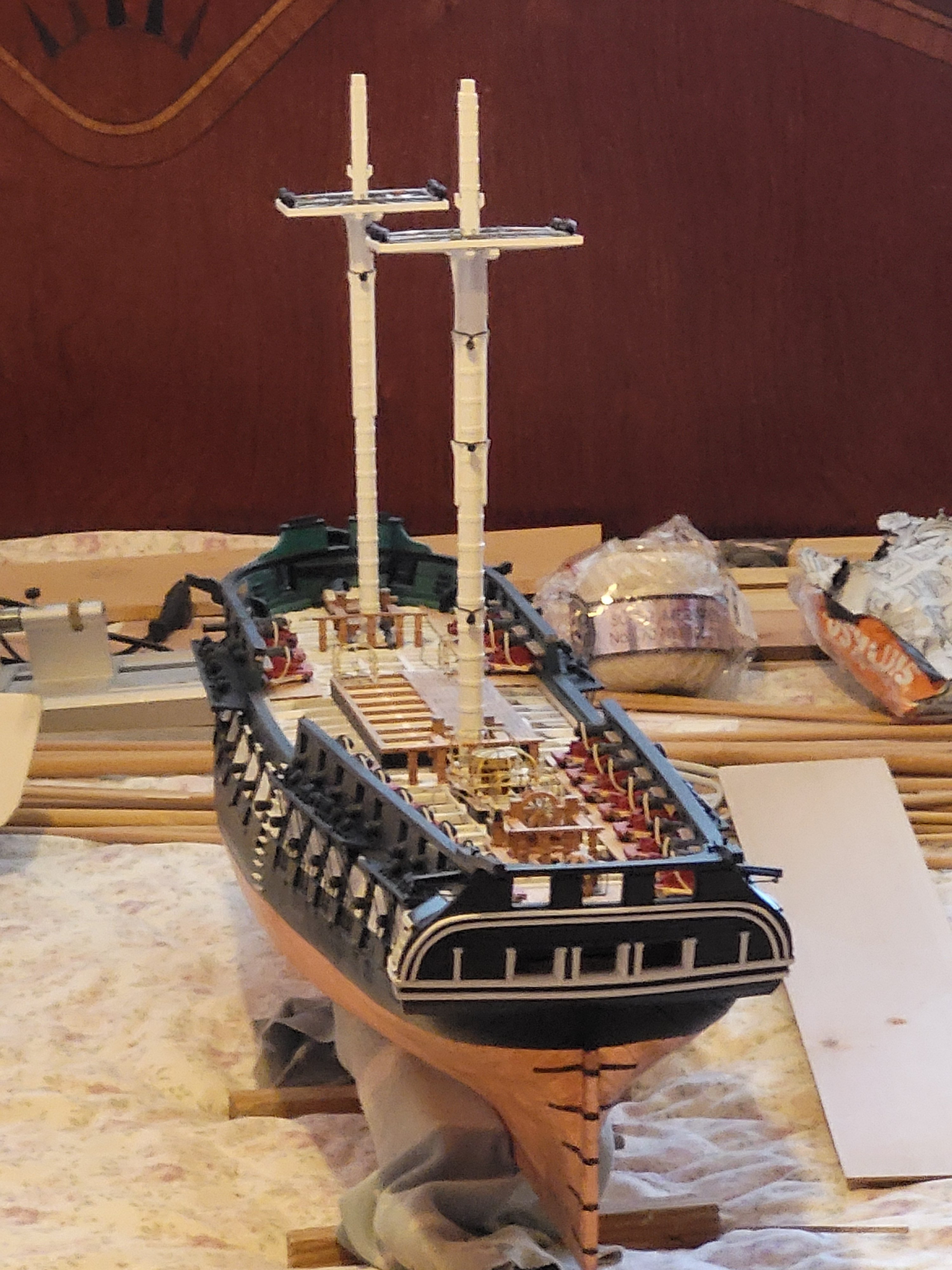
Thanks, Greg. I plan to build all the boats and put them in place. I think I'll make the ones on the main hatch unfixed so they can be removed if needed. -
USS Constitution by mtbediz - 1:76
GGibson replied to mtbediz's topic in - Build logs for subjects built 1751 - 1800
Fantastic work, Mustafa! It's obvious that you put your milling machine to a lot of work making everything fit together perfectly. And I love the pictures that are (once again) showing the open spar deck and exposed gun deck. This is what I hope to shoot for with my Constitution. That last picture reminded me to ask you, though, are you eventually intending to place boats on the main hatch or leaving them off to help keep exposed as much of the gun deck details as possible? Curious... -
 Ian, wild guess here.......were those spars used to deploy the torpedo nets (removed after the Battle of Jutland in 1916) and the "barrels" (which have domed tops) held the netting?
 -
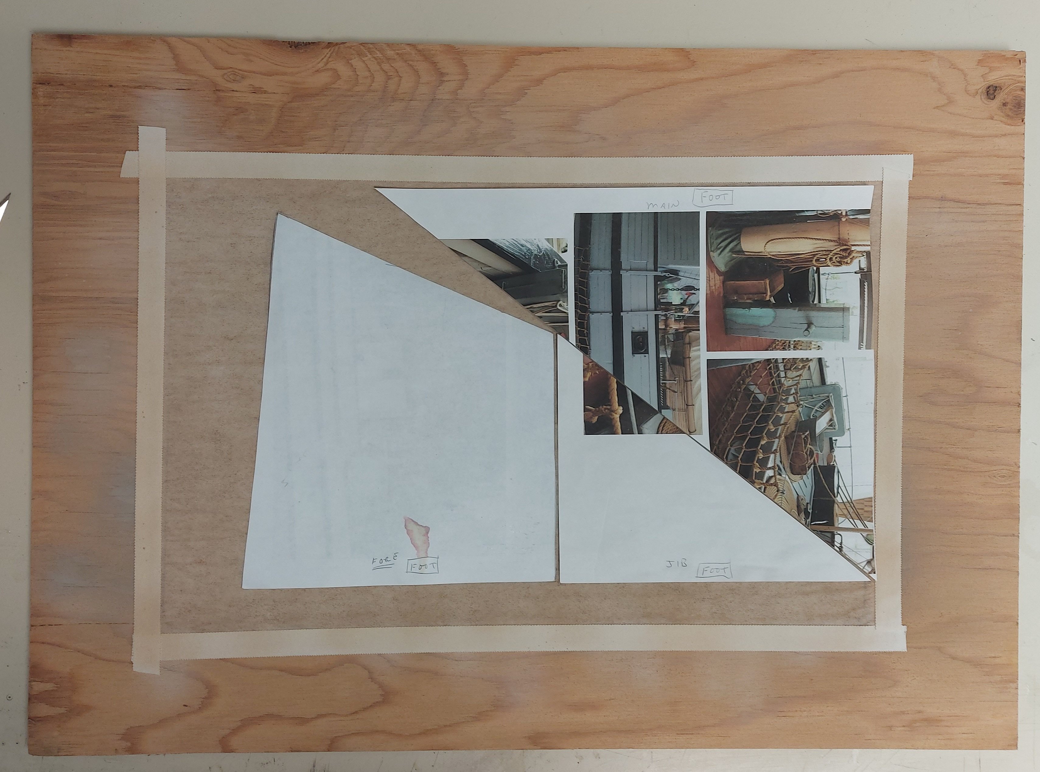
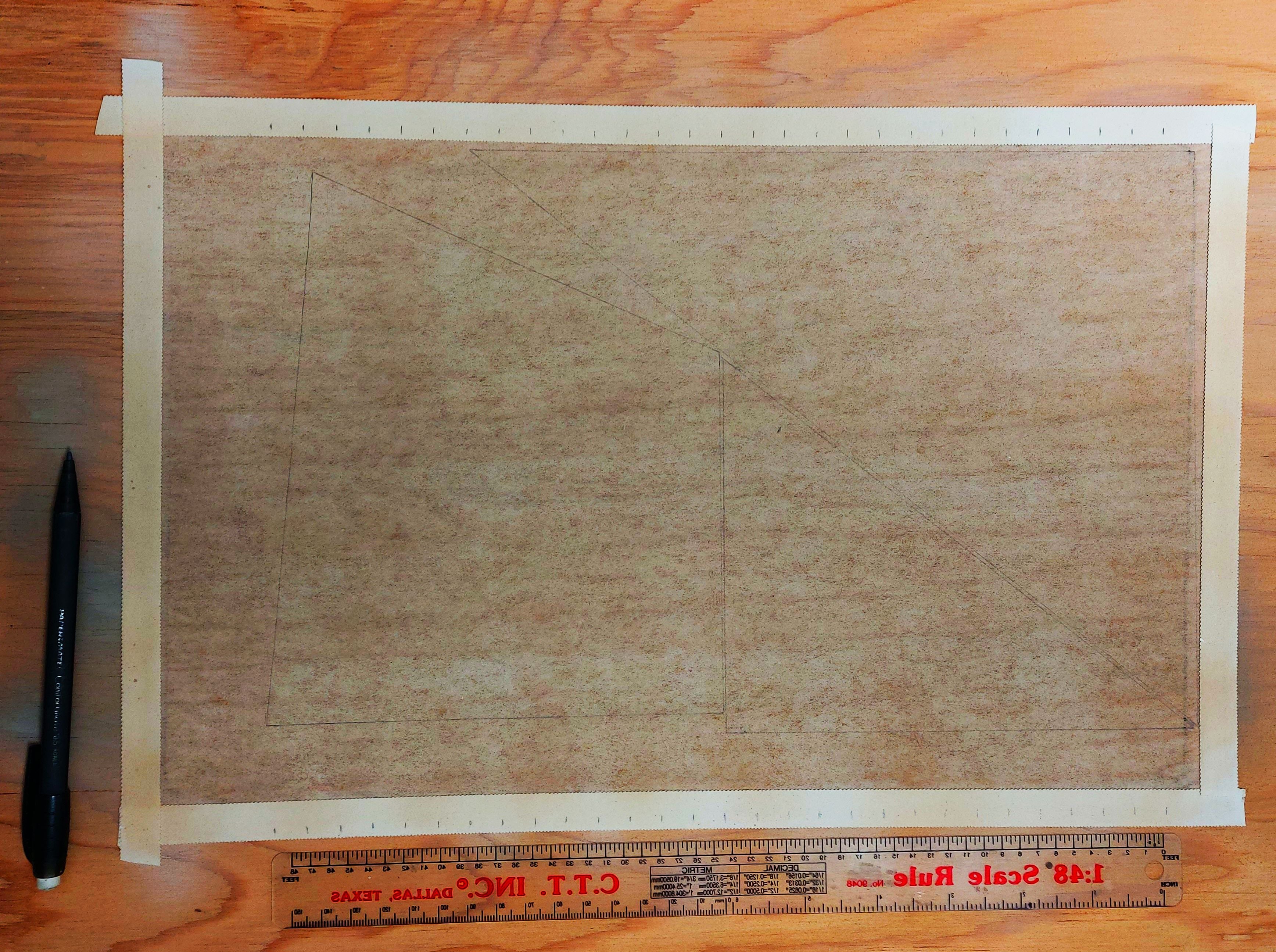
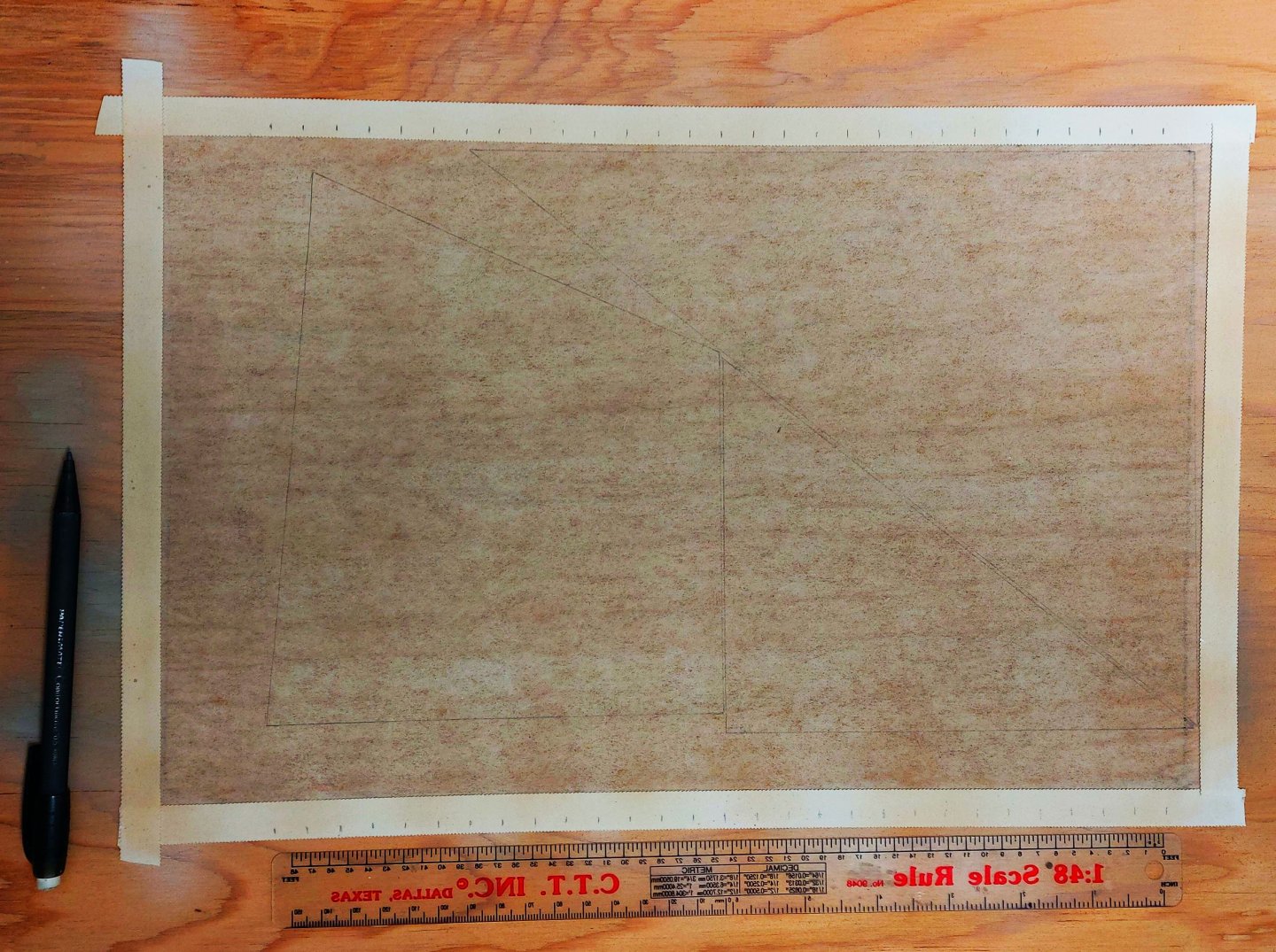
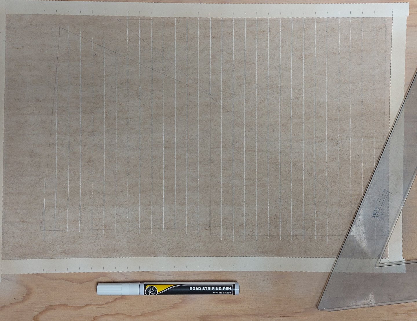
 I have studied David Antsherl's appendix on sail making, and I previously made the recommended frame to hold the silkspan and practiced using it by making St. Roch's boat covers. First I taped the silkspan to the frame using medicinal tape from my first aid kit. This is waterproof and holds nicely. Then I thoroughly wetted the silkspan using a water spray through my air brush. After it had dried I airbrushed on flat white, followed by buff. While the paint dried I made paper templates of each of the three sails: jib, foresail, and main sail. They are about 30% reduced in height because I intend to furl them and I did not want them to be too bulky. Then I laid the templates onto the dried silkspan, trying to maximize the unused border areas as these will be used to make the tablatures and reinforcing panels. I aligned the foot of each sail so that when I drew the seams on I could use a single seam line that would cross each sail. Then I used a pencil to draw the outline of each sail onto the painted silkspan. At this point I deviated from Mr. Antsherl's process. For drawing the seam lines onto the sails he recommends a device called a 'Bow Pen' which is an old drafting implement. I actually have one in my Staedler 'Techmatic' drafting set that I used in my Electronic Technology course back in 1972! However, it is a very fussy device and even after practice drawing a straight line of consistent width and free of skips and blots is hard to do. I used a 'Road Striping Pen' made by Woodland Scenics. This is part of their system for making asphalt roads on model railroad layouts, and I also happen to have one of these! They are available in most decent hobby shops or on line for about $18 in either white or yellow ink. I made witness marks a scale 21 inches apart (the width of each sail cloth) along the top and bottom of my frame, lined up with the vertical side of my sails (the sides that will go up the masts). My template alignment worked out and I was able to draw seam lines from top to bottom across the three sails. Next up I may add another light spray of buff to tone down the seam lines and colour match them to the sail cloths. Mr. Antsherl says to add the tablatures and reinforcements at this point, but I will probably cut the sails from the silkspan first. My experience tells me it I will have an easier time adding these items off the frame, and besides, the material for these parts is coming from the extra silkspan at the side and bottom of the frame. So far so good... we'll see how I get on tomorrow... This is new territory for me so any comments are most welcome. Regards, Bruce
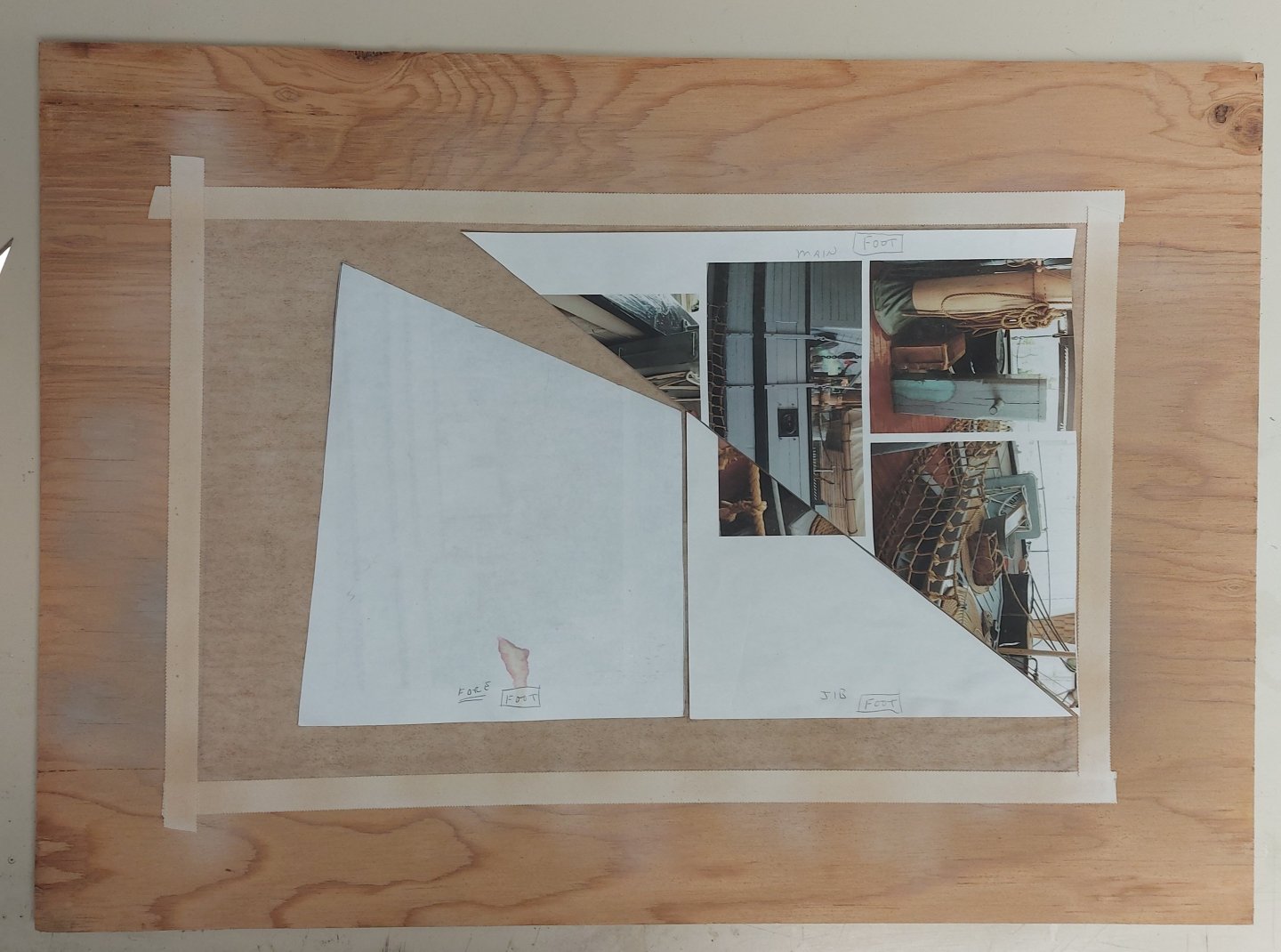
-

San Francisco cable car by kgstakes - OcCre
thibaultron replied to kgstakes's topic in Non-ship/categorised builds
If the real cars have them painted, I vote for that. -
 Congratulations, Henry, on the completion of your Swan class model. I believe you have incorporated every element included in our four volume series and, that in itself, is an amazing feat. Look forward to those final photos. Greg
 -
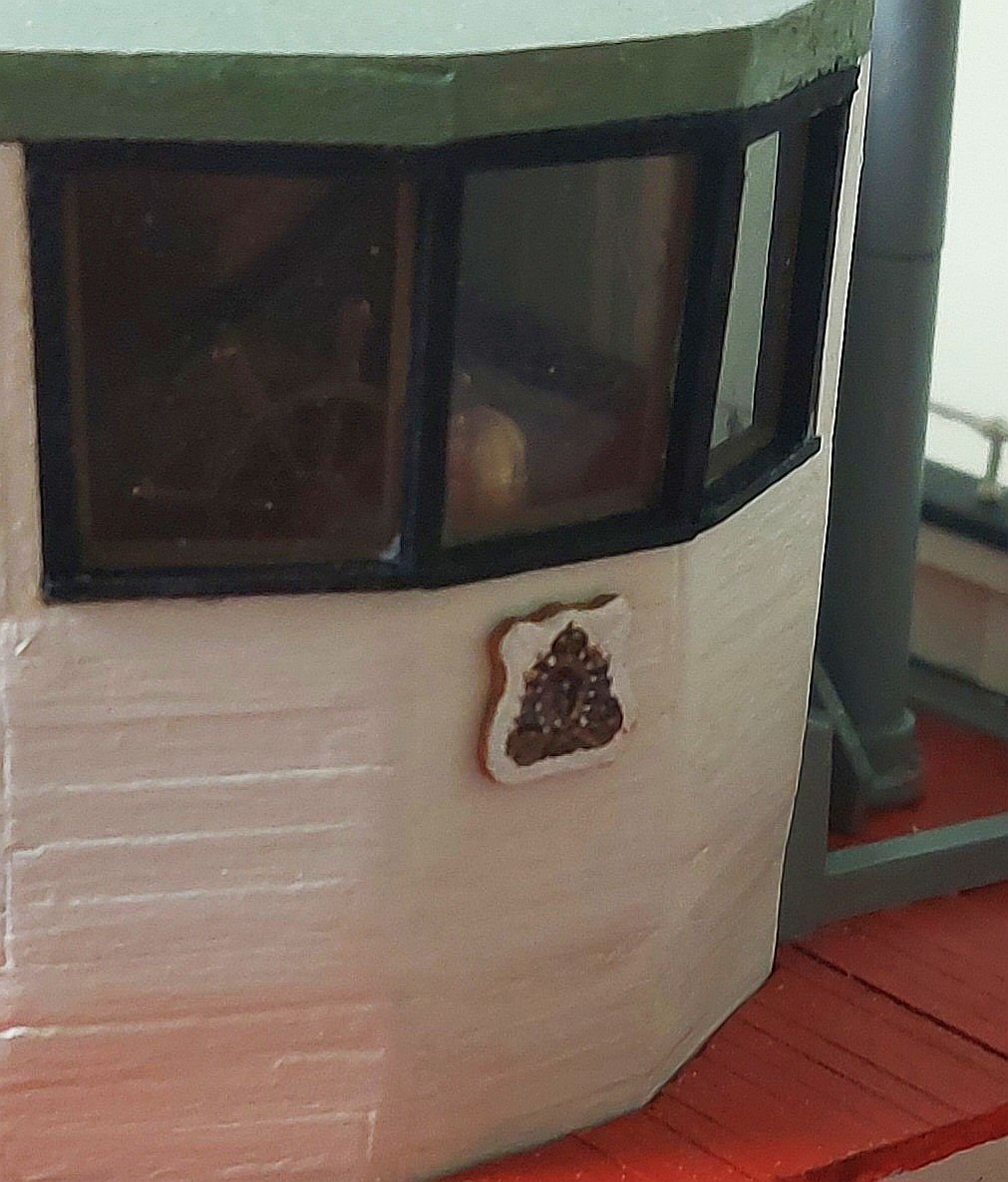
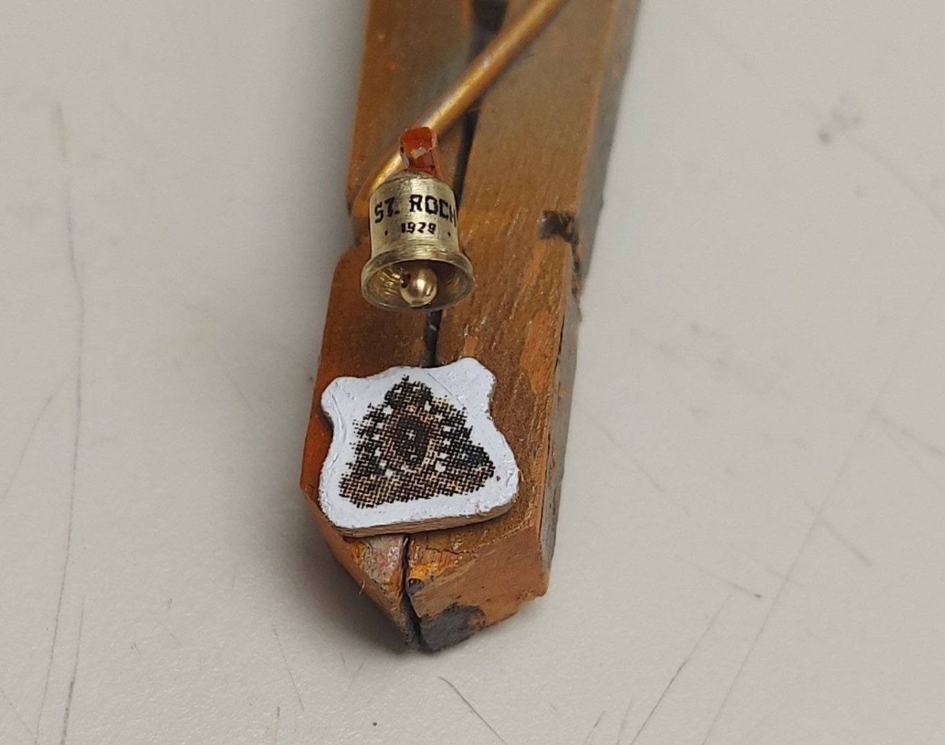
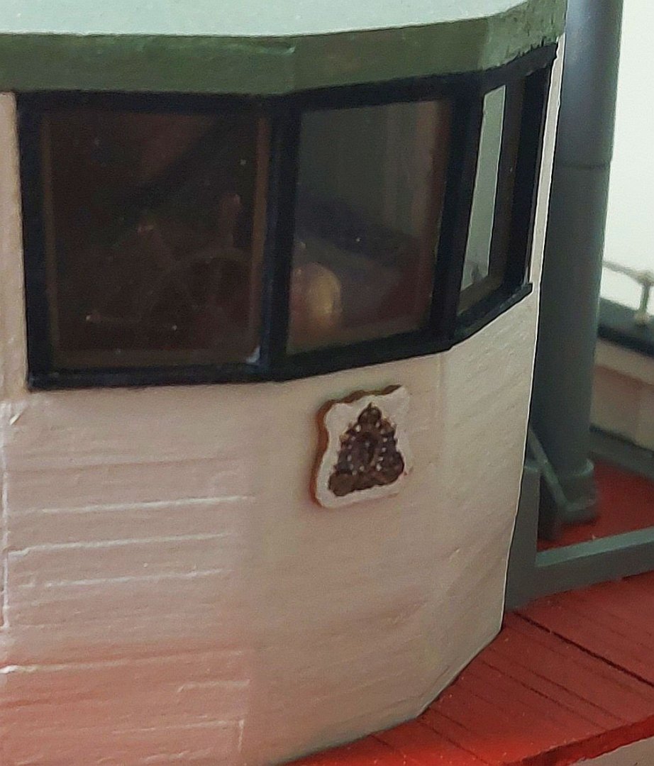
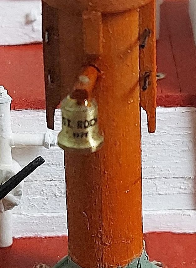
The day before Hallowe'en and we're ready for the spooky, candy filled debauchery! I have started sail making, and while waiting for the silkspan to dry I made up a couple of miscellaneous details... I turned St. Roch's bell and carved out the plaque to hold the RCMP crest. The clapper is made from an old stanchion. The badge pixellated in my phone's macro mode, it looks better mounted on the wheelhouse front... Here is the bell mounted on the foremast... The numbers under 'St Roch' are 1928, the date of launching. Now back to the sails.
-
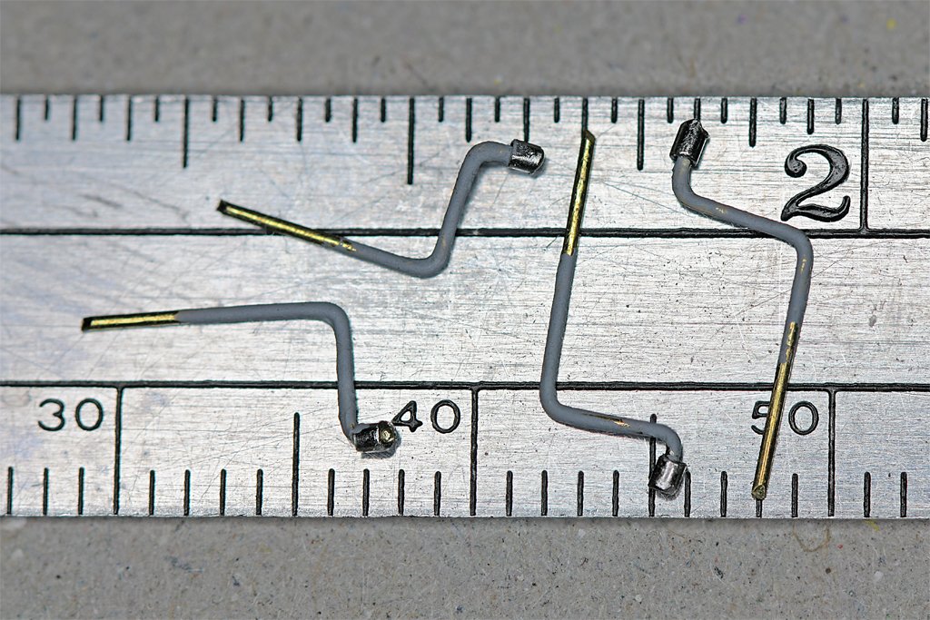
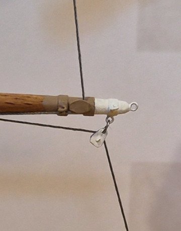
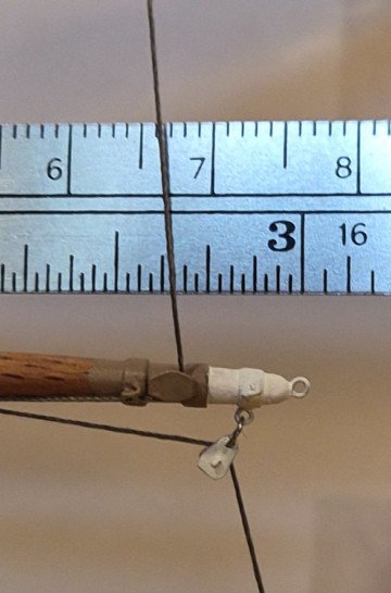
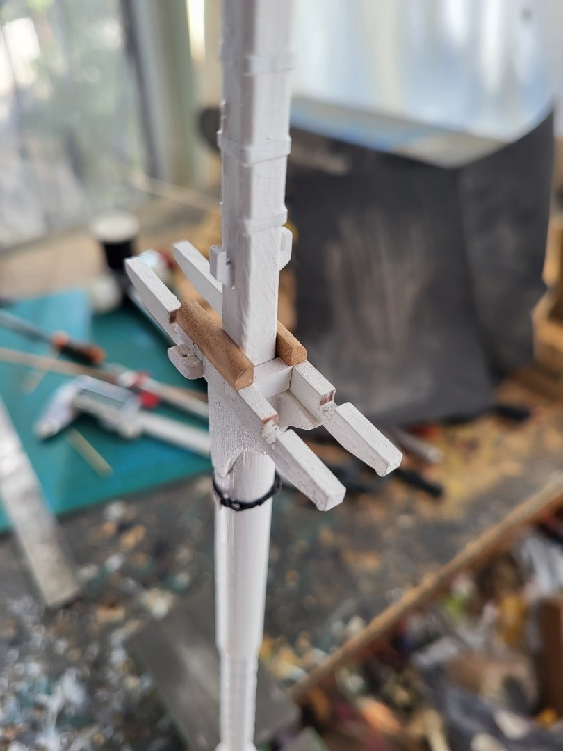
 As previously mentioned, the Eagle uses metal blocks for guiding wire ropes for sheets, clews, halyards, and braces. The working ends of the wire ropes eventually connect to wooden blocks that guide fiber ropes down to the deck for the cadets to handle. Below is what the upper topsail yard/yard arm looks like on the Eagle. I experimented with several methods of fabricating metal blocks like the two white ones shown in the photo (one for the clew, and the other for the brace), and settled on using pieces of sheet aluminum for the sides, a piece of a straight pin for the axle, and a loop of wire sandwiched between the sides and around the axle for the sheave. I used CA to glue all the pieces together. It's not intended to be a working block, just to look like one. I drilled a hole at the end for use in connecting the block to either an eye attached to a yard, or to another wire rope (or in the case of some of the braces, a piece of wire simulating a length of metal bar). I'll be using gray thread to replicate the wire rope. I made several sizes of blocks, wanting to keep as close as possible to the scale size of the actual blocks. I estimated the smallest ones (which is the majority of the blocks) are between 6 and 9 inches long, so to scale would be 1/16" to 3/32". I was able to make decent ones at 3/32" but the attempts at 1/16" were unacceptable. The largest ones will be 1/8". I previously developed a method, in post #28, for making the sheet sheeve that is attached directly to each yard, as shown in the photo above. I decided to make a test yard/yard arm with the metal blocks, sheet sheeve, and attachment points (eyes) for the brace, foot rope, and Flemish horse. I omitted the eye on the top end of the yardarm, and haven't decided yet on how to replicate the jackstays on top of the yard. The photos below show my test yard/yard arm (which is suspended by the arms of a Quad Hands, not visible in the photo). The size of this test yard is actually a bit smaller than the size of the royal yard, so I should have no problem constructing all of the yards with the various attachment points. I ended up using thin blue masking tape for the metal bands around the yard at various places. The eyes are formed from 28 gauge wire and fastened using CA in hand-drilled holes. First I painted the yard/yard arm with two coats of shellac, lightly sanded, and then painted the yard arm and metal block white, and a portion of the yard light tan color (two coats of Testors enamel paint for each color; I'll probably go with a third coat for the actual model since the paint is still a little thin as is evident in the photo). For production, I'll use a color for the yard (and many other parts of the model) that is much closer to Coast Guard spar; True North Precision Paints has a color they show as an exact match, and I have some on order...will be testing once the order is received. I ran two threads on the test jig to approximate how the sheet (from the sail above) and the clew (for the sail attached to this yard) will show in the model. The hardest part of putting the parts together was attaching the metal block to the eye, using a small loop of 28 gauge wire. I'm happy with the overall look of the yard/yard arm, and especially of the metal blocks, so I'll continue making the ones I need (8 made so far, 62 to go). That's all for now. Lee
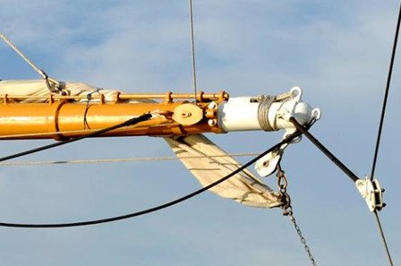
-
USS Constitution by mtbediz - 1:76
mtbediz replied to mtbediz's topic in - Build logs for subjects built 1751 - 1800
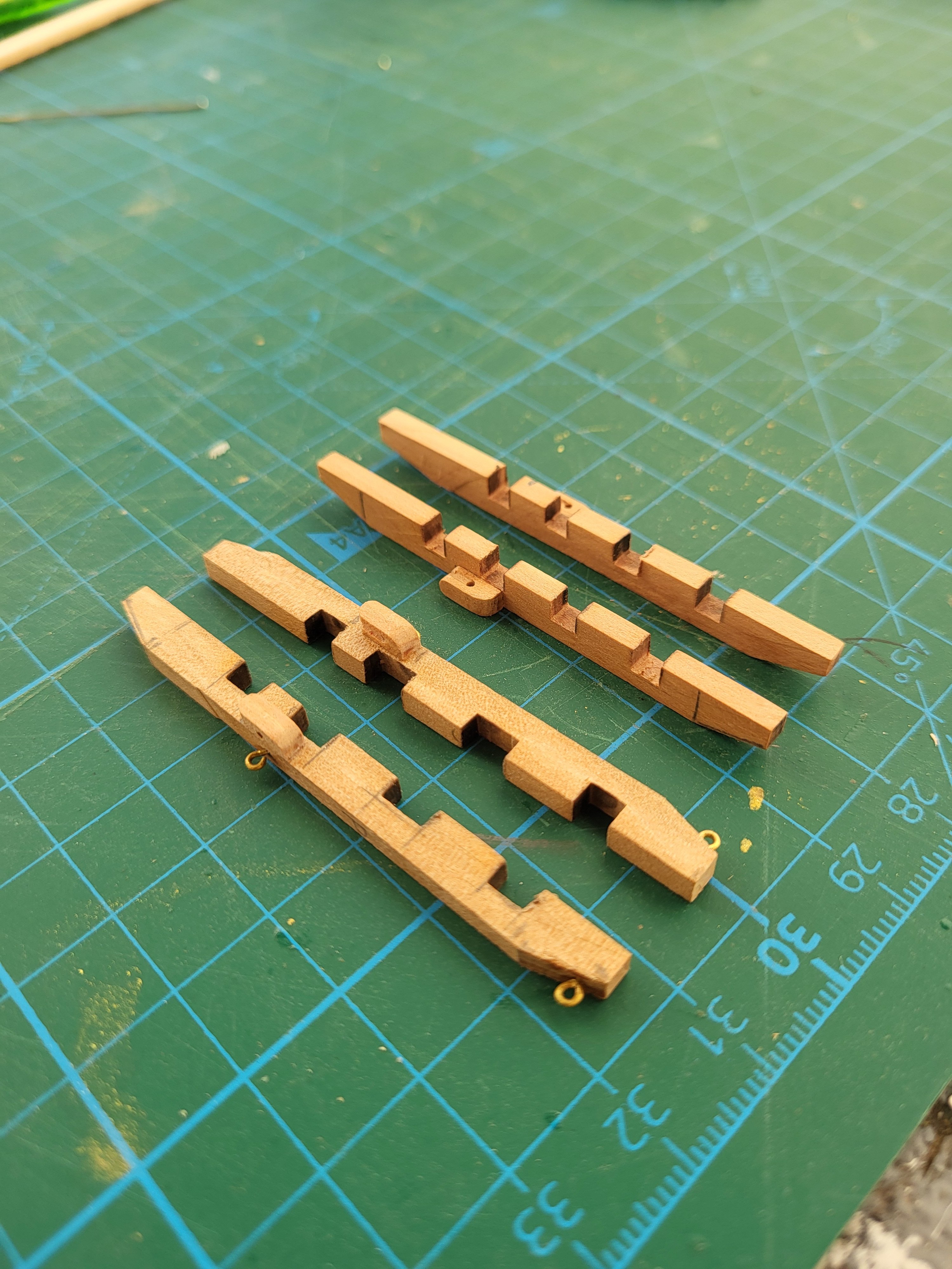
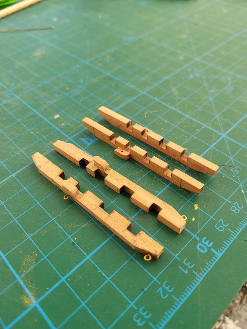
Thumb cleats, blocks with sheaves inside them, and bolsters were fabricated and fitted to the trestle trees today. As I always do, I drilled a small hole and a shallow channel to represent the sheaves. Once these fittings were in place, the main and fore trestle trees were glued to their respective masts. The platforms, however, have not yet been glued, they will remain separate until the shrouds are completed.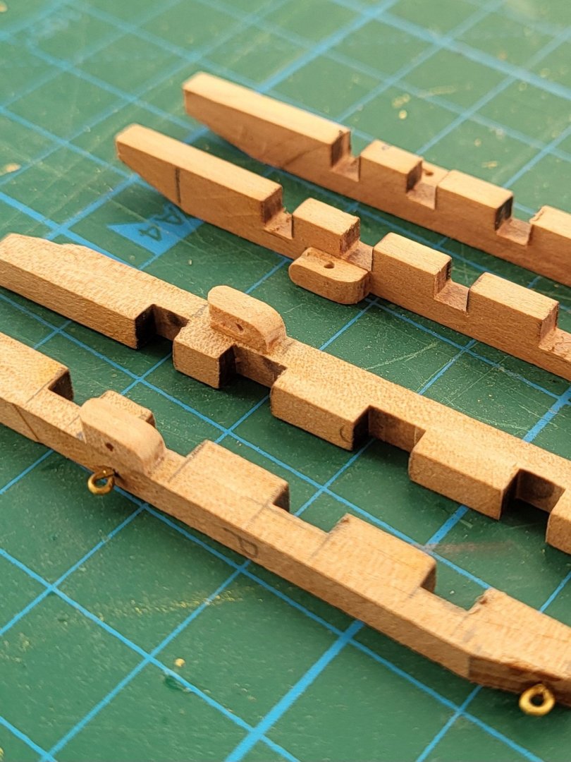


-
 Only three parts left after this!
-
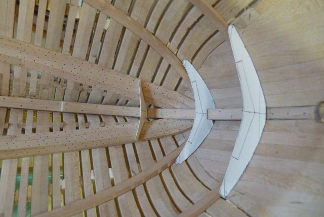
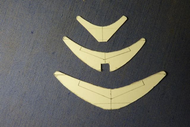
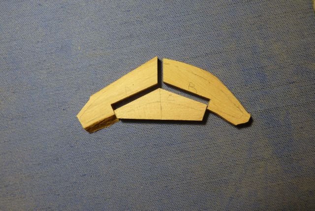
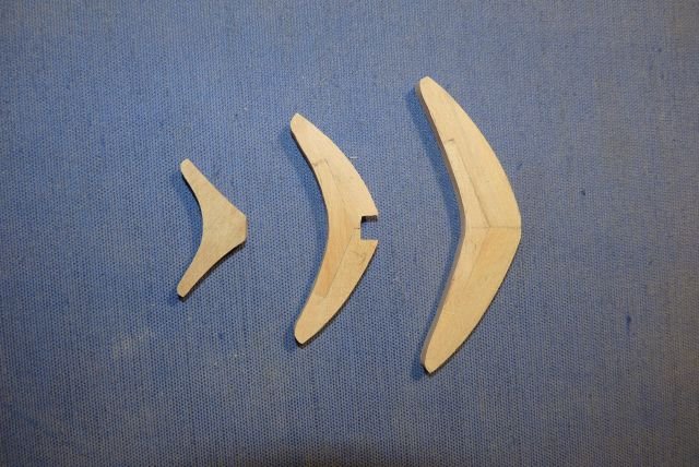
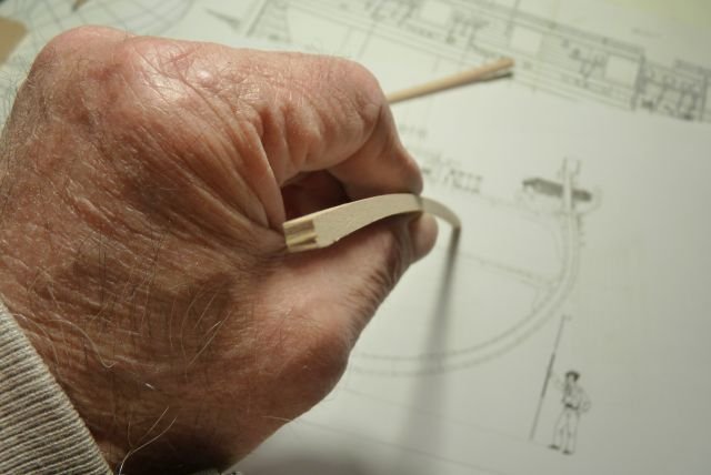
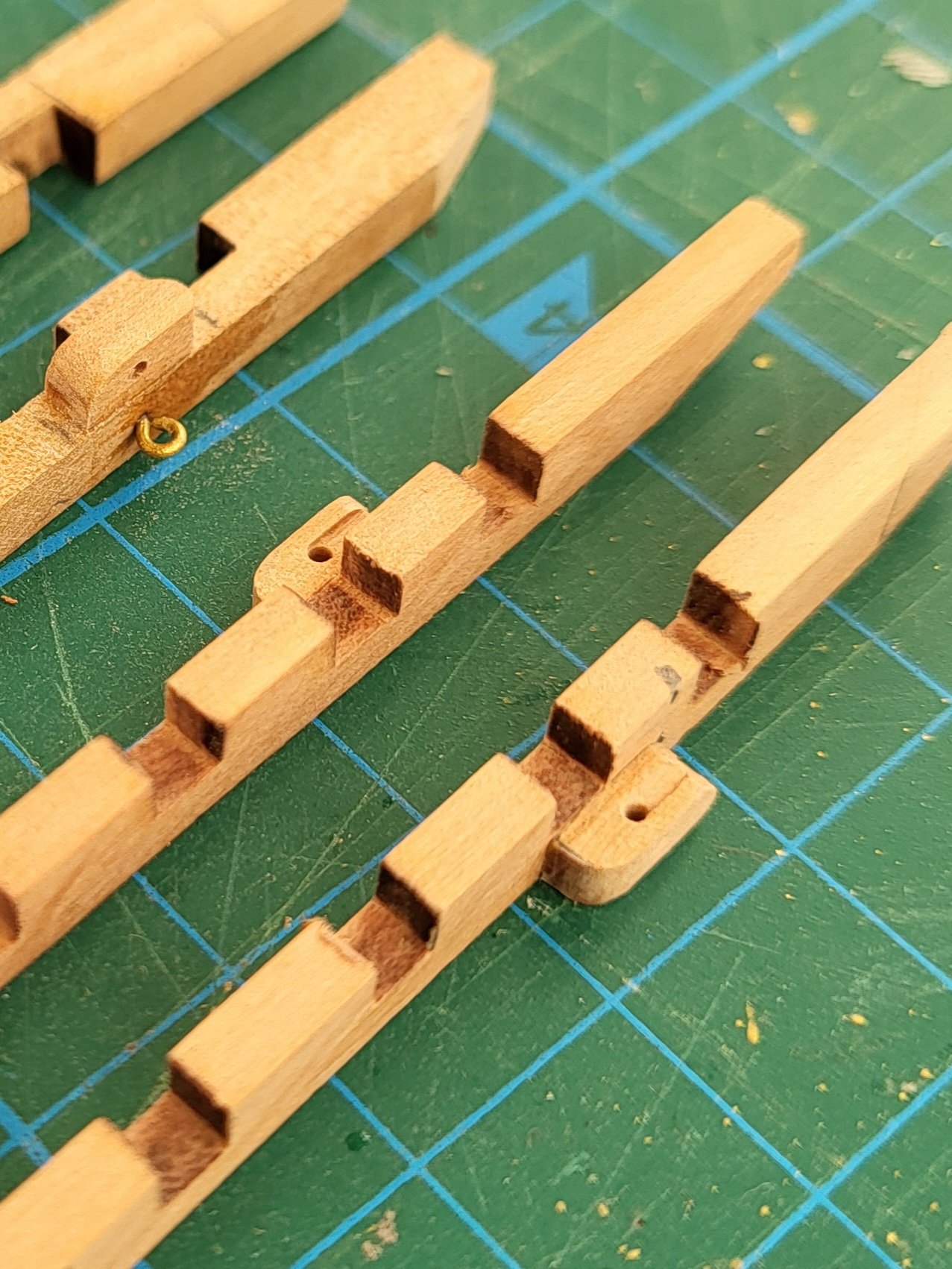
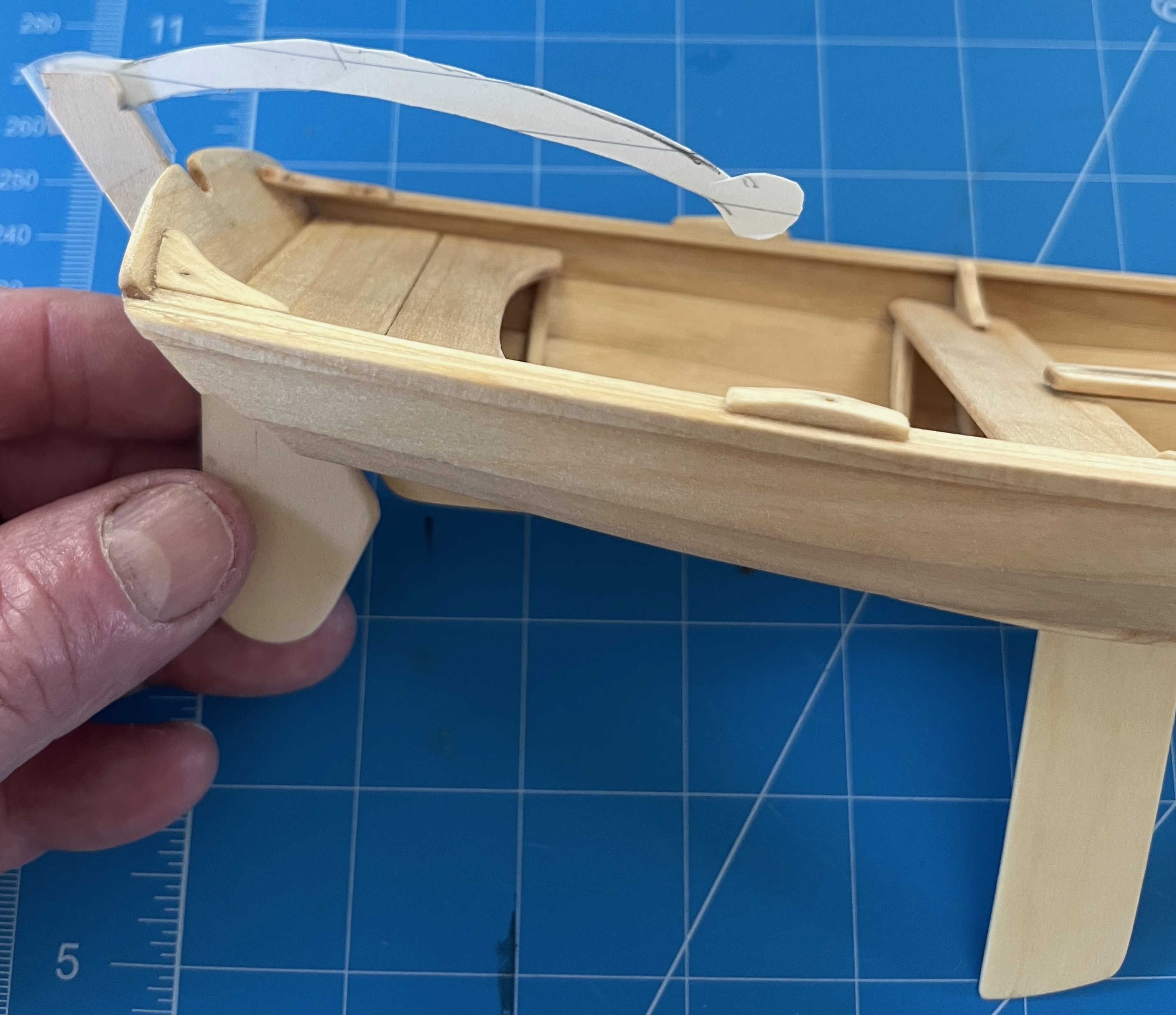
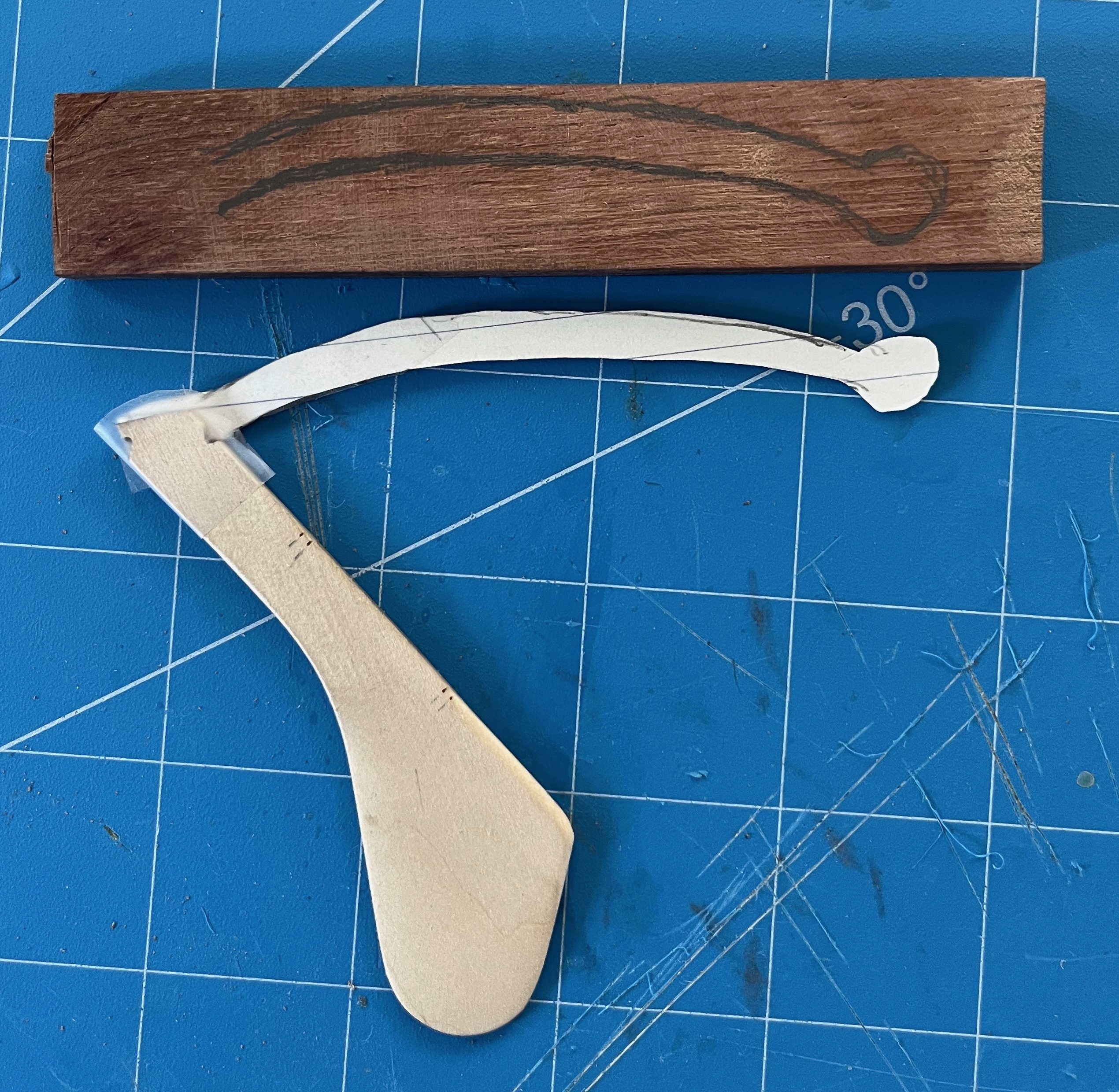
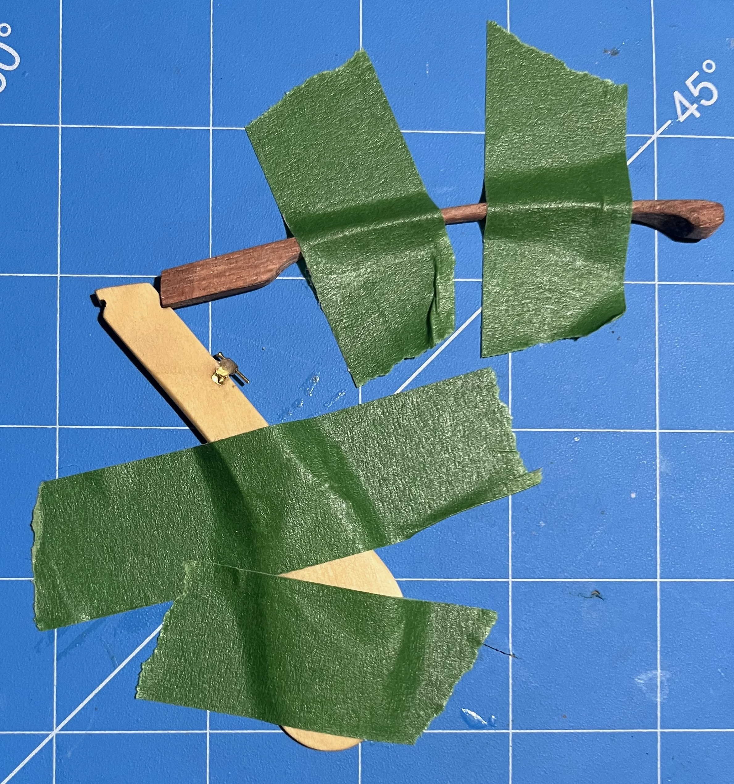
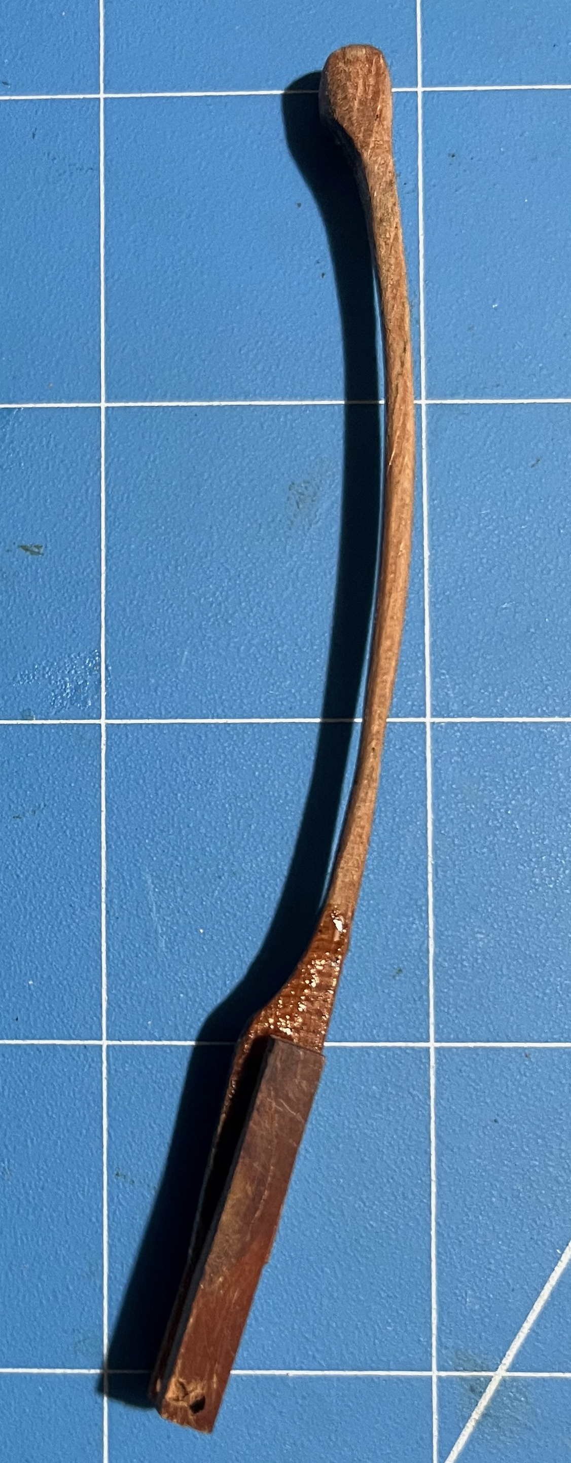
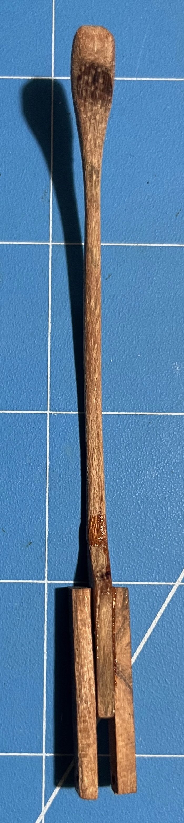
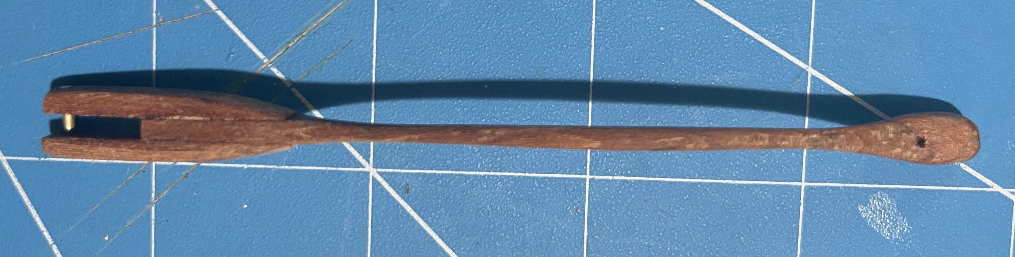
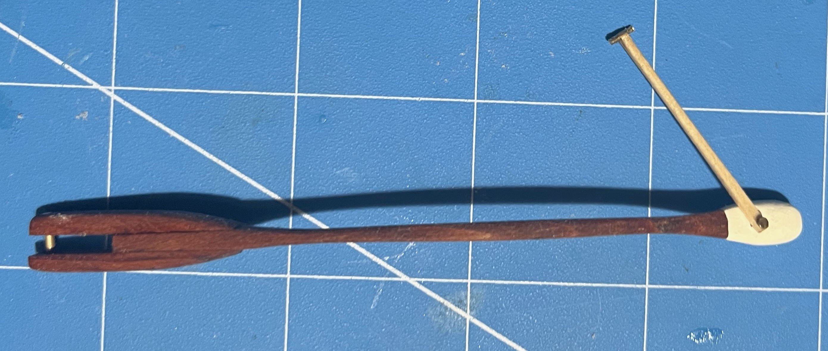
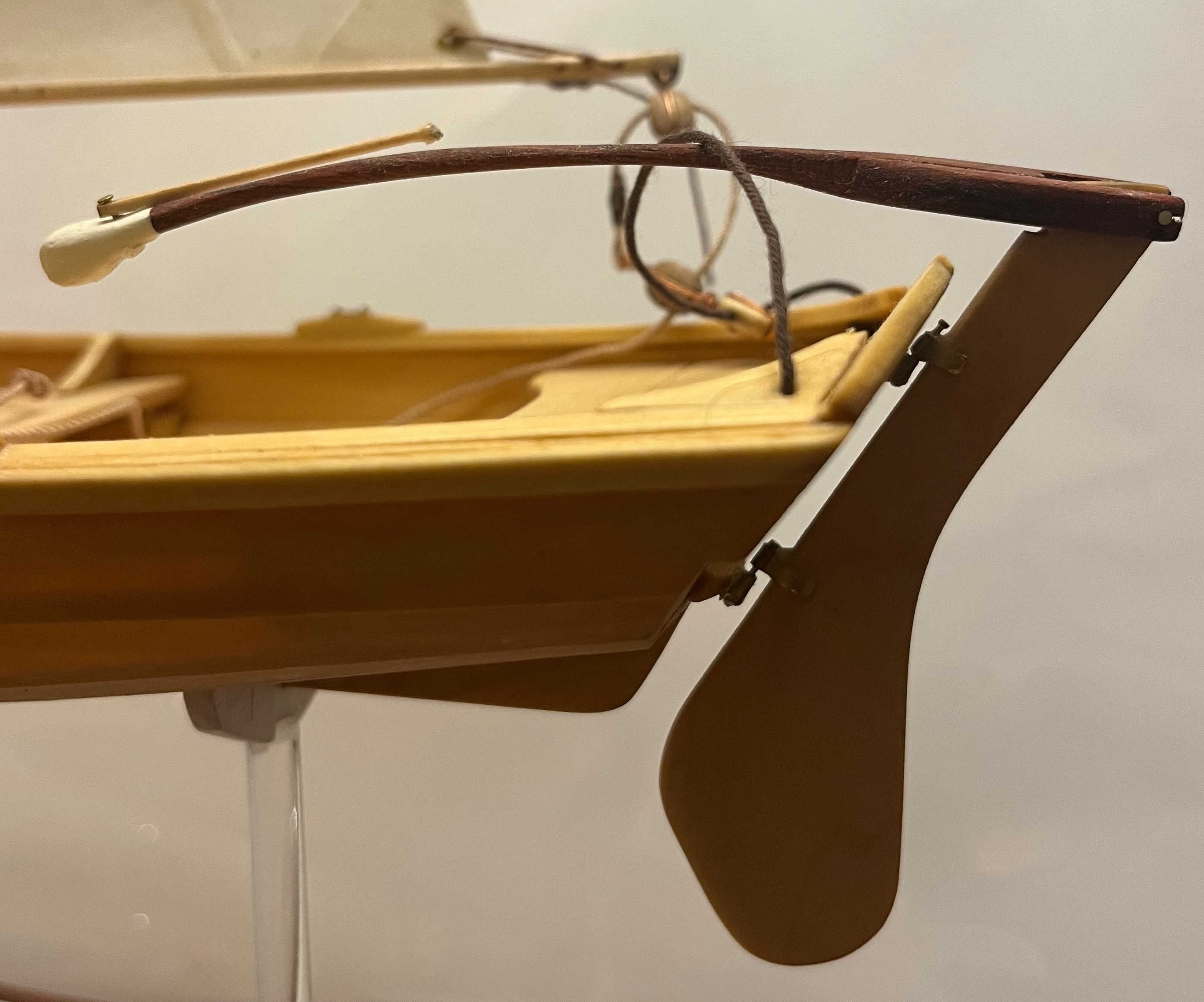
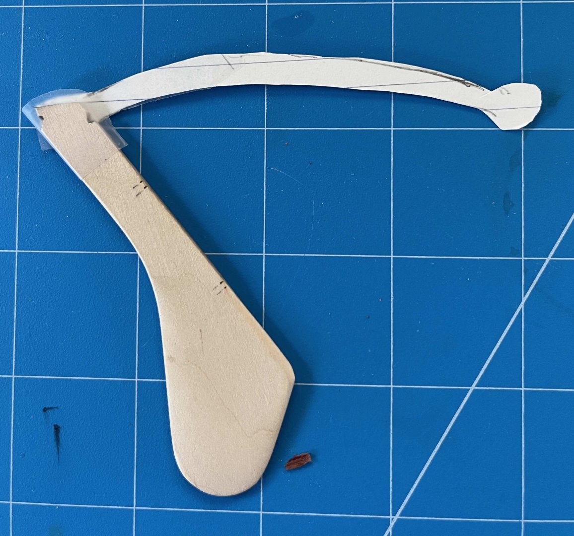
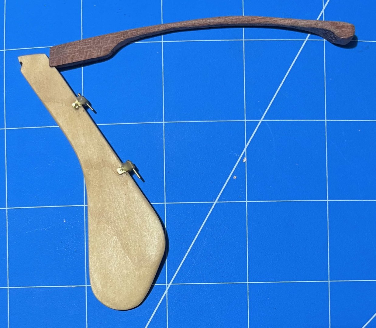
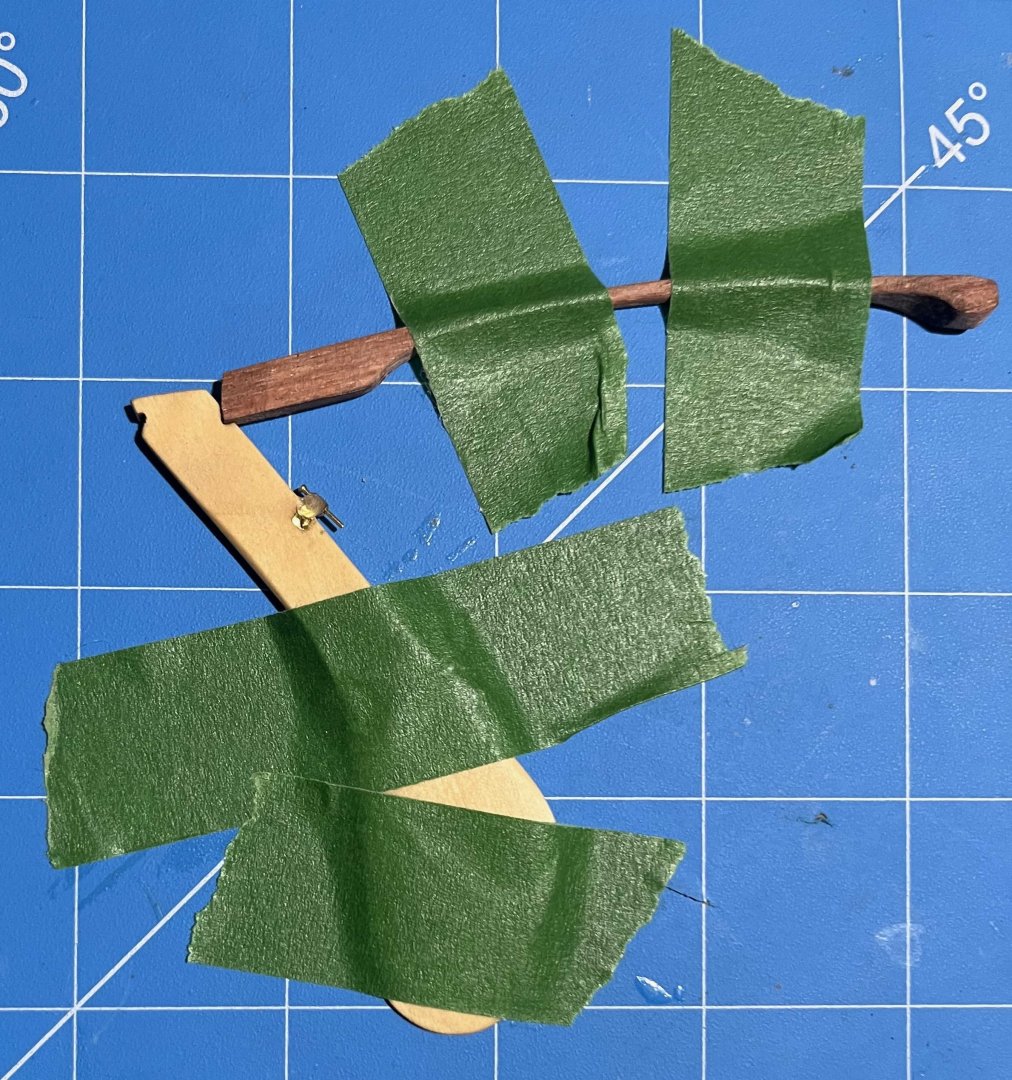
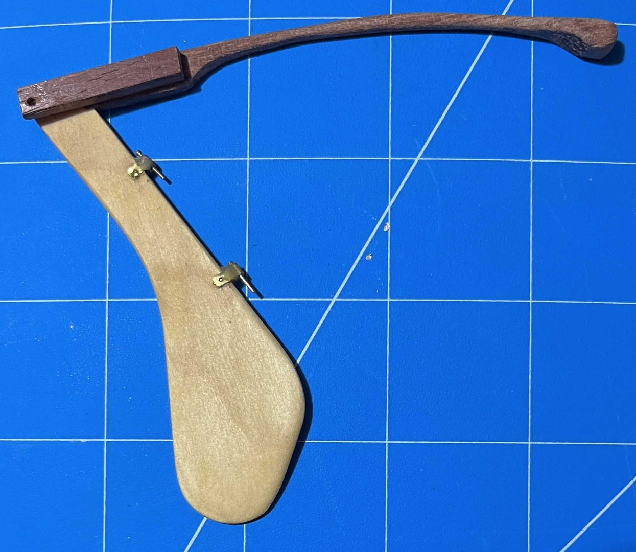
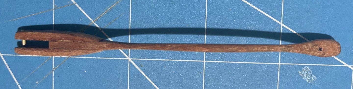
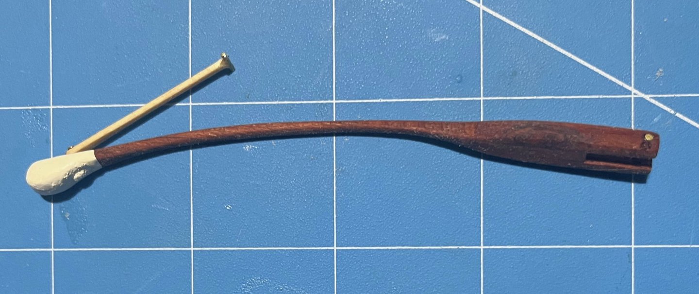
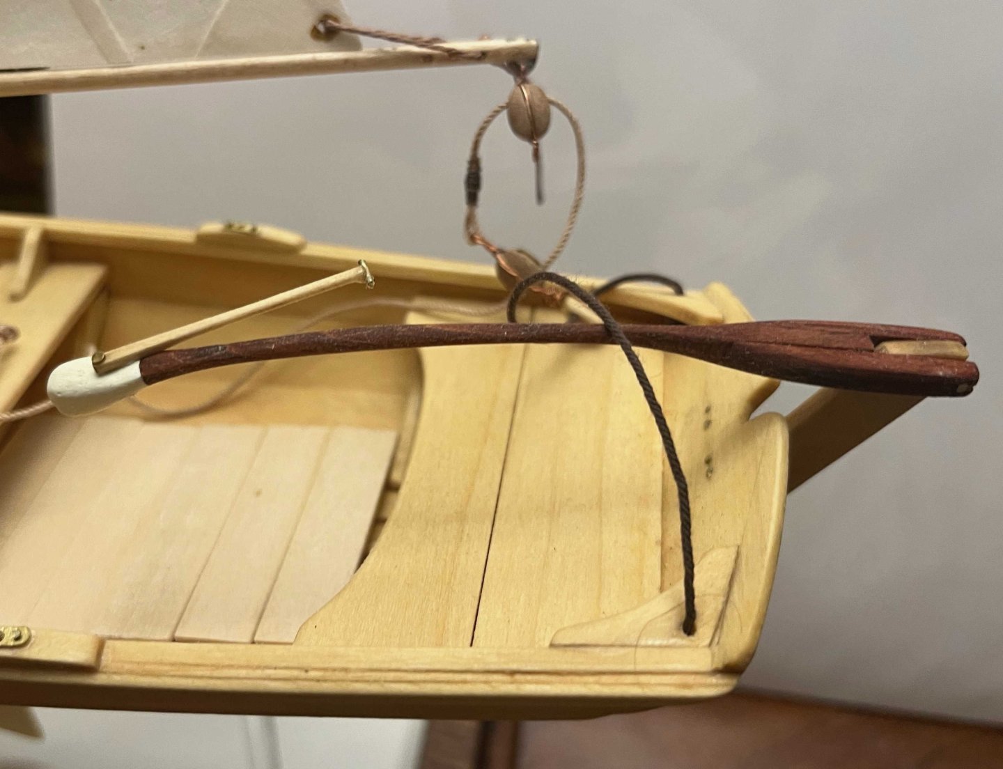
 Tiller finally completed -- only seven months after I started on it! I explained the logic of my chosen solution back on post #89, so no reason to repeat any of that. However, discussion on another MSW thread through the summer got me thinking, so I will state one more point: When building a model of a specific vessel, Nelson's Victory for example, we should really strive to represent that one prototype as she was at some stage in her career. Heading off into fantasies of how she might have been, even though she wasn't, isn't what most of us are about. However, the pram isn't one boat but a design from which many full-size boats have been built. I am not trying to replicate any one of them specifically. Rather, I am aiming for a model of a boat as I would want her if I had one to the pram's design. I haven't tried personalizing the hull but I have modified the rigging, much as I would with a full-size boat. As it happens, my 22fter arrived with a short stick for a tiller, similar to the one in the pram kit. That had met the previous owner's needs but was dangerously inadequate when sailing in the sea breezes in my harbour. I added an extension right away and, as soon as I could, stepped up to the much-more-elegant tiller that the builder offered as an optional extra on new boats: The pram needs a different shape of tiller, to suit her different rudderhead and the angle of her rudder hangings, but I have gone for a similar concept. Since this was a substantial departure from the kit design, I needed to begin with a card template, to check the length and curvature needed, if the end result was to match the ergonomics of a solo pram sailor sitting astride the midships thwart: Then it was time to rough out a scrap of hardwood -- in my case a bit of jatoba, as I have oddments left over from a (full-size) boat project: Back in the spring, I got some way forward with shaping that but the Dremel cut too deeply at one point and I gave up for the summer. Maybe I should have started over but, in recent days, I decided to press on, even though the final tiller would end up thinner than I would have liked (about 1 inch diameter, if scaled up). After a whole lot of hand sanding, I ended up with a near-final shape, matched to the rudder, though with extra wood left at the rudder end as I could not be sure where the side pieces would lie: Also in the spring, I made two side pieces, following the kit's design but longer and in jatoba. I checked the alignment of rudder and tiller on the model (then checked again, and once again). Happy with that and to be sure that everything would line up, I taped the rudder and tiller down: then slipped a brass rod loosely into the hole in one side piece, placed that in the notch in the rudderhead and lined everything up. Oily tropical hardwoods can best be glued as though they were solid plastic -- meaning CA. A dollop of that on the tiller (avoiding the rudder) and the side piece was pressed into place. Once set, the whole thing could be flipped over, taped down again and the second side piece added in the same way. That gave me: Next was a whole lot more sanding, not least to make the top and bottom surfaces of the main tiller and its side pieces flush. Also to smooth the junction between those into a prettier curve. Then I tried putting annealed brass rod through the holes in the side pieces, following the kit instructions. Putting rod into holes was easy but when I tried to make heads out of the stumps of the rod, I just bent the metal and cracked the wood. So I fastened a short bit of rod into place with CA, filed down the metal and sanded the glue off the wood. With a whole lot more sanding, shaping and a hole drilled for the tiller-extension's pivot, I got to: That got its fancy end dipped in white paint and the rest wiped down with tung oil, bringing out the rich colour of the jatoba. Meanwhile,. I took the kit's tiller extension but did not even try inserting the brass crossbar as the instructions want it done. The diameter of the provided rod is very nearly as large as the thickness of the basswood extension, leaving no room for error and very little strength. If the pieces were double their thickness, I would have fitted a wooden crosspiece with a half-lap joint instead, but that was beyond me too. So I gouged a slight groove into the very end of the extension and glued a bit of brass rod there, using CA again. My attempt to form a head on the next piece of rod was as unsuccessful as the previous one had been, so I made the extension pivot from a brass nail, glued into its hole, cut, filed and painted over. That gave me a finished tiller unit that looks like: And in place on the model: Not as neat and nice as I had it in my mind's eye -- but very little turns out that well! Anyway, I'm happy with the final outcome, not least it's colour contrast with the rest of the pram. Now I have oars to finish, running rigging to tidy up and then I think the model will (finally!!!) be finished. Trevor


-
San Francisco cable car by kgstakes - OcCre
kgstakes replied to kgstakes's topic in Non-ship/categorised builds
I personally like the brass look because it draws your eye inside and not towards the railings. Any other votes before it goes to the paint shop?? i couldn’t decide so if no more votes I’ll paint them. I see what you mean and I was think too much paint already but it’ll look good either way. -
 The searchlight towers were added after 1916 and are shown dotted in this Norman Ough drawing which shows an earlier appearance. I believe the dotted lines you mention run to the edge of the platform and just happen to be behind the tip of the spar. I do not know if the cask is really wood; I've only ever seen it in the 3D rendering, which is from the "HMS Lion" entry at navalencyclopedia.com.