James H
-
Posts
5,562 -
Joined
-
Last visited
Content Type
Profiles
Forums
Gallery
Events
Everything posted by James H
-
1:8 1965 Shelby Cobra 427 S/C - Agora Models
James H replied to James H's topic in Non-ship/categorised builds
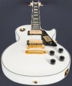
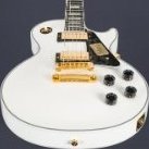
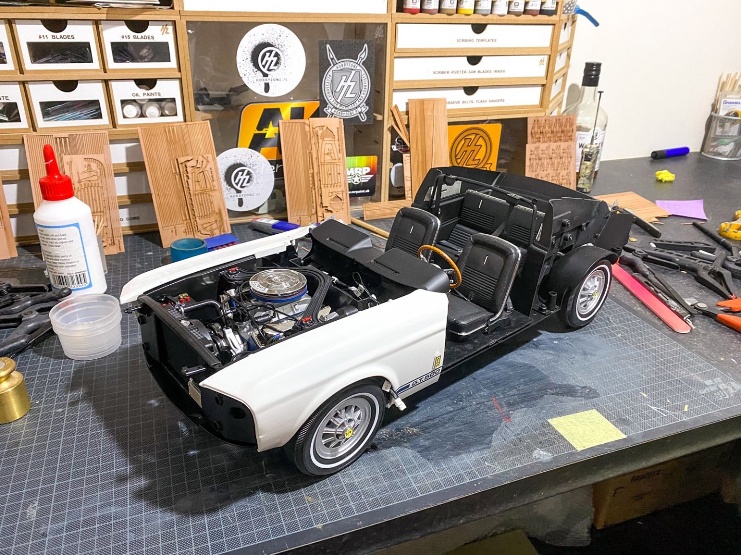
Pretty much. This is the GT500 I'm building. Two more packs and it'll be complete.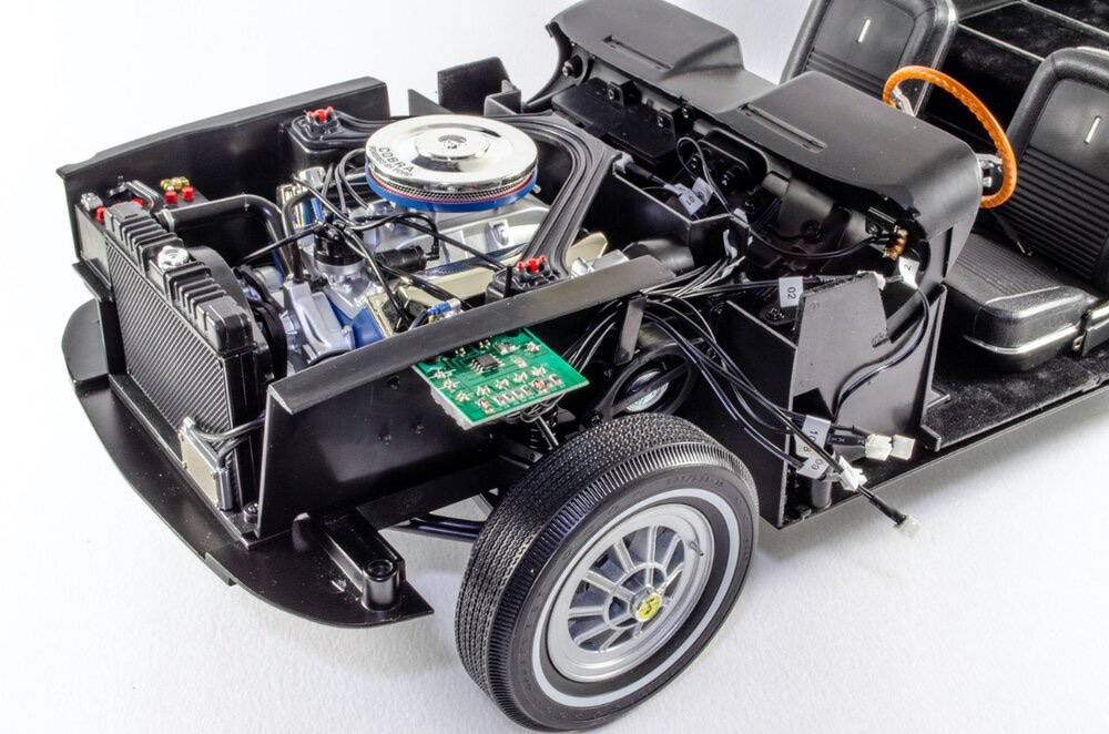
- 63 replies
-
- 14
-

-
1:8 1965 Shelby Cobra 427 S/C - Agora Models
James H replied to James H's topic in Non-ship/categorised builds
Pack 3 This pack now means that we're already a quarter way through this beautiful car model. Even though I absolutely love the Super Snake, I feel this one is even nicer, with its all metal chassis and ingenious assembly. You really do get the feeling that you're actually creating some engineering. Everything fits just perfectly in every way, and she's already gaining some early weight 😆 Ok, let's crack on! STAGE 16: LEFT LATERAL CHASSIS MAIN FRAME BOTTOM SECTION Cross-members 3 & 4 bottom section The left lateral chassis bottom frame is the main player here, and all we need to do is to fasten the two bottom halves of the cross members 3 and 4 to the frame. These are clearly numbered and there's nothing to go wrong here. STAGE 17: RIGHT LATERAL CHASSIS MAIN FRAME BOTTOM SECTION Cross-members 1 & 2 bottom section Now it's the turn of the right lateral chassis bottom frame. The cross members first screw to the left hand frame that I just built, taking care to get the offset holes in No.2 bottom cross member, facing the front of the chassis. With these in place, the new right hand frame section can be screwed to the left hand side, creating a symmetrical unit. STAGE 18: FRONT SUSPENSION SUPPORT: Cross-member No. 4 Top, Left Horn, Right Horn The first part to fit to the lower/bottom frame is the upper part of cross member No.4. The left and right horns now push onto the front suspension support. No glue needed here. This is now put aside until the next stage. STAGE 19: LEFT LATERAL CHASSIS MAIN FRAME TOP SECTION Yet more frame work! The front suspension support from the last stage is now screwed to the lateral left top chassis in this new packet. For this stage, that's it. STAGE 20: RIGHT LATERAL CHASSIS MAIN FRAME TOP SECTION Cross-members 2 & 3 bottom top section Now the right top lateral chassis can be screwed to the previous assembly as shown. You can see just how well everything fits together as the top frame is fastened to the lower frame. Six screws hold these firmly in place. Lastly, the two remaining upper cross member parts (No.1 and 2) are screwed into position. Again, numbers are cast into the parts so you really can't get this wrong. STAGE 21: REAR CHASSIS PART & WISHBONE MOUNTING The rear chassis is first screwed into position... ...followed by the rear suspension wishbone mounting frame. Definitely some weight here now! Remember, this is all metal. STAGE 22: RIGHT FRONT INNER & OUTER WHEEL RIM The front inner and outer rims are screwed together. A very simple stage. STAGE 23: TIRE & OUTER RIM The reverse of this wheel is now screwed into position and the tyre added. To get the tyre on, it really does need to be soaked in freshly boiled water for about 5 minutes to make it pliable. Without that, you will most certainly struggle. ...more next time!- 63 replies
-
- 15
-
-
1:8 1965 Shelby Cobra 427 S/C - Agora Models
James H replied to James H's topic in Non-ship/categorised builds
Pack 2 It doesn't seem two minutes since Pack 1, and this beauty rocked up, so it'd be rude not to crack on and build it. Seems strange to be building the engine on this one so early when it was much later with the Shelby Super Snake. Certainly not complaining as I like the detail stuff. STAGE 07: ASSEMBLING THE ALTERNATOR First, the alternator is assembled and then connected to the mounting arm and mounting plate. These last parts are then swung around, pushed together and then mounted to the oil filter assembly that was built in the last pack. STAGE 08: WATER PUMP PULLEY, CRANK SHAFT PULLEY AND TIMING BELT COVER Work carries on with this part of the engine as the crank shaft and water pump pulleys are screwed together. The timing belt cover is then attached and timing belt added. STAGE 09: LEFT CYLINDER HEAD COVER AND EXHAUST MANIFOLD PIPES This pack only takes a minute or two to complete. All the manifold parts are numbered, as are the ports on the cylinder head cover. They can only fit one way too as they are keyed. STAGE 10: RIGHT CYLINDER HEAD COVER AND EXHAUST MANIFOLD PIPES ...just the same for this pack, and then both cylinder head blocks can be tarted up with stage 11. STAGE 11: ROCKER COVERS, CAPS AND SPARK WIRE HOLDERS Both rocker cover caps are fitted to the rocker covers and these are in turn screwed to the cylinder head blocks. The spark plug wire holders are a little tricky. They kept dropping off my engine, but were later fixed using a knife and a spot of CA. STAGE 12: DISTRIBUTOR, FUEL FILTER, IGNITION COIL AND CYLINDER HEAD CAP The ignition distributor and fuel filter are fastened to the upper engine block with a single screw each. The Cylinder Head Central Cover cap and ignition coil are then friction-fitted to the cylinder blocks. STAGE 13: ENGINE BLOCKS AND COOLING FLUID TANK BRACKET Not a fan of heavy metal, but it's definitely appreciated in a build like this. With these parts, I can start to see how things will finally come together. The right ending block is screwed to the right cylinder head assembly. The same applies to the left hand engine block and cylinder head assembly. STAGE 14: FLYWHEEL COVER, GEARBOX, INSPECTION COVER, GEARBOX RODS Screws are fitted to the reverse of the gearbox inspection hatch. The right flywheel cover is then fitted to the right hand engine block... ...followed by the left hand flywheel cover and right hand side of the gear box. After sliding the inspection hatch into position, the other half of the gearbox is screwed into position. All three gearbox rods are now installed. STAGE 15: OIL PAN, PROTECTIVE PLATE, SPARK PLUGS, SPARK PLUG WIRE AND WIRE CONNECTORS The oil pan is screwed to the protective plate. This model utilises a lot of hidden connections like this where screws are fastened on the inside and the flanged head is trapped between other assemblies. A neat trick to minimise external screw holes. The timing belt assembly is now slotted into position the right hand engine block... ...and the protective plate fitted. The top of the engine is now fitted into position. Both sides of the engine block area finally brought together, trapping the other sub assemblies, and creating a large and heavy engine. Care is needed to attach the spark plugs. A little push and they click into place. There is some wobble in them, but nothing I'm particularly bothered about. And then the ignition lines are fitted. using a colour coded guide (for cutting the vinyl hose) and also for orientation of the leads to the ignition distributor.- 63 replies
-
- 11
-
-
Morning all! Adding to a Shelby I'm currently building, is the beautiful Cobra from Agora Models. I was thrilled with the original Shelby GT500, but I already think this takes it to the next level. I'm also a sucker for the more classic looking car. Agora's new kit comes in their new style box which is designed to withstand the rigours of our postal system, so it arrived with me in great condition. Included with the kit is a large poster, cleaning cloth, and a screwdriver in the first pack of parts. This one is also magnetic, unlike the one in the GT500. Pack 1 Stage 1:Hood/Bonnet assembly As a nice teaser, that very identifiable bonnet is part of the first to item to be built. I still have no idea why some call it a 'hood' 😆 After having experience of one partwork where the bonnet latches were badly moulded and loose plastic bits only, it was reassuring to see that this model from Agora has some proper sprung-loaded latches that also look extremely good. Yes, a little fiddly to assemble, but definitely a nice touch. Some neoprene tape is also added to the top edge of the bonnet to protect the bodywork from being marked. Stage 2: Left-leaning Front Wheel Unlike Agora's GT500, we get an early appearance from one of the wheels. With this one, the centre wheel section is sandwiched between the outer rims, as well as being firmly screwed into place. It's also vital that you soak the tyre in just-boiled water for around 5 minutes to soften it enough so you can fit the inner assembly in position. This one still took a little wresting but it does fit in the end. Now the wheel brake is assembled as shown, and a single screw holds the parts together. The brake assembly will only fit into the wheel in one position due to a slot system, and the wheel is secured from the outside using a screw. Be careful not to tighten too much or the wheel won't rotate. The hubcap is then pushed into the knock-on and this fasten my magic magnet to the wheel. Stage 3: Steering wheel and exhaust parts I'm not sure what the leather seat is made from, but it does feel like leather and is beautifully soft. The steering wheel also has a realistic wood grain effect. The Cobra badge fits to the middle and will only fit the correct way around as the locating pips are different sizes. The exhausts are also a much fit and can only fit one way round. Stage 4: Engine & Exhaust Parts Perhaps the most fiddly part of this is curving the photo-etch edge of the air filter. To help, I first wrapped it around a small paint bottle and then inserted in the groove in the air filter top. This is all locked in place when the bottom is added. The carburettor bottom and top are now added and the whole assembly fitted to the engine block. The exhaust manifold parts are numbered and plug into the main exhaust system. I found things fit a little easier by scraping away some of th chrome plating first. No glue was needed at all as everything was a very good fit. Stage 5: Oil Filter and Exhaust Parts The oil filter is fitted to the bracket which then connects to the engine plate. There's not a lot to this pack as the exhaust parts are scheduled to be completed in the next stage. Stage 6: Exhaust Pipes As with the first exhaust, the manifolds on this are assembled in the same way as the first, using the numbering system. This is a little fiddly but goes together quite well. Final adjustments can be made later in the build. That's it until next time 😊
- 63 replies
-
- 10
-
-
Please do! Another sure will be good 😎
- 382 replies
-
- 3
-
-
- Vanguard Models
- Duchess of Kingston
- (and 1 more)
-
That is looking so nice. Glad the Chaos Black fitted the bill too.
- 222 replies
-
- 4
-
-
- First Build
- Lady Isabella
- (and 2 more)
-
That really is very beautiful. Is that boxwood or lemon?
- 67 replies
-
- 1
-
-
- granado
- cross-section
- (and 1 more)
-
That sir, is looking champion! The sanding and shaping look real good. The second layer should be quite easy now.
- 382 replies
-
- 2
-
-

-
- Vanguard Models
- Duchess of Kingston
- (and 1 more)
-
I'm interested too. Minwax Wass recommended to me, but not sure it was water-based.
- 222 replies
-
- 1
-
-
- First Build
- Lady Isabella
- (and 2 more)
-
Excellent work! I'd love to see you start your own build log and sharing with us please. Nicely planked hull.
- 382 replies
-
- 4
-
-
- Vanguard Models
- Duchess of Kingston
- (and 1 more)
-
That's looking spot on. Those ply bulwarks are easy enough too. You shouldn't have any ripple with them on the bow either. Just get the top of them as close to the tops of the bulkheads as you can.
-
Pretty much anything is fixable, especially at this stage. Just take your time. Really liking watching you build this one.
-
Looking nice! Any chance you can still twist those stern planks in a little so they make more contact with the false keel?
-
Thanks for that. I'll keep this link here, but please can this topic be limited to the software that Rob has posted here. That will keep this topic straightforward.
-
Pinned! (...and thanks for all your work, Rob)
-
Looking real good. It's good to get that first planking on and them remove those temporary beams.
- 382 replies
-
- 2
-
-
-
- Vanguard Models
- Duchess of Kingston
- (and 1 more)
-
Ship's launch kits for 18th century ships - 1/60 or 1/64
James H replied to peterbrowne's topic in Wood ship model kits
There will be a 1:64 range available from Vanguard Models in the near future. I'm building the prototypes very shortly. -
New 1:48 HMS Endeavour out later this year
James H replied to James H's topic in Wood ship model kits
'Loosely' admiralty style, I reckon. Looks very simplistic. -
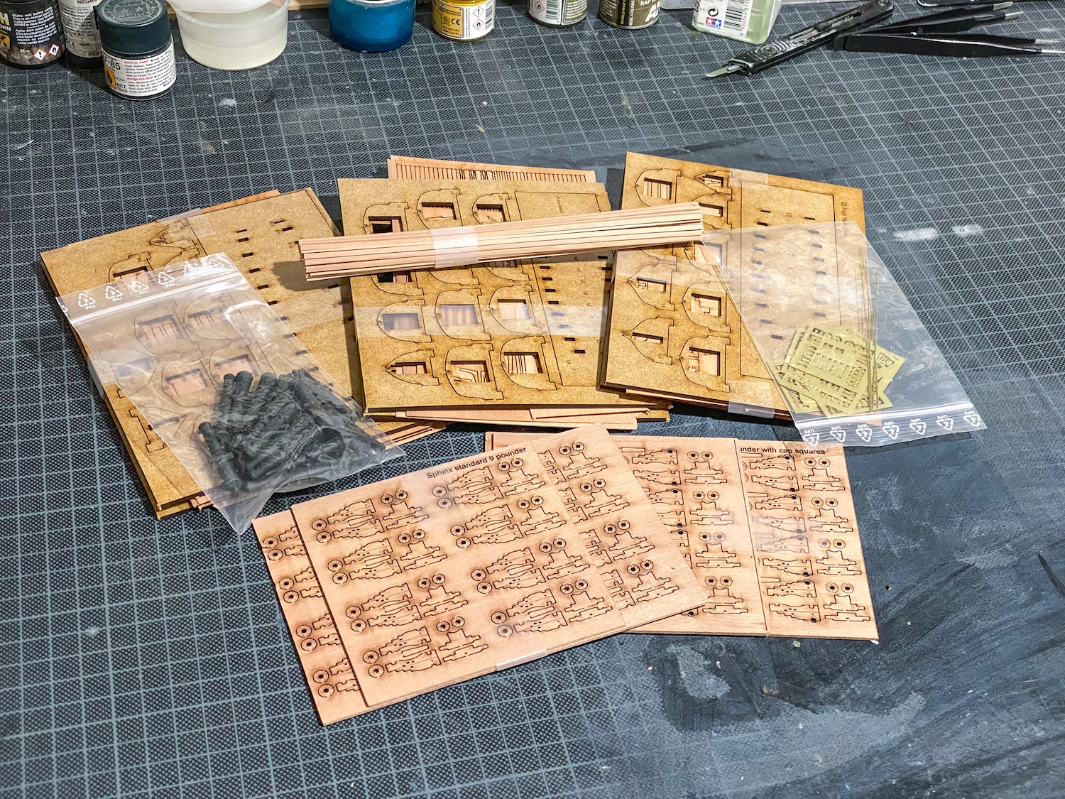
Nice to see another Duchess coming together. You can tell it's a very solid frame! Yes, there are so many interlocking slots that applying glue afterwards is the safest way and PVA/Titebond have good penetration...and even more so with a little dilution too. I've had to use this method on Victory too because of the sheer size of joint coverage area. By the time I'd be half way through applying, the chances are the glue would be going off, so application afterwards was key.
-
Thankfully, there's zero reason to do it except for aesthetics for visible edges. Chris Watton did a test on this theory a long time ago and there was no weakness in a joint still carrying char.
- 382 replies
-
- 2
-
-
-
- Vanguard Models
- Duchess of Kingston
- (and 1 more)
-
You'll have to ask Chris that. I just have to build these up.
-
Fresh from Vanguard Models. A 'sign' of things coming... 🤫😆
-
I get moments like that too and I'm 50! Carry on! 🤣
- 382 replies
-
- 2
-
-

-
- Vanguard Models
- Duchess of Kingston
- (and 1 more)
-
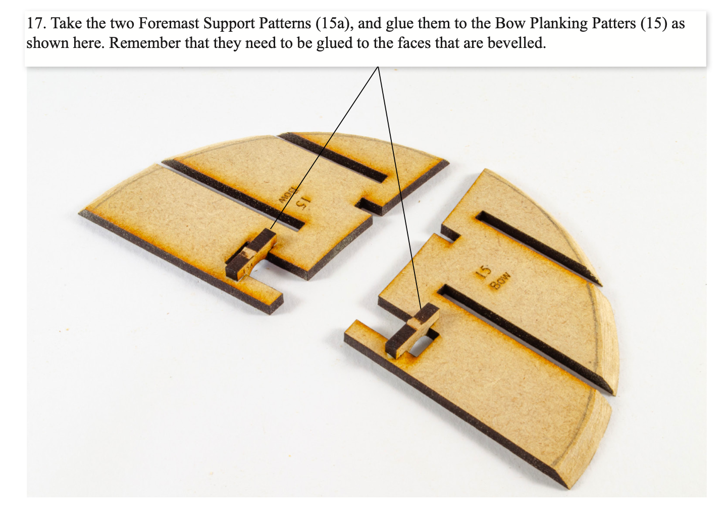
I don't want to hijack this log at all, but this is in the manual I wrote:
- 382 replies
-
- 2
-
-
- Vanguard Models
- Duchess of Kingston
- (and 1 more)