thibaultron
-
Posts
2,951 -
Joined
-
Last visited
Content Type
Profiles
Forums
Gallery
Events
Everything posted by thibaultron
-

Fokker Dr.I by Torbogdan - FINISHED - Model Airways
thibaultron replied to Torbogdan's topic in Non-ship/categorised builds
For the less machine tool gifted, how about stacked disks, alternating large and small dia.? -
I think the "temp" label refers to the bolt pointed to by the arrow. The outer timbers may be free floating, and serve only to tie the side and transom planking together at the corner.
-
April 10, 1963 - USS Thresher tragedy
thibaultron replied to torpedochief's topic in Nautical/Naval History
May they rest in peace!! -
The frames were out by 1/16", or 2" in real life. I don't doubt that this may not have been true on the real boat, and probably fixed in much the same way. Years ago while living in MD. I read an article on a local large wooden boat builder, one of the last in the area. He said that all the boats he built, and all of the ones he knew about were asymetriacal by a fair amount, that modern ship builders would be surprised by. The nature of wood construction.
-
Looks like a good book, ordered one. Thanks!
-
Need tips on deadeyes rigging
thibaultron replied to Tallsails2's topic in Masting, rigging and sails
In model railroading we have a saying. "There is a prototype for everything!" We also have a saying, "Never put a window in a chimney!" A couple weeks ago I posted this picture, on my Railroad Forum: When I was a teenager, I passed this house everyday going to school, and just looked it back up on GOOGLE Maps. Having said that, you also have to consider your viewer. Sometimes making a model realistic, can also make it look odd, or unfinished. In the end, however, it is up to you, what you want in your model.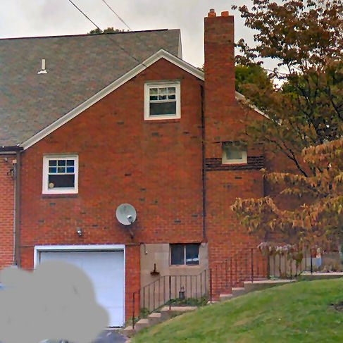
-
BTW. I have the HMS Alert kit from the same manuf. The smaller 1/96th scale, non laser kit.
-
The only thing about the kit, is I would reca0end not applying the copper tape. A US/Colonial ship of that period, was unlikely to be coppered. The British were just starting to copper their warships about this time (1780). Coppering was very expensive, and experimental at this stage. A private builder was unlikely to be using it. I will be following this build. I love the Baltimore Clipper type ships!
-
RIGGING THE ROYAL WILLIAM
thibaultron replied to piratepete007's topic in Masting, rigging and sails
It will likely be Mon. before I can start. Have to work the next 3 days. -
RIGGING THE ROYAL WILLIAM
thibaultron replied to piratepete007's topic in Masting, rigging and sails
I'll read through the whole thing in the next few days. -
RIGGING THE ROYAL WILLIAM
thibaultron replied to piratepete007's topic in Masting, rigging and sails
What a wonderful resource! Thanks for your effort! -
Fokker Dr.I by Torbogdan - FINISHED - Model Airways
thibaultron replied to Torbogdan's topic in Non-ship/categorised builds
My thoughts on the paint/no paint options. If you were building a plastic model of, say a model "T", or a ship, would you leave it the raw plastic color, or would you paint it? I would leave the wood parts with a clear coat, and paint the other parts the correct historical colors. -
They make stuff you can brush on rotten wood trim to harden it. Then you use filler to restore the surface. This has fungicide in it. It is thin and soaks into the wood. Maybe these compounds would work. I think one brand was Dr. Wood.
-
For the problem that the surface in contact with the balloon/bag is smooth, perhaps cover the "mold" with similar cloth, apply the paint/epoxy, etc., let it set then spray it with some sort of mold release. After that put the real sail on. that way the mold surface would be textured, not smooth, and both sides of the sail would be textured.
-
My Spray Booth Construction
thibaultron replied to thibaultron's topic in Modeling tools and Workshop Equipment
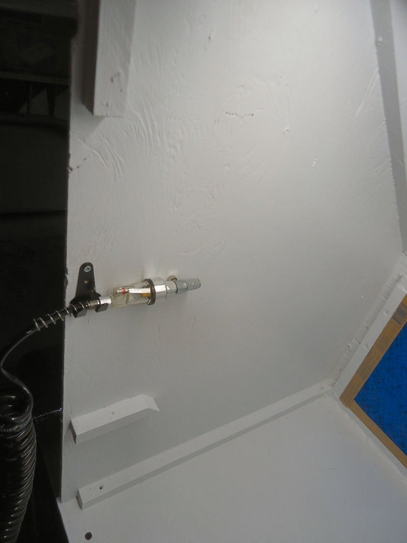
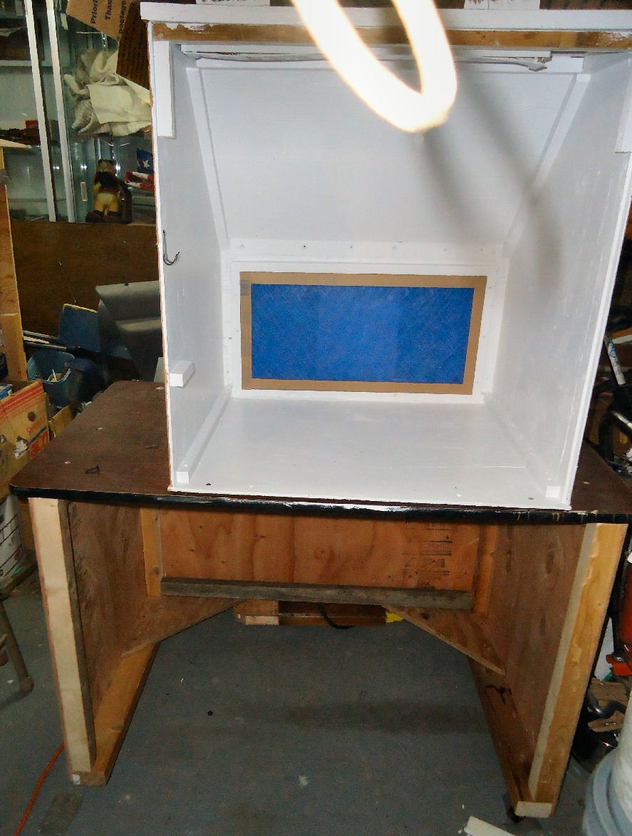
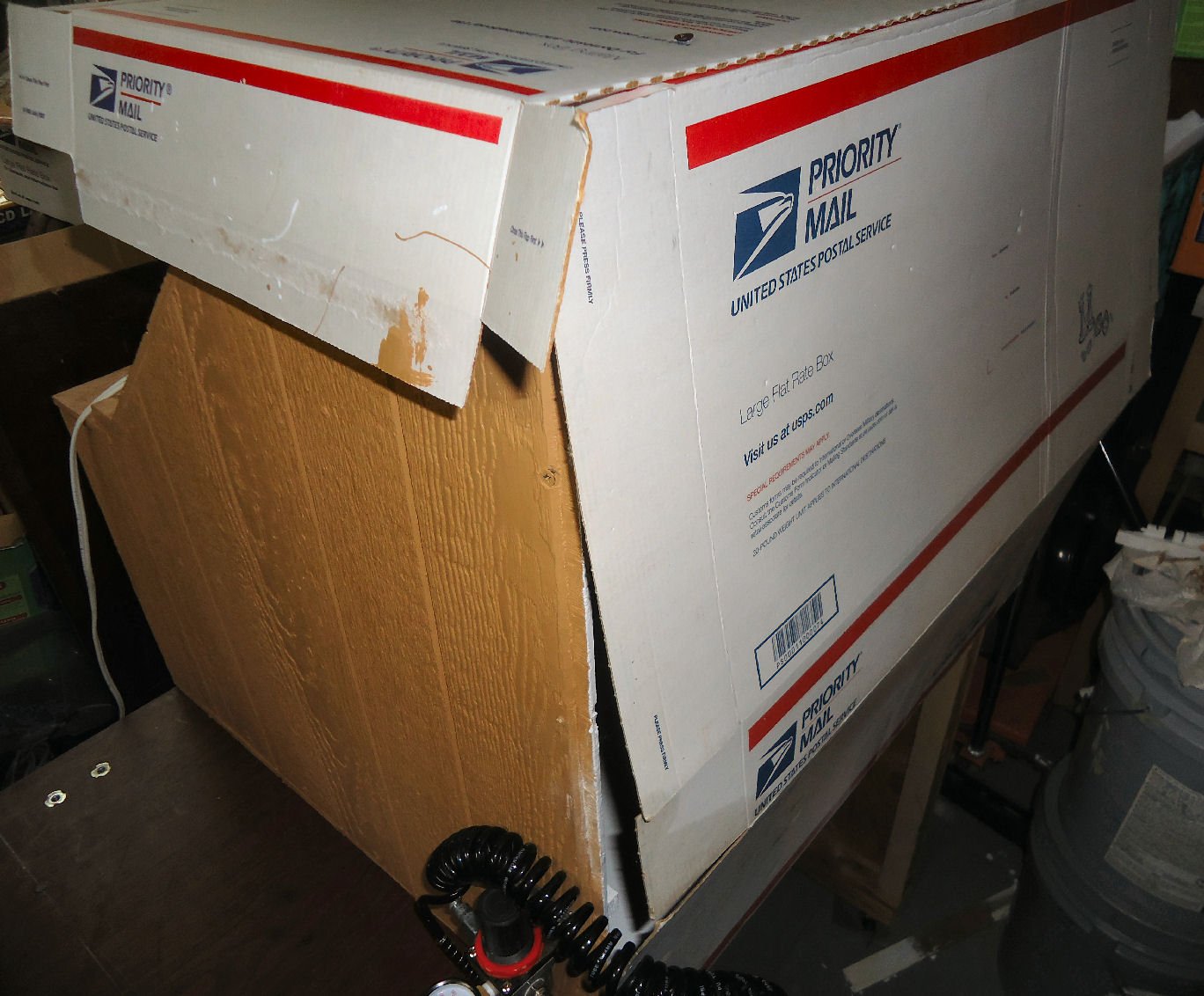
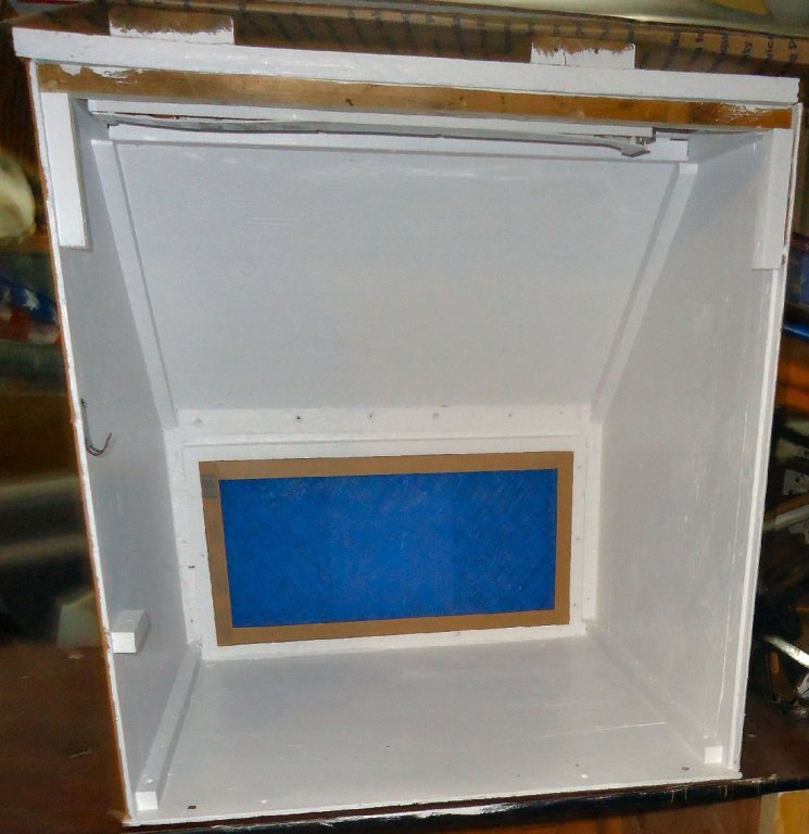
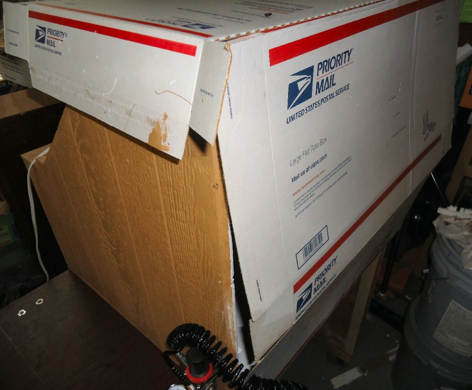
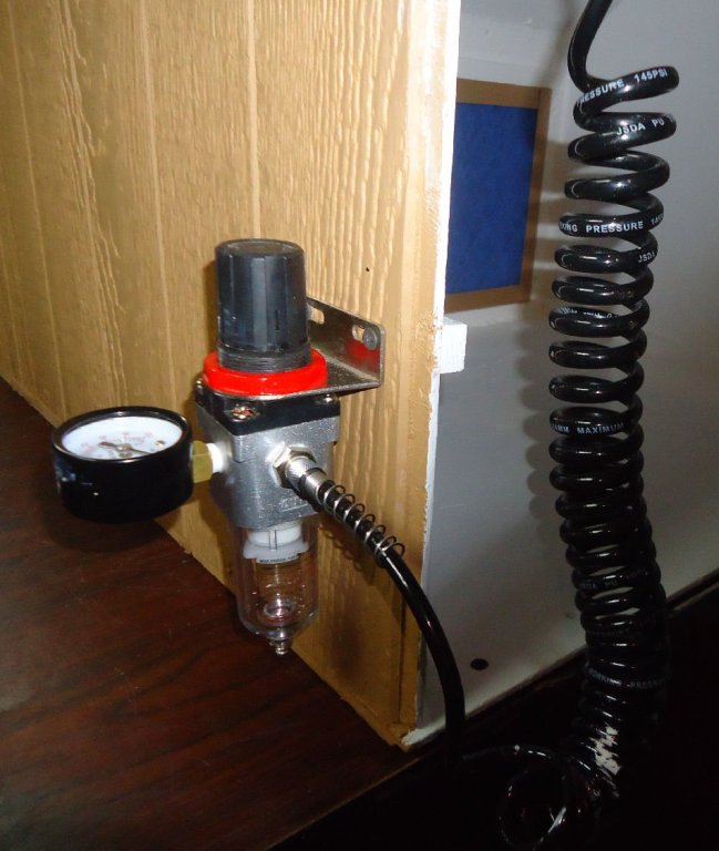
Here are some pictures of the finished spray booth: These are a couple of pictures of the airbrush mount, and the regulator mount. The short length of glue strip is there as the regulator mount screws were longer than the ply was thick. I made a temporary dust cover for the booth out of a couple boxes, that I used as drop “cloths” while painting the booth.

-
A method for making panelled sails using paper
thibaultron replied to Cathead's topic in Masting, rigging and sails
Thanks for this tutorial! I think I'll use this method for my 1/64th Skipjack, that I may even have time to get back to soon.- 49 replies
-
- 7
-

-
- sails
- sail panels
- (and 1 more)
-
Could the sound have been lessened by the blast being outside the hull?
-
If you go directly to Google Translate https://translate.google.com/?sl=la You can type or paste in the web address, and it will translate the entire page.
-
My Spray Booth Construction
thibaultron replied to thibaultron's topic in Modeling tools and Workshop Equipment
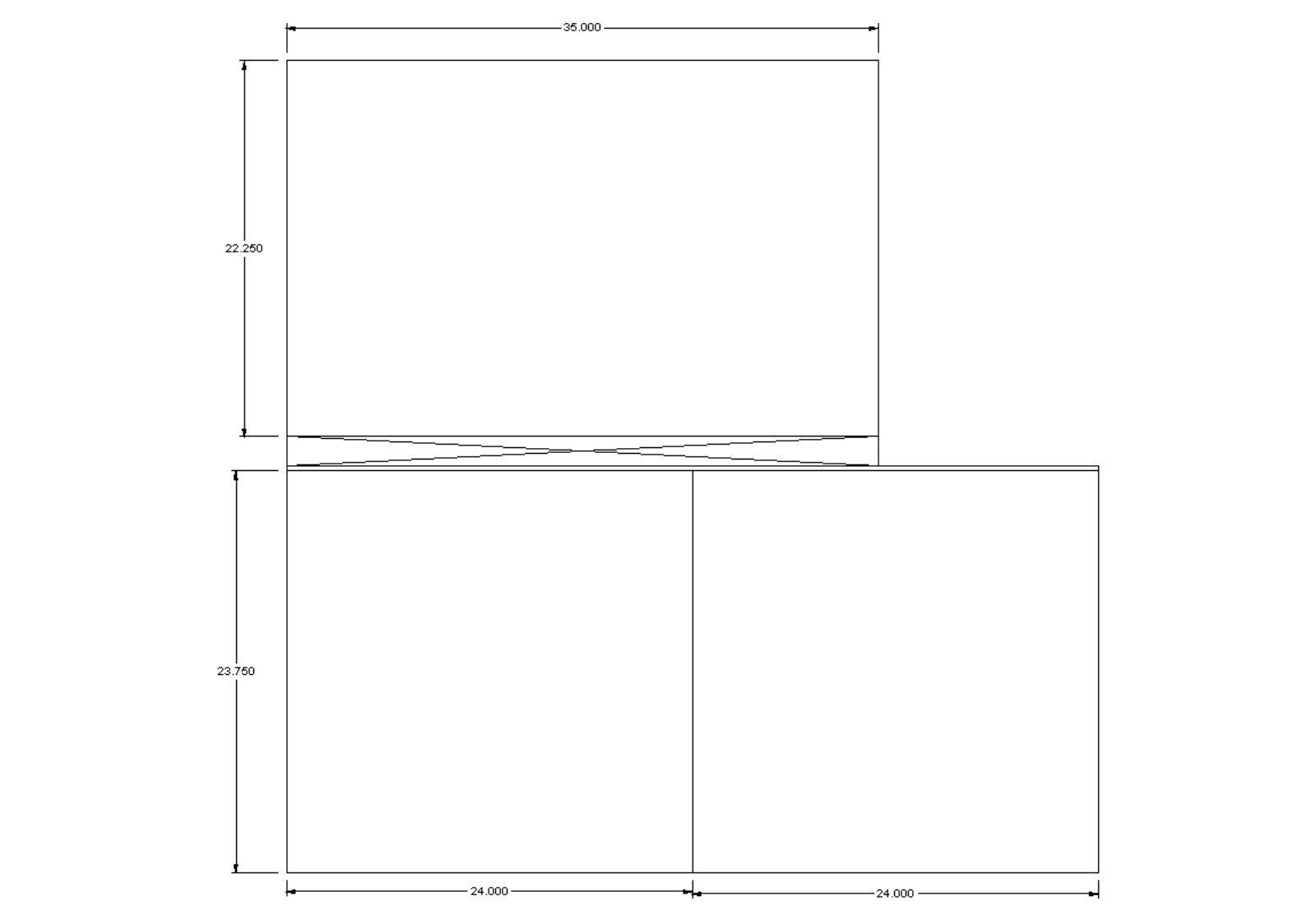
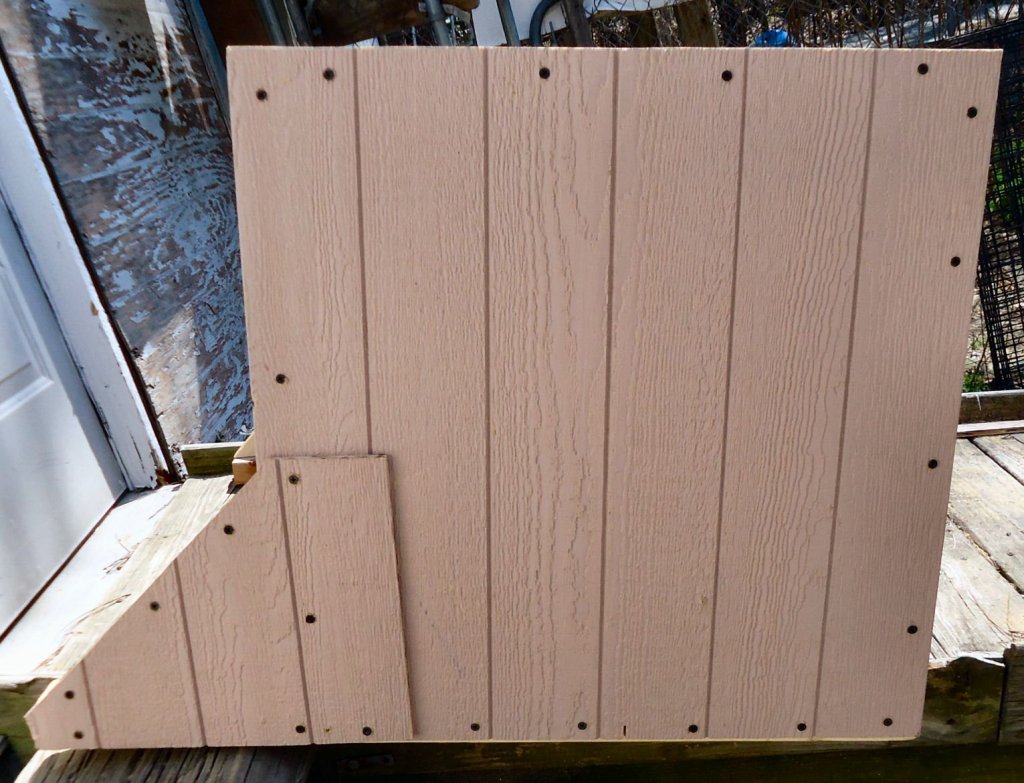
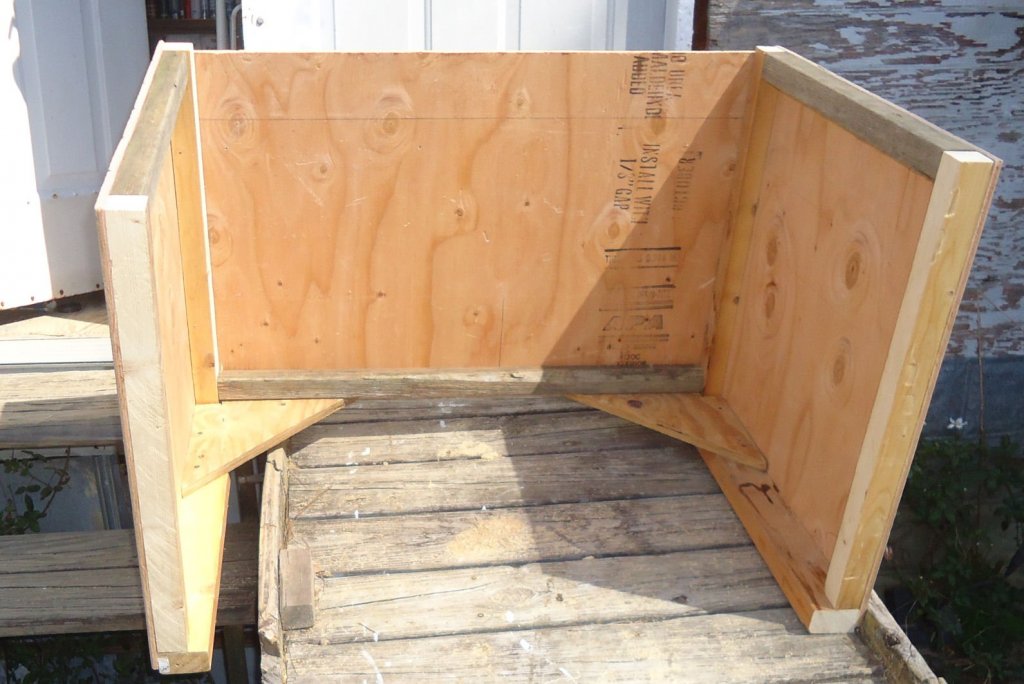
Booth Table I built the base for the table today. I didn’t attach the table to it. I want to attach the casters first, and I haven’t bought them, yet. I designed it for the larger 3’ wide booth, just in case. The wider booth is 28” deep plus 5” for the blower. So, I made the base 33” deep, so that the whole assembly would not be back heavy, with the blower hanging in mid air. The smaller booth comes to 29” deep. Maybe later, I’ll cut the base down, if I stick with the smaller booth. Here are a couple pictures of the drawing. The first is the lumber frame, without the casters. The table top is only 24” deep, therefore I made the main section of the base this deep. Happily, there was just enough of the 3/8” plywood sheet left to skin the back and sides. The bottom of the base extends past the main section to give me the 33” deep footprint I wanted. The width of the base was determined by the 35” width of the top of the remaining plywood. In my normal frugal mode, I found a 74” long piece of 2 X 6 and a length of 2 x 4, that I ripped down to make the frame pieces. Note that the 2 X 4 also supplied the second piece “E”. Here are the cuts for the plywood. This is the resulting assembly. I ran out of long screws, and reused the pieces cut from the booth sides to attach the “E” parts. The angle was not quite the same, but it doesn’t look too bad. I used a couple of pieces of ¾” plywood to reinforce the back corners. These were recycled from an earlier project. Waste not, want not.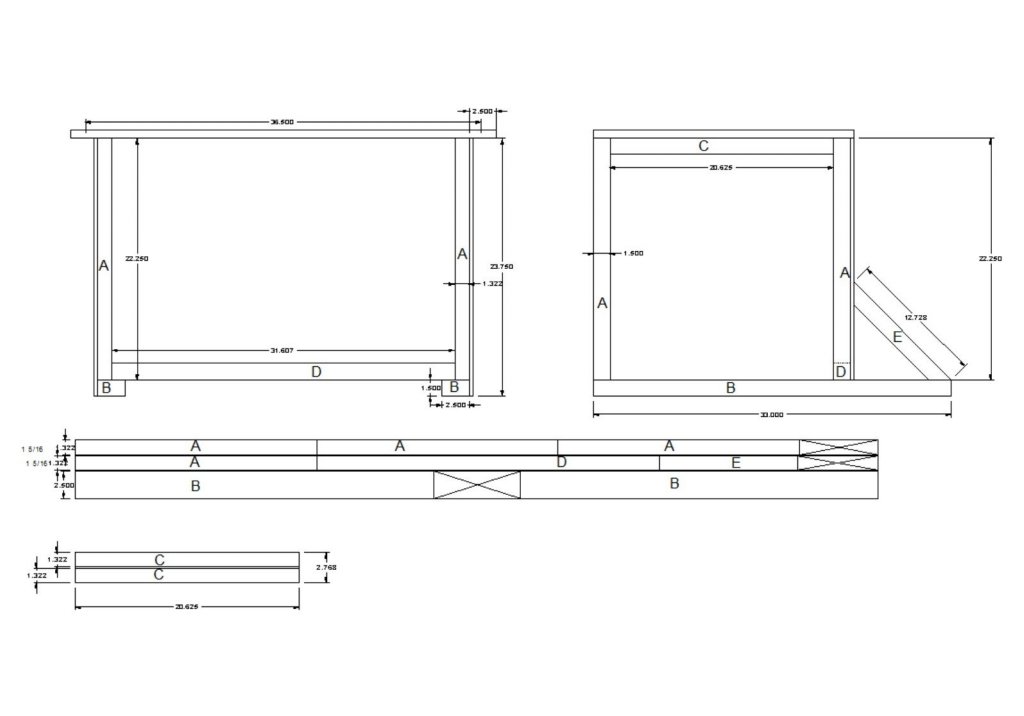

-
Of course, if you don't have the sails fully set, people are going to continuously ask why. :-)