thibaultron
-
Posts
2,944 -
Joined
-
Last visited
Content Type
Profiles
Forums
Gallery
Events
Everything posted by thibaultron
-
I watched a show many years ago on Queen Elizabeth I. In it they mentioned that ALL portraits or paintings of her commissioned or otherwise had to follow very strict rules. There was a pattern that was distributed for her face that was a sheet of paper, with many small holes. The artist place this on the canvas and used powder to mark the hole pattern. Then he had to paint "within the lines". I assume that the body proportions had to match the face. Any painting found that did not meet the standards, or paint her beautiful, was subject to harsh punishment! The painting AND the artist's studio would be burnt! I forget what additional punishment the artist himself received. So basically we know nothing about how she really looked, at least later in life.
- 5 replies
-
- 2
-

-
- cloudesley shovell
- longitude
- (and 4 more)
-
As far as frapping the gun lines. Remember, it could be hours between sighting an enemy ship, and actually engaging her, so plenty of time to get ready.
-
 What a great family historical project! And the quality of your Uncle's work at that age!
- 53 replies
-
- 2
-
-
- clipper
- restoration
- (and 1 more)
-
Western equivalent, HMS Furious Battlecruiser partially converted to carrier, then later to a full carrier. She was a weird duck too. Started out with two 18" guns one each in two turrets, one fore and one aft. Later fore turret removed, and flat top added forward. The Pilots had to manouver around the super structure to land. Later aft turret removed and aft flight deck added, but too much turbulance from super structure. Then cut down and made full carrier.
-
On Ebay, you can set a Reserve Price, and the item will not sell if it is not met, then you can try additional times.
-
Well, here is another way the Kathryn differs from other Skipjacks, Her bowsprit is straight! In every other Skipjack I've ever seen, the bowsprit curves down at the forward end. I wonder if that is a feature of her rebuild. Yes, straight is what the HERR plans show.
-
Sail design for 18th-century longboat?
thibaultron replied to Cathead's topic in Masting, rigging and sails
Recently a study of the pyramids using some type (I forget the tech name), of deep scanning equipment, they found that there appears to be a ramp spiraling around the outside of the structure, just under the present surfaces. So they used the ramps for most of the construction, then covered them over when they finished the outside. At least that is the latest theory. -
I once read an article in a modeling magazine, about a highly detailed scratch built WWII Germany armor/gun. The author said that in building the vehicle, he had probably thrown away an entire other model in incorrectly made parts. So you are doing great to only have to make the corrections you have.
-
Fokker Dr.I by Torbogdan - FINISHED - Model Airways
thibaultron replied to Torbogdan's topic in Non-ship/categorised builds
My wife used to write poetry to a service that hosted it free. Then one day, it was all gone! Got a message from the service that basicaly stated, "If you would like a copy of your files, send money." Worse even them your experience with Photo Bucket, at least you can still see them. As I remember the fee was fairly large too, didn't mater, we didn't have the money then. -
Sail design for 18th-century longboat?
thibaultron replied to Cathead's topic in Masting, rigging and sails
Chuck; How is the traveler block attached to the contemporary models? Is it possible that the lower block was not permanently attached, and only installed when the sails were in use. If so, maybe the attachment was easily released, and the block could be swapped side to side quickly. -
What is the name of the MRH painting article?
-
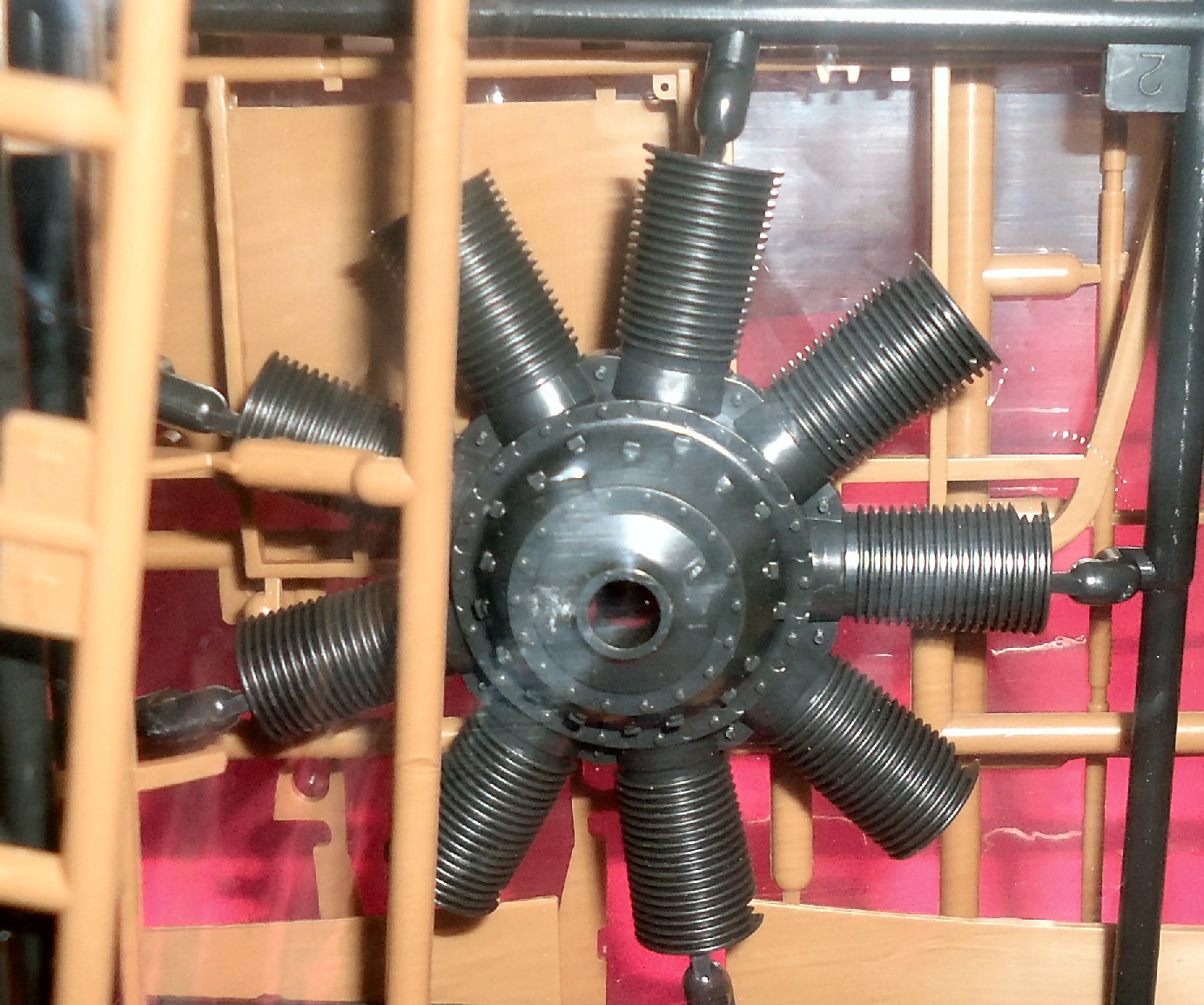
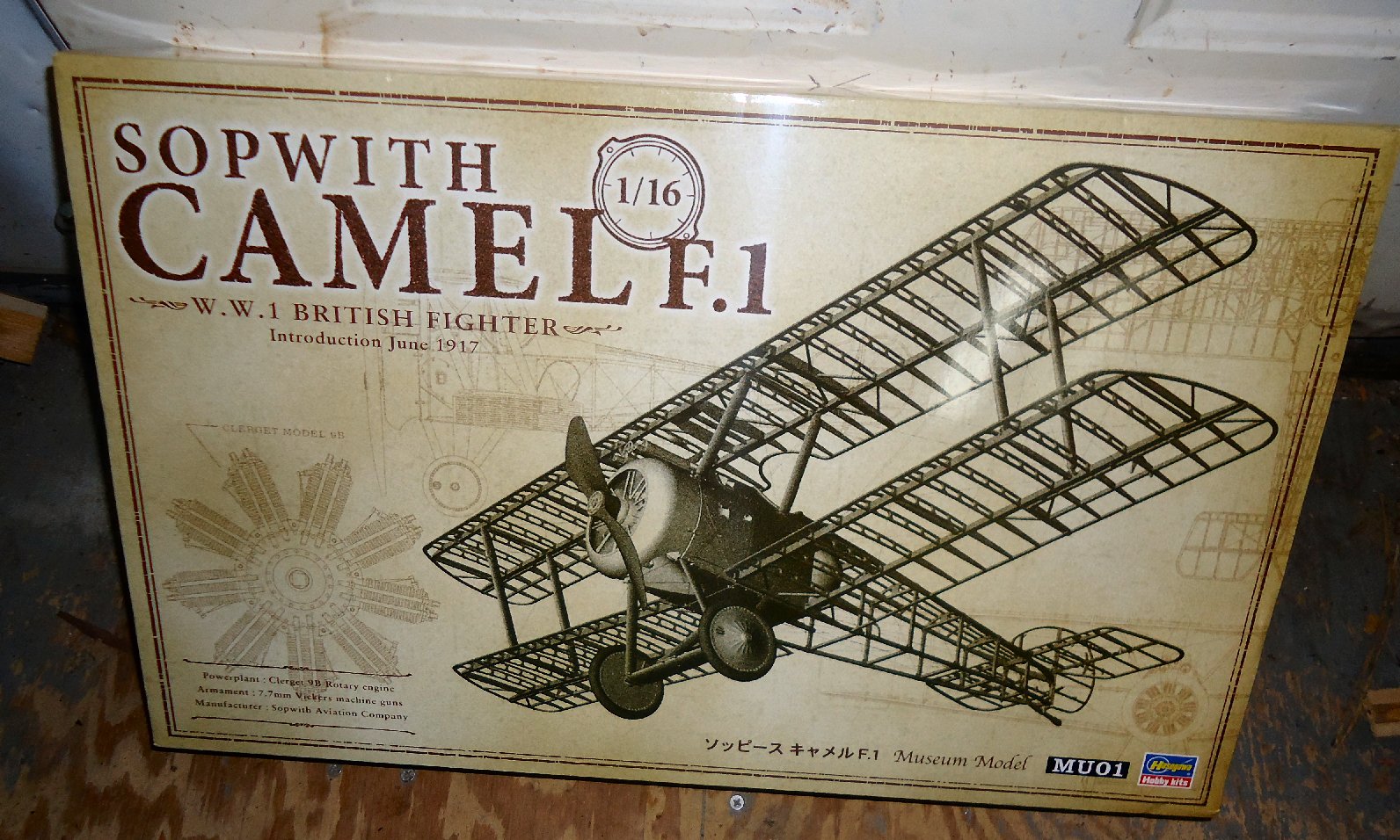
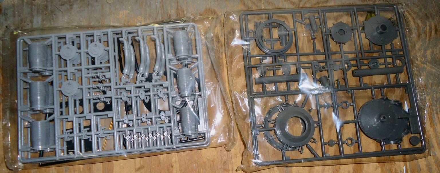
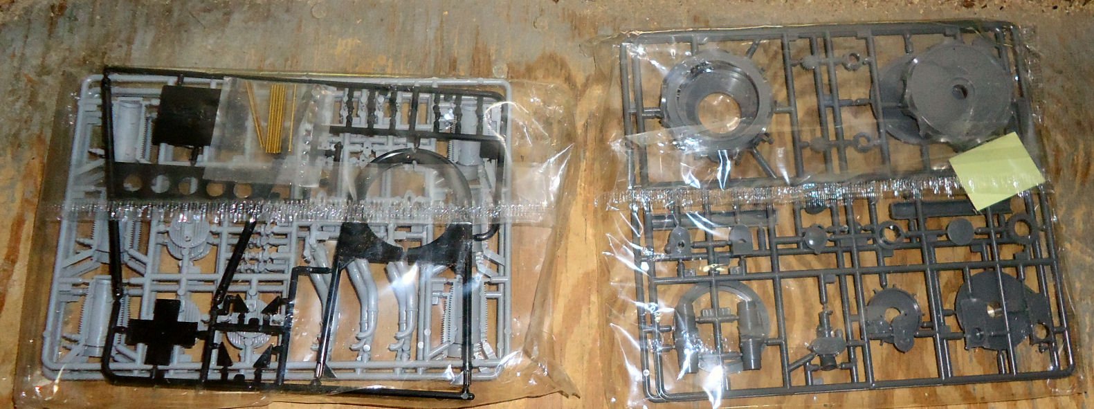
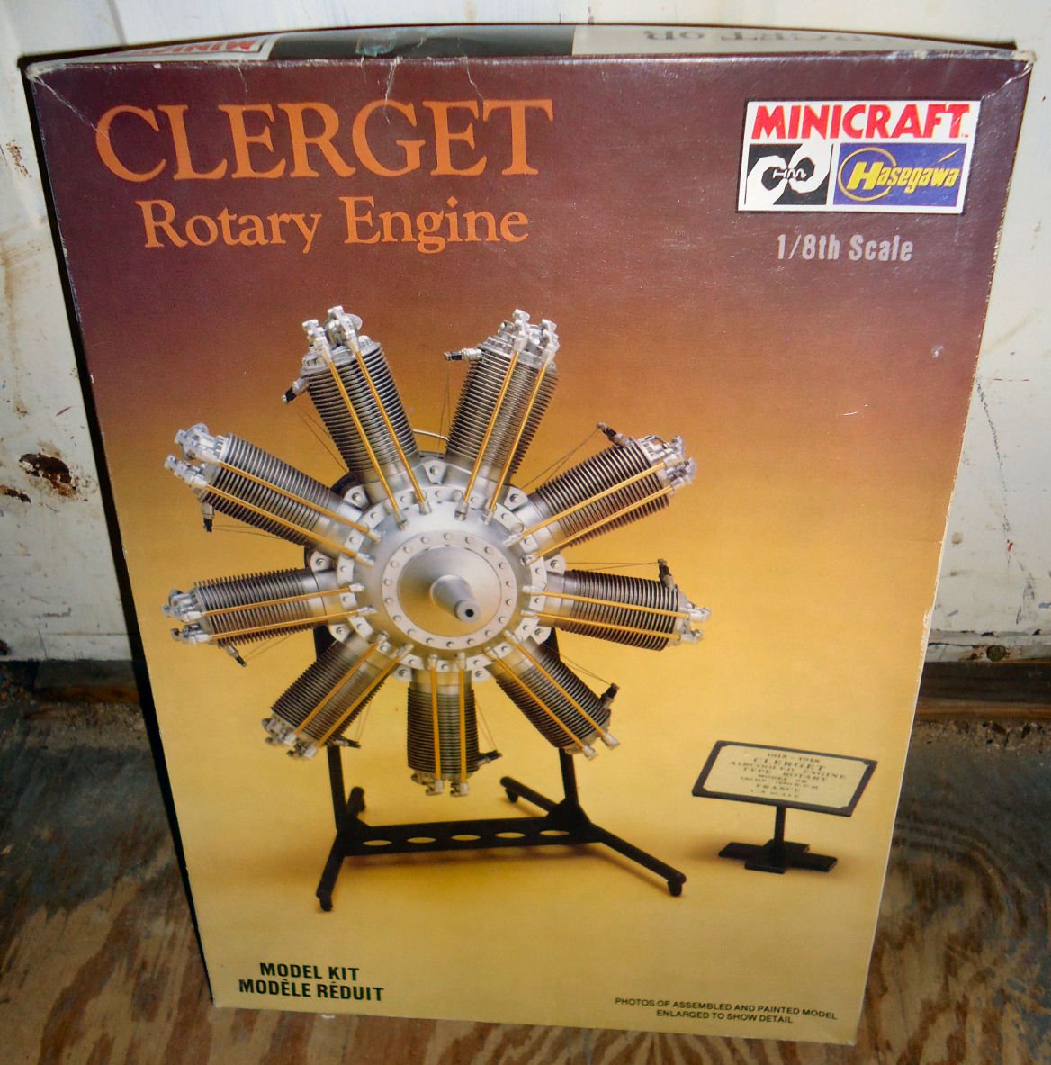
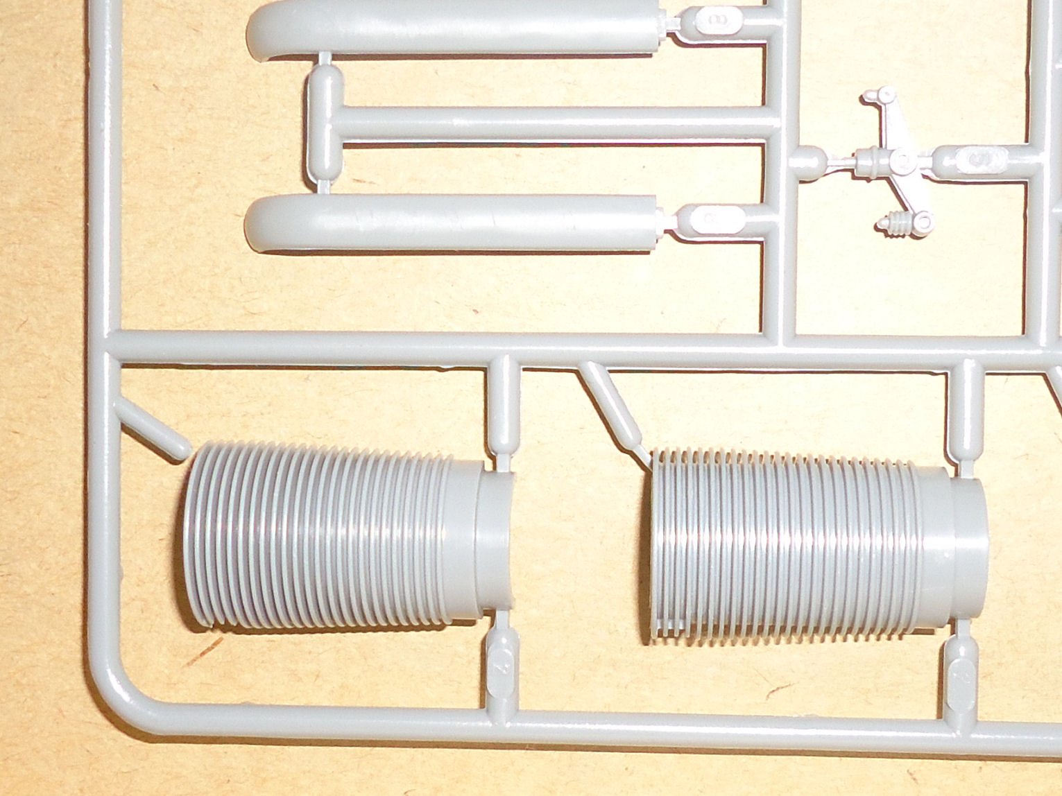
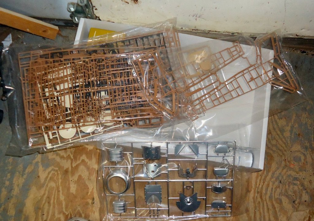
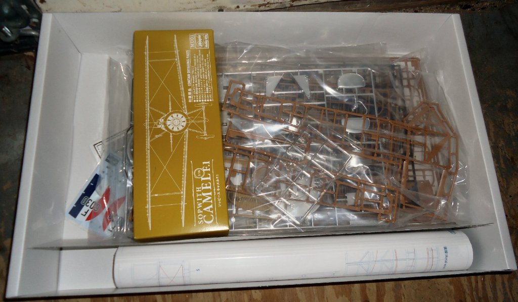
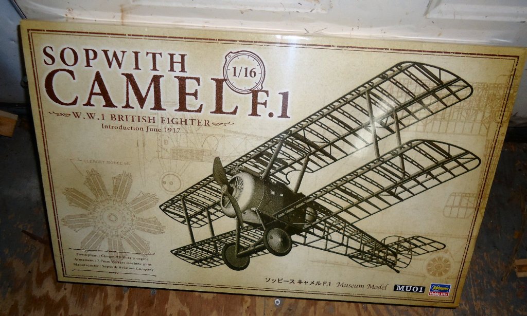
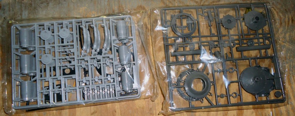
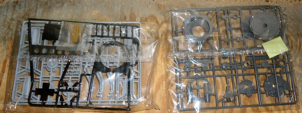
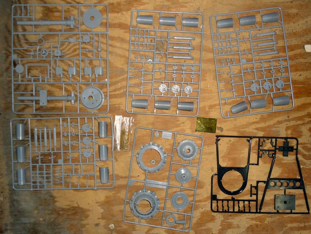
I received the Hagasawa 1/16th scale plastic Sopwith Camel kit, Saturday. A quick reveiw of it compared to the Model Airways kit follows. I bought the Hagasawa kit because it had more detail parts than the Model Airways kit. Engine cowl, front fuselage panels, etc. The Hagasawa kit is all plastic, and the MA kit has wood parts where the original does, though. The Hagasawa kit has many better details than the MA kit, but also lacks several. A major problem is that the wing ribs, for instance are supposed to be shaped like an “I” beam. A central web, with a horizontal web on the top and bottom. The Hagasawa ribs are flat. On the other hand the original plane had metal brackets at all the wood to wood joints in the fuselage. The Hagasawa kit has them molded onto the fuselage sections, the MA kit does not have them. The MA kit has turnbuckles, the Hagasawa kit does not. The Clerget engine had 22 cooling ribs on each cylinder. The 1/8th scale Hagasawa engine kit has the correct amount. The 1/16th kit only has 18, I guess that there is only so much you can do with even a plastic casting. The MA metal casting for the cylinders has only 11 fins. The bolt detail on the Hagasawa kit is finer and close to scale, the MA kit is OK, but the details are a bit larger than scale. Some of the parts in the Hagasawa kit are also finer, like the wicker seat casting. I have not yet decided on whether to build the Hagasawa kit, and ignore the wing rib problem, add the webs at the top and bottom, or use the wing assemblies from the MA kit, on the Hagasawa. Using both very expensive kits to make one model is not appealing, though. I will build the Hagaswawa kit, and probably do the painful process of adding the rib webs. Selling the MA kit and using the money for other goodies, is probably smarter, but more thought has to go on before a final decision. The kit box The box contents, and the plastic parts spread out some. A close up of one half of the engine on the Hagasawa kit.

-
How about a couple of unobtrusive hooks amongst the plaques, then suspend the plans while working, and set them aside when not..
-
I scan the plans one section at a time, then combine them into a single file. Then import them into my CAD program. The Cad lets me adjust size to correct any distortion, and redraw any sections that are not clear, or slightly different on different sheets. it also allows me to draw any additional details I might make, as well as print any section I need during construction. The originals get rolled up, and stored in a cardboard or plastic tube, for safe keeping.
-
Fokker Dr.I by Torbogdan - FINISHED - Model Airways
thibaultron replied to Torbogdan's topic in Non-ship/categorised builds
As a continuation of the discussion earlier in this thread. I just ordered the Hagasawa 1/16th Camel kit. I'll post on the comparison of the details in the plastic and Model Airways metal parts when it arrives, some time next month. I already have the MA Camel. -
1/24th, I built one.
-
Fokker Dr.I by Torbogdan - FINISHED - Model Airways
thibaultron replied to Torbogdan's topic in Non-ship/categorised builds
Le Rhone and Clerget Hagasawa 1/8th scale engine builds. you'll have to copy and paste two of them. https://mbiqmodels.com/2016/03/09/fokker-dr-1-hasegawa-18-part-2-engine/ https://mbiqmodels.com/2014/10/12/sopwith-camel-f1-hasegawa-18-part-1-clerget-9b-rotary-radial-engine/ https://mbiqmodels.com/2014/10/27/sopwith-camel-f1-hasegawa-18-part-2-prop-interplane-and-cabane-struts/ -
Fokker Dr.I by Torbogdan - FINISHED - Model Airways
thibaultron replied to Torbogdan's topic in Non-ship/categorised builds
Liquid plastic cement. -
Fokker Dr.I by Torbogdan - FINISHED - Model Airways
thibaultron replied to Torbogdan's topic in Non-ship/categorised builds
I got the two Hagasawa engine kits. The detailing looks good, at least good enough for me. The Le Rhone 110HP The Clerget 130HP A close up of the cylinder and vale rocker arm parts.


-
Vallejo and AK Weather wood paint and washes
thibaultron replied to KAT's topic in Modeling tools and Workshop Equipment
Is that the AK 259 REALISTIC WOOD EFFECTS , book? -
Fokker Dr.I by Torbogdan - FINISHED - Model Airways
thibaultron replied to Torbogdan's topic in Non-ship/categorised builds
One source I found, said that the Germans would reuse Le Rhones in the DR.1, if they captured any. Similar to your post. -
Fokker Dr.I by Torbogdan - FINISHED - Model Airways
thibaultron replied to Torbogdan's topic in Non-ship/categorised builds
I broke down and bought one the Hagasawa Le Rhones. Should be here next week. Haven't decided whether to keep or resell the Williams Brothers 80HP model. When the 110HP arrives, I'll post some pictures of the parts. I also bought one of there Camel engines, its coming from Canada.