usedtosail
-
Posts
2,423 -
Joined
-
Last visited
Content Type
Profiles
Forums
Gallery
Events
Everything posted by usedtosail
-
 Ok, now I get it. I did use some of that model's transom design, as you may have noticed, but certainly not all those windows. Five was hard enough. Yep, I am trying for 1812 version, so anything you can find helps a lot, even if I at least know how mine differs from known information. Thanks to all.
- 1,354 replies
-
- 1
-

-
- constitution
- model shipways
- (and 1 more)
-
Oh, thanks George for the pictures. You had me second guessing myself. Especially since I glued those on last night before I saw your first reply this morning. I really appreciate your help and for keeping me honest, so to speak.
- 1,354 replies
-
- 2
-
-
- constitution
- model shipways
- (and 1 more)
-
Thanks guys. Tim - that is a good idea using balsa to fill between the bulkheads. I am going more piecemeal but I may use that for some of the bigger areas. George - I am going on the assumption that this main hatch did not have gratings in 1812, but just open skid beams, which again I read somewhere but did not write down the source. I may be completely wrong about that. They probably would have covered this hatch up with something in a blow, however, maybe canvas?
- 1,354 replies
-
- 1
-
-
- constitution
- model shipways
- (and 1 more)
-
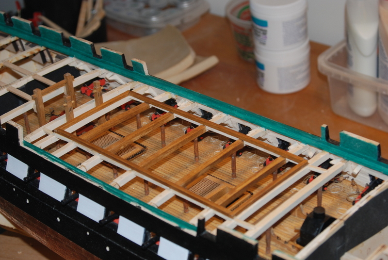
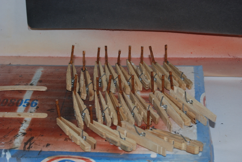
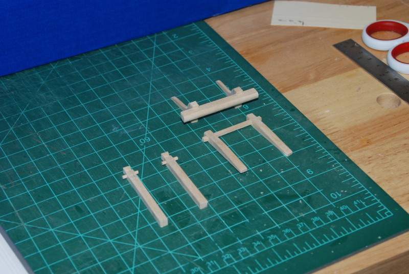
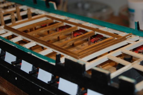
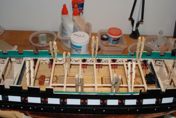
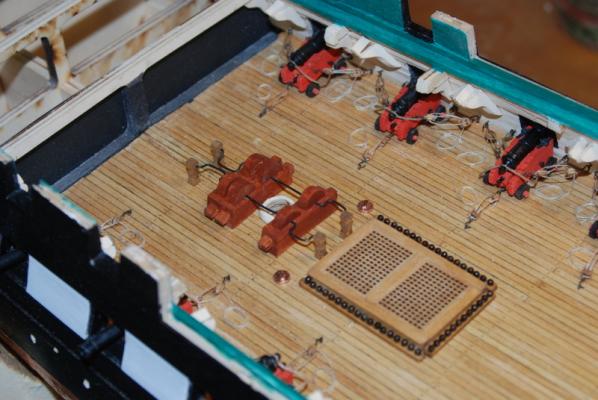
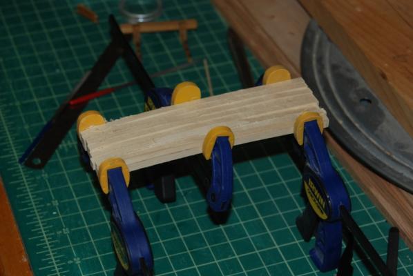
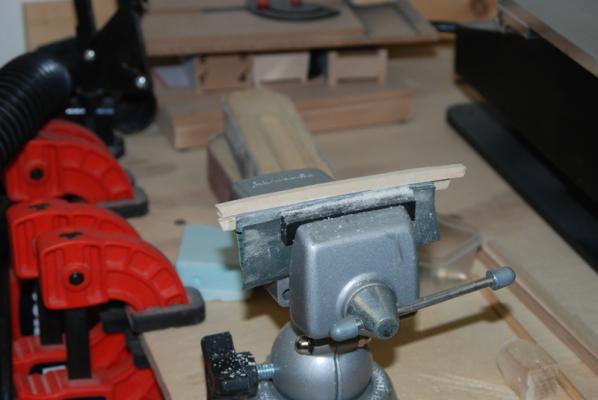
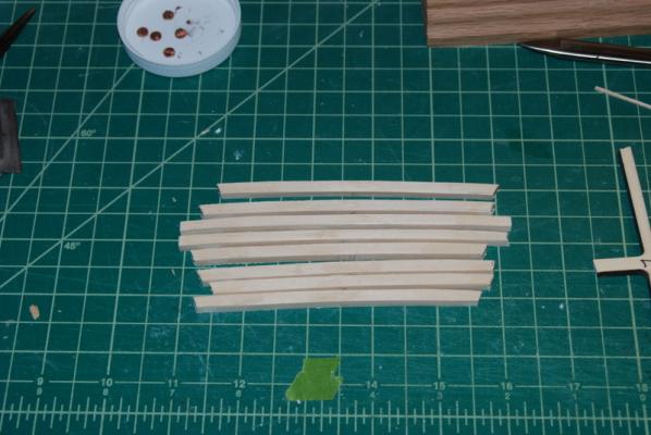
Thanks George and Tim, and the likes. I made up the bottom strips for the main hatch coaming from some square wood strips, using lap joints at the ends. The cross beams that I bent to the old frames stayed at the right curve after I removed the clamps. I stained the coaming pieces and glued them onto the carlings and cross beams, using lots of clothes pin clamps to keep them tight to the carlings. I glued the starboard side piece on first, then after it dried, I glued the other three pieces on. Here is how they came out. You can also see the monkey rail and main bitts in this picture too. I then cut some smaller strips to place on top of these, which will be flush with the inside edges. I stained them last night but have not attached them yet. Here is a preview of how they will (should?) look. I have also been adding supports to the beams and edges for the other spar deck coamings and planking. I have never planked a deck that wasn't on a solid surface, so I wanted to make sure I have solid supports for all the beam ends. I am going to be planking around the coamings like I did on the gun deck, so needed to have supports to glue these to before planking. I have the deck arrangement of hatches I want for the spar deck, so I will be building those coamings next. I am also thinking of adding a rectangular sky light to the stern end of the deck, as in the AOS, and not the octagon shaped one that is on the ship now. Although, somewhere I read that the 1812 version did not have any skylights, but I didn't write down the source of that. The hatches will be the same as on the current ship, except for the larger main hatch. I am not sure if I will put the grating behind the bow sprit or leave that a solid piece of wood. I am leaning toward using a grating though. What do folks think of this deck arrangement plan? Thanks.

- 1,354 replies
-
- 5
-
-
- constitution
- model shipways
- (and 1 more)
-
I haven't tried the Krylon, but I really like the Testors gold and brass paints for brush painting small areas.
-
Very, very nice Bob.
-
Cutty Sark by NenadM
usedtosail replied to NenadM's topic in - Build logs for subjects built 1851 - 1900
Nenad, my heart goes out to you man. I can't imagine the pain you and your children are going through. You have my sincerest sympathies.- 4,152 replies
-
- 8
-
-
- cutty sark
- tehnodidakta
- (and 1 more)
-
Jay, you have been an inspiration. Job well done. Thank you.
- 732 replies
-
- 4
-
-
- constitution
- model shipways
- (and 1 more)
-
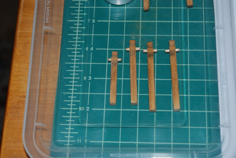
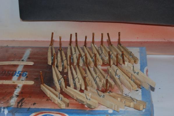
Thanks again George, and also thank you folks who have hit the Like button. So, after some deep thought (OK maybe not so deep) I decided to add whole beams at the ends of the main hatch coamings, mainly because these need to have the same deck round up as the other beams, which means the coamings will need to sit on something curved. So, I made two more beams using sheet wood, then separated the beams into those that will be stained, which are the ones that are seen in the hatch, and those that will be planked over. I stained the center of the stained beams, then masked off the ends. I then painted the ends of those beams and the whole length of the other beams on three sides with off white paint, to match the paint I used on the gun deck sides. I did not paint the tops of any of these beams, as they will be planked over. When the paint dried, I installed all of the beams. I adjusted them for height so I was able to not have to do any fairing once the beams were installed. I then added the beam supports under all these beams. I had made these up a while ago on the lathe from dowel, but I made a few more just in case. I have never had good results trying to stain dowel, so I mixed up some paint to try and match the oak stain, and painted all of the supports. When they dried, I trimmed them to fit under each beam, two supports per beam. I was originally going to add them at the junctions of the beams and the carlings, but since this hatch is so wide they would have been too close to the guns. So, I moved them inboard a bit. I also did not put any under the two extra beams I added because they would have been right behind a gun. it was a bit tricky getting them to line up and be straight in all directions, and I had to remove and reglue a few before I was satisfied with them. After this I added all of the carlings, which I also painted on three sides with off white paint, and I attached the monkey rail to the beam behind the main mast. I had to add two supports behind it to get it the right distance from the main mast. It was still in clamps last night so no picture of that yet. I also soaked two lengths of 1/8" square basswood and clamped them to two of the old beams to get them to the round up for the ends of the hatch coamings. They may spring back too much, but if they do I will bend them to a greater curve tonight.
- 1,354 replies
-
- 9
-
-
- constitution
- model shipways
- (and 1 more)
-
Yes, thanks for sharing this work Jerry. Someday I may tackle one of these ships and I am sure this build log will be most helpful. Congratulations on a beautiful model.
-
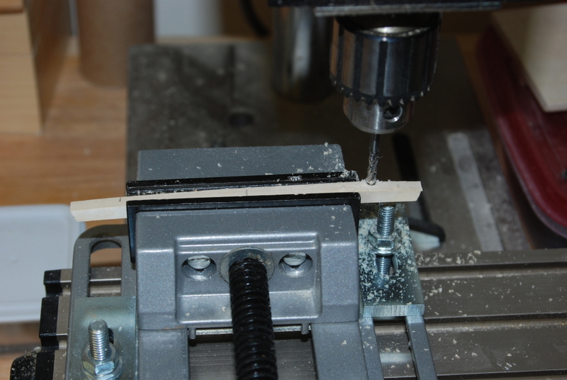
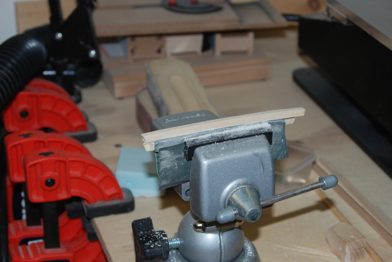
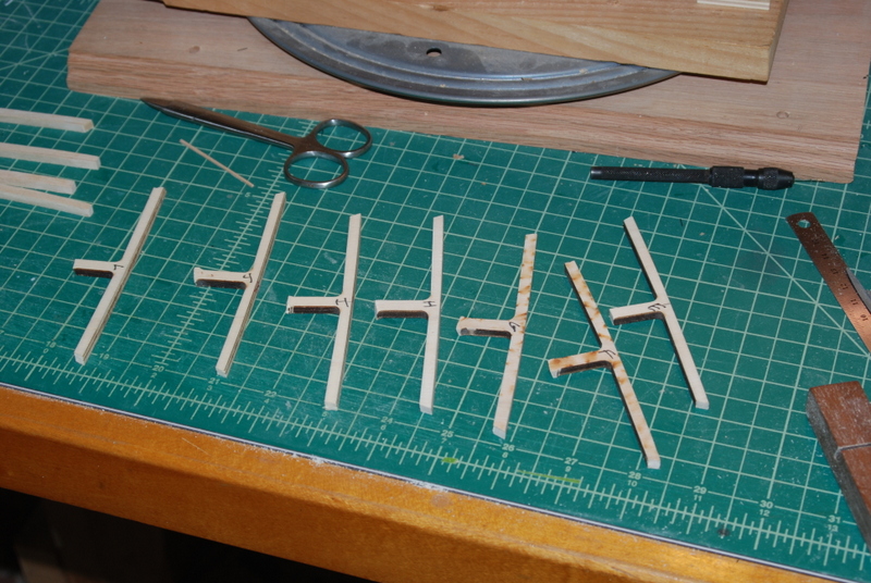
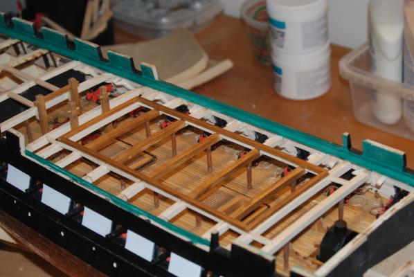
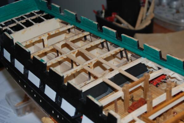
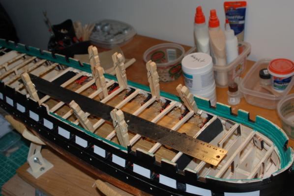
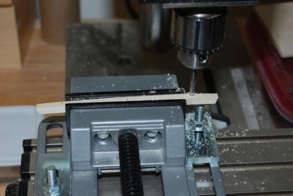
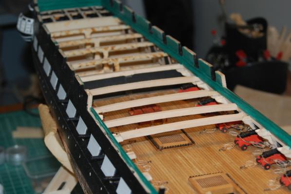
I got into a groove last night so made a bunch of progress. I finished shaping each beam and clamped them in place so I could draw a centerline on each one. Now I have a reference point for adding the carlings to support the hatch coamings. I then marked the locations of the carlings by measuring out from the centerline, and used a 1/8" end mill bit in the drill press to cut the slots for them. I set the depth of the cut by placing the bit so it just touched the beam, then set the depth stop of the drill press to .09". I could then just replace each beam in the vice so it was just touching the end mill and line up the bit using the XY table. I had to switch the beams to the other side of vice for the opposite cuts, and I found it was faster to just loosen the bolts holding the vice to the XY table and move the vise then to rotate the table all the way over. I did two beams at a time this way so there was less switching from side to side. I then used a small chisel to square off the backs of the cuts as best I could and clamped the beams back into place. I cut smaller pieces of wood for the carlings and fit them in the slots. Here they are in place but nothing is glued down yet. Not as good as you masters of POF are doing, but since these joints will be planked over I am OK with them. I will have to work on my technique if I do ever try my hand at open POF construction, though. These pictures give you an idea of the size of the hatch I am adding, which is quite a bit wider than the hatch on the current ship and ME plans. This hatch size came out of the AOS book. I still have to work out how to support then front and back coaming pieces of the hatch, as these are between frames. I will probably add another piece, like a long ledge, between the carlings between those beams, with a little extra toward the front and back to support the ends of the deck planks there. I also have to figure out how I want to finish these beams. I am thinking of painting all of the beam sections that will be planked over off white on the sides and underneath to match the paint on the gun deck side planks (ceiling?), and stain the sections that will be exposed in the open hatch with oak stain. The order of construction and staining/painting still needs to be worked out.

- 1,354 replies
-
- 8
-
-
- constitution
- model shipways
- (and 1 more)
-
Brig Eagle by robnbill - 1:48
usedtosail replied to robnbill's topic in - Build logs for subjects built 1801 - 1850
Wow, you have been busy Bill. It all looks great. -
Good to see you back at it, Bob, She is looking wonderful.
-
Thanks Boyd and Sal. Your Bounty and Syren builds, respectively, are coming together very nicely. Thanks George. I am going to plank around both sides of the main hatch, but leave the hatch open except for the skid beams inside. I am going to have the launch being towed behind when I mount it, so you will be able to see the gun deck through the main hatch. That's my plan for now anyway.
- 1,354 replies
-
- 3
-
-
- constitution
- model shipways
- (and 1 more)
-
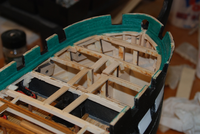
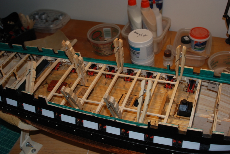
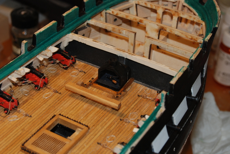
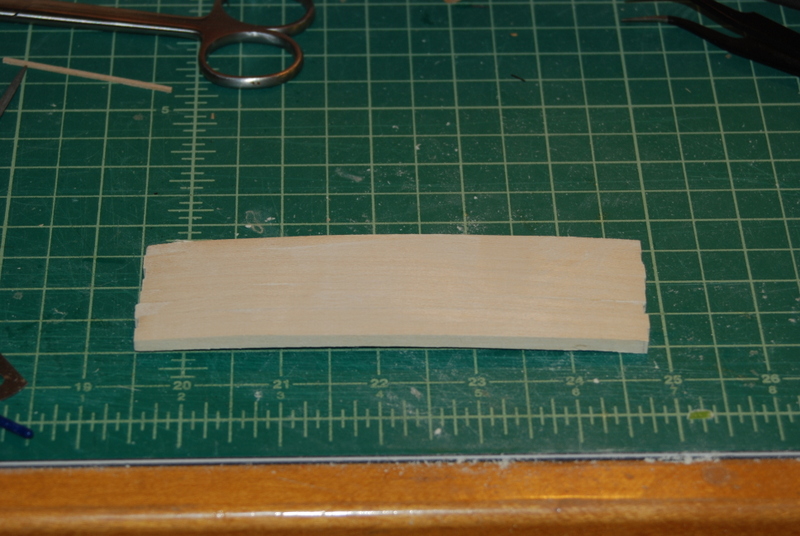
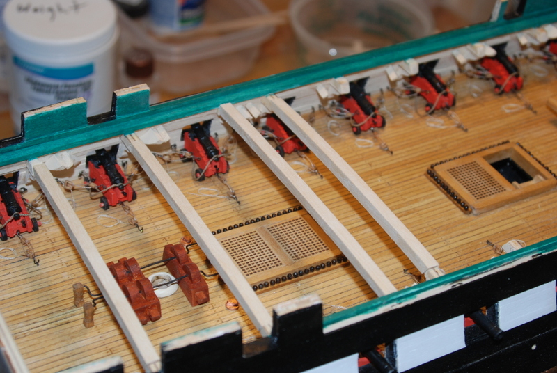
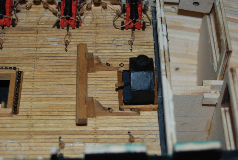
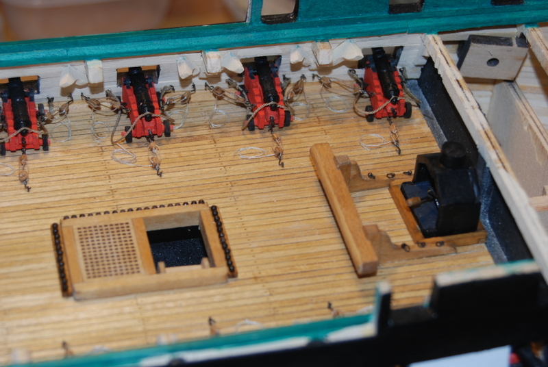
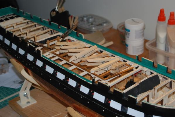
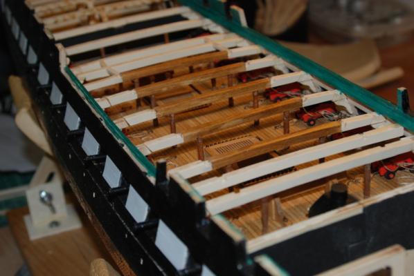
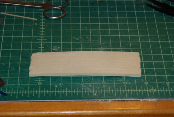
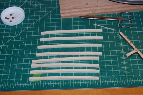
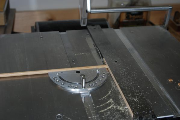
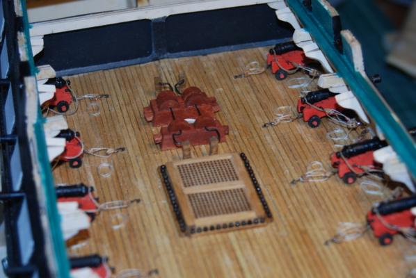
Thanks Steve and George, and for the likes, too. I finished up the gun deck last night, for real this time, unless I mess it up with the work going on above it. I made new coaming sides for the bigger stove, stained them and glued them in. I added more to the front of the stove, painted it black and glued it into the coaming, them glued the riding bitts back in. One side of the bitts kept coming up from the deck, so I came up with an on the spot clamping technique that worked a treat. So here is the new stove arrangement with the chimney the right distance from the fore mast, so the spar deck hatch will be in the right place. And for completeness, the pump area with the ammo scuttle covers in place. I then started on the spar deck beams that will go over this whole area. My first attempt was to cut out a single beam, using the old beams that I cut out over a year ago as a template. I traced it onto a piece of 3/16" basswood sheet, then cut it out with the scroll saw. I sanded the top to final shape, then attempted to use the thickness sander to get the underside to its final shape. I found that because the piece is curved, any little movement up and down caused the thickness to change, so it was coming out too thin is places. I decided that since i just got the thickness sander I am going to need more practice with flat strips before I attempt curved ones. So plan B was to roughly cut out all the beams on the scroll saw and lightly glue them together side by side. When that was dry, I sanded the tops together using the belt sander, and the undersides using a large sanding disk in the drill press. I then soaked the block in alcohol for about an hour and separated the beams. On a couple I had to wedge an X-Acto knife blade into the ends to get them started. As you can see, they were still a little rough. I then cut them to length, using the old beams as templates. Here are the old beams, and the beam extensions that I left on the bulwarks to hold up the new beams. I cut these a little long so I could sand them into a good fit. I don't want to have to do a lot of sanding of the beams once they are in place because I don't know how to keep the dust from getting onto the gun deck, so I am trying to fair them as much as possible off the model before attaching them. I still did not like the way the undersides looked, so I took some sandpaper and placed it on top of one of the old beams and clamped them into a vice, then sanded the underside of each beam. This worked pretty well and the beams looked much better. The next picture has a new beam on top of the sandpaper being sanded. Here are some of the beams in place before I sanded the ends. Still more work to do but they are getting there.


- 1,354 replies
-
- 8
-
-
- constitution
- model shipways
- (and 1 more)
-
That is a beautiful looking ship Jerry. Enjoy your vacation.
-
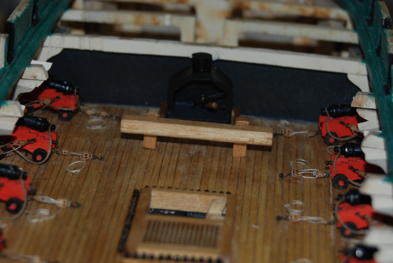
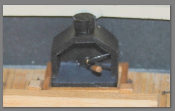
Here is a better picture of the inside of the stove: Sorry, I couldn't resist.
- 1,354 replies
-
- 6
-
-
- constitution
- model shipways
- (and 1 more)
-
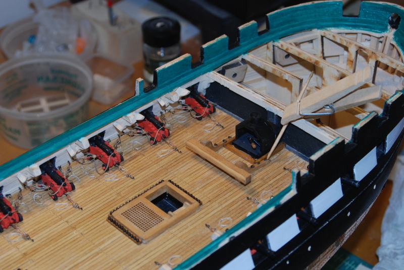
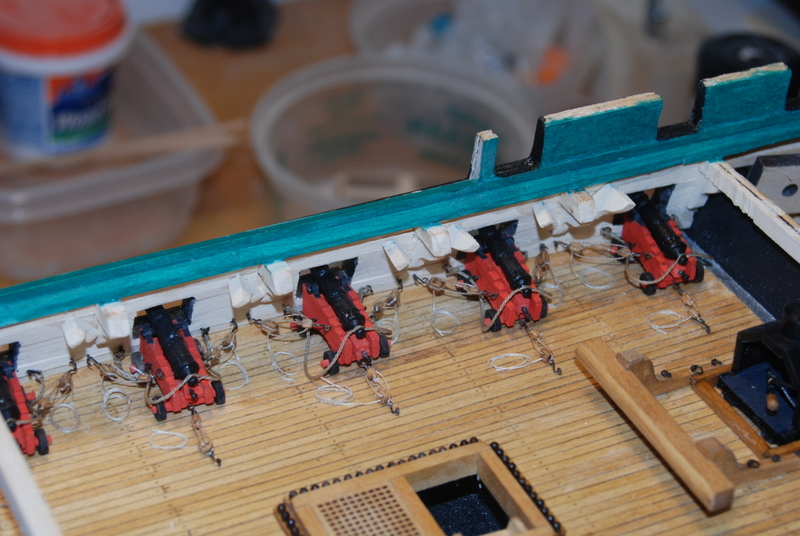
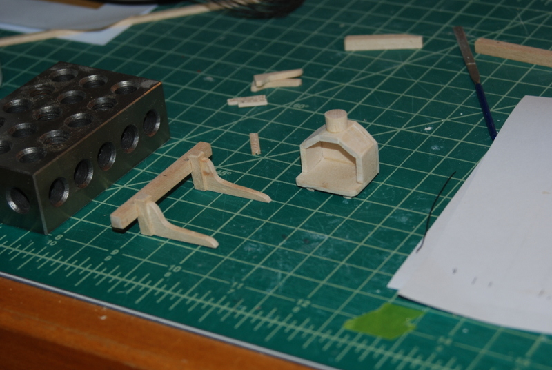
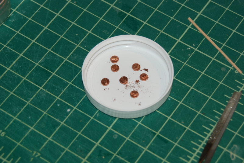
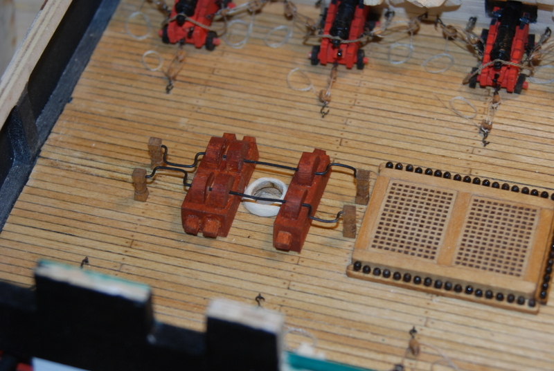
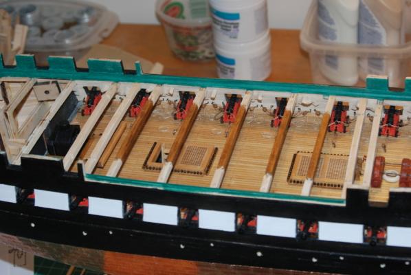
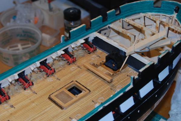
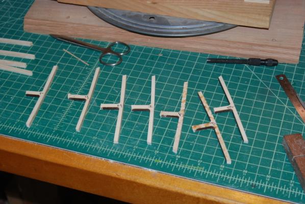
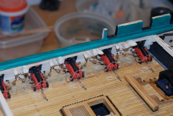
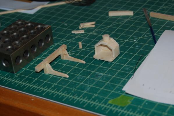
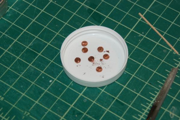
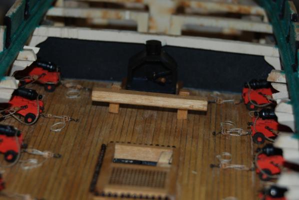
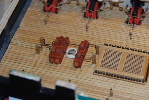
Here are some pictures of the progress so far on the gun deck. I thought I was almost done, but read on... I made up the stove, aft riding bitts, and main topsail sheet bitts. There were all finished with oak stain. As you can see, one is cut off a little short, so I made two more so I have the fore bitts too. I drilled six holes for the simulated sieves and connected them with an awl. They are only 3/16" wide so too small for me anyway, to make from thin layers. I also made up the ammo scupper covers, using slices of dowel that I cut with the Byrnes saw. I added a small strip across the top, which is used to open them on the real ship, and painted them with Testers Brass enamel paint. I have to say that these metal colored paints like the gold and brass really cover nicely, as opposed from the ME brass paint that doesn't cover well at all. I added the pot holder to the stove using some black wire and a bent eyebolt as a hook. Here are pictures with the riding bitt, stove and coaming in place. The problem is that the stove is too far forward for the chinmey to line up with the hatch and stove pipe on the spar deck, so I am going to remove them, remake the coaming, and add a box to the front of the stove. It would have good to check this BEFORE I made them, and certainly before I glued them in place! Sheech... You can also see the cannon ball racks in place with the cannon balls. Here are pictures of the updated pumps with a straight wire between the pumps around the main mast. After I clean up the stove situation next week, I will be started to make the new deck beams. I kept the old beam sections that I cut off over a year ago and will use them as templates for the new beams. I am going to be cutting these from basswood sheet, and will shape them up in the new thickness sander I got for my birthday. I can't wait to play with that new toy. Have a great weekend, all.


- 1,354 replies
-
- 8
-
-
- constitution
- model shipways
- (and 1 more)
-
Brig Eagle by robnbill - 1:48
usedtosail replied to robnbill's topic in - Build logs for subjects built 1801 - 1850
That is looking great Bill. I think you have achieved a good balance with what you are leaving open. -
I have been working on finishing up the gun deck details, and will have pictures soon. Thanks to Jay (Modeler12) I am adding the ammo scuttle covers, which are not quite done yet. I also am finishing up the stove and did some work on the main mast base, after making a tenon in the large dowel supplied for the main mast. I figured I better be able to fit this in place now before adding the spar deck beams and loosing the access to this area. I was going to make a bigger main mast coat for this deck, but there is not enough room between the pumps for one much bigger. I did replace the two handles between the pumps with straight wire because with the mast in place, there would not have been enough room between the handles and the mast. I finished the belaying pin plan and it looks like I will be good with 11 pins on the U shaped rail, as shown on the plan, and not have to add pins to the monkey rail at the main mast. Also, six pins in the spider rail around the mizzen mast will be OK. This is all because there are enough belaying pins on racks on the bulwarks to take the lines I will need to rig, with some to spare. of course once I get into the actual rigging this may change, but I am not going to worry about that now. The next thing I need to do is finalize the standing rigging lines I need to rig, then figure out what sizes of line to use for each of standing and running lines. Then I will figure out how each of the lines will be run and how many blocks I will need of each type and size. All of this can be done as a background task while I am still working on the deck furniture and bow rails, but will need to be done before I start building the masts and spars.
- 1,354 replies
-
- 2
-
-
- constitution
- model shipways
- (and 1 more)
-
Very nice build Dan. I learned a lot from your techniques, especially the sails and flag.
-
Nice info on the barrels and ammo scuttles. Do you think those scuttles have always been in the spar deck or could they have been added in later refits of the Constitution?
- 572 replies
-
- 1
-
-
- constitution
- frigate
- (and 1 more)
-
Yeah George I do too. But, this will be about it for the gun deck. I am now thinking of leaving the ships boat off the hatch beams and show it along side the ship, so more of the gun deck can be seen. Maybe towed behind if that doesn't make the case even bigger than it needs to be now. We shall see...
- 1,354 replies
-
- 2
-
-
- constitution
- model shipways
- (and 1 more)