usedtosail
-
Posts
2,421 -
Joined
-
Last visited
Content Type
Profiles
Forums
Gallery
Events
Everything posted by usedtosail
-
 Very nice work on the beams. I am coming to the point where I have to make a few beams for the Connie, so this is a very timely tutorial. Thanks.
- 456 replies
-
- 2
-

-
- finished
- bomb ketch
- (and 2 more)
-
Oh, and thanks for the information Buick Nut. I just recently saw the President plans in one of Chappel's books, which is pretty compelling evidence for six windows across the transom, but it was easier for me to just make 5.
- 1,354 replies
-
- 1
-
-
- constitution
- model shipways
- (and 1 more)
-
Thanks Boyd. I was hesitant about starting a build log because I still feel so new to this, too, but I really enjoy it now. I love that it is helping other builders like yourself, but I learned a lot from other build logs too, and still do. I have to say, your Bounty is coming along really nicely and I am going to be following along with your log because I can learn from you too. Your interior details are just amazing. For the rest, I should have an update tomorrow. I have been doing some work but have not had time to get the pictures off the camera.
- 1,354 replies
-
- 1
-
-
- constitution
- model shipways
- (and 1 more)
-
Captain, I am glad my pictures can be of help. You are on the same track I was - many redos, reusing pieces of parts and adding new wood to them, etc. In the end, I liked the result and yours looks like they will do nicely. So far, I think this was the hardest part of the build, so hang in there and you will be through to more fun stuff.
-
Popeye, that is some magnificent work. I love the color scheme and the details you have added. Well done, sir.
- 956 replies
-
- 2
-
-
- andrea gail
- trawler
- (and 1 more)
-
Jeff - Thanks for looking in and all the likes. I'd say your Fair American is more than fair, although you can't fair too much on these ships . All of the planking is butt jointed on mine, so no overlaps. I am not sure I have seen overlapping planking before. The strip chooses the ship! - I love it! George is right - it is finding small enough balls for the cannon balls that is the issue. Ball bearings work great, especially stainless steel. And Bill's method of heating the balls before blackening works great, which is the method I used.
- 1,354 replies
-
- 3
-
-
- constitution
- model shipways
- (and 1 more)
-
Hi George. Here is another link you might find useful, if you haven't already seen it : http://www.captainsclerk.info/ The Navy used to have the contents of the Constitution CD on a web page, but it seems to have been taken down.
- 1,354 replies
-
- 2
-
-
- constitution
- model shipways
- (and 1 more)
-
Glad to be of help Jeff. Those clips really do come in handy. I just had a look at your Fair American build. You are off to a great start.
- 1,354 replies
-
- 1
-
-
- constitution
- model shipways
- (and 1 more)
-
In the caption to the picture, it says the wale planks are 3/32" x 5/32", but it still doesn't make sense. My guess is that they are not wider, but thicker by 1/32" than the previous planks.
-
You will. Maybe the stuff on the CD will help you decide.
- 1,354 replies
-
- 1
-
-
- constitution
- model shipways
- (and 1 more)
-
Your welcome George, There is some pretty interesting stuff included. Its fun to poke around on it.
- 1,354 replies
-
- 1
-
-
- constitution
- model shipways
- (and 1 more)
-
Thanks George. The CD can be bought from the US Navy museam store web site - http://museumstore.navyhistory.org/CD-Constitution-Plans-p/618.htmor the Constituion museam web site - http://store.ussconstitutionmuseum.org/products/uss-constitution-plans-for-model-ship-builders-and-general-researchers.
- 1,354 replies
-
- 2
-
-
- constitution
- model shipways
- (and 1 more)
-
Thanks Tim and Lukas. Lukas thanks for the description of your work. I came across your build log when I was about half way through with these guns and it just blew me away how realistic yours looked. I figured they were glued to the deck and I will try that approach on the spar deck guns. Weighting them down is good to know too.
- 1,354 replies
-
- 2
-
-
- constitution
- model shipways
- (and 1 more)
-
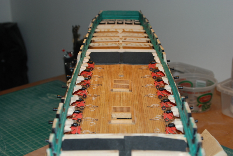
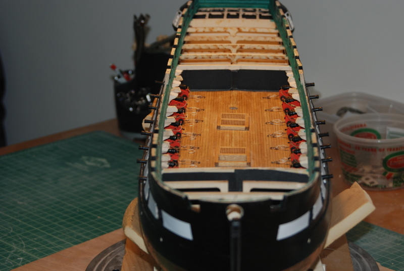
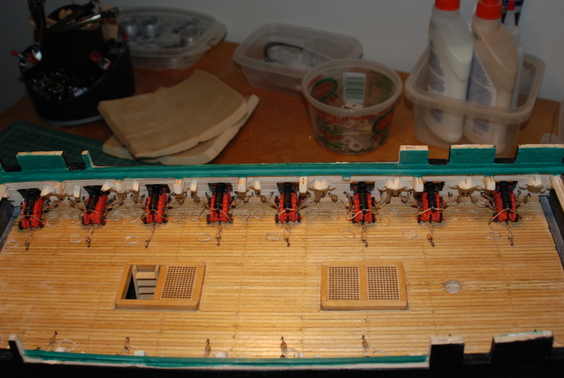
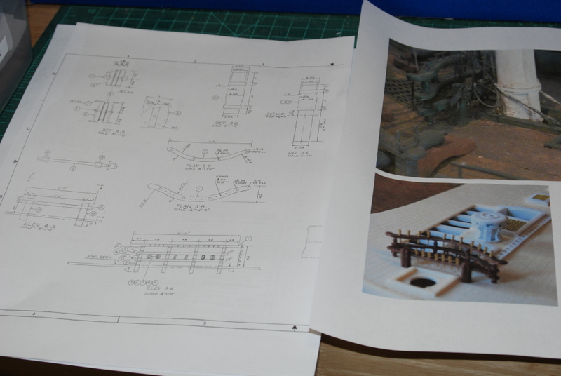
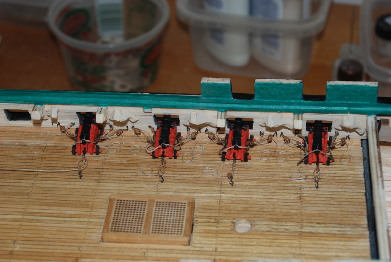
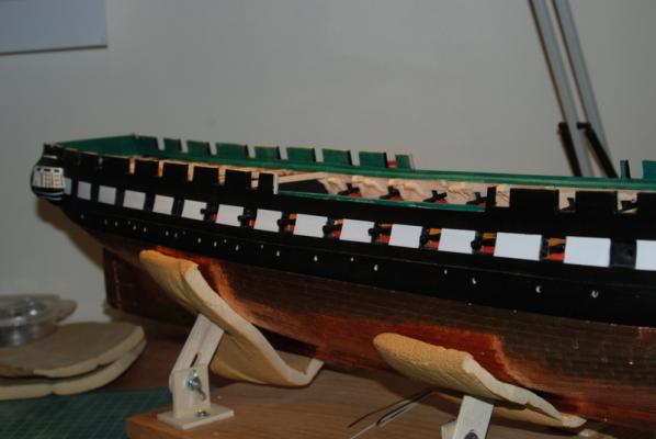
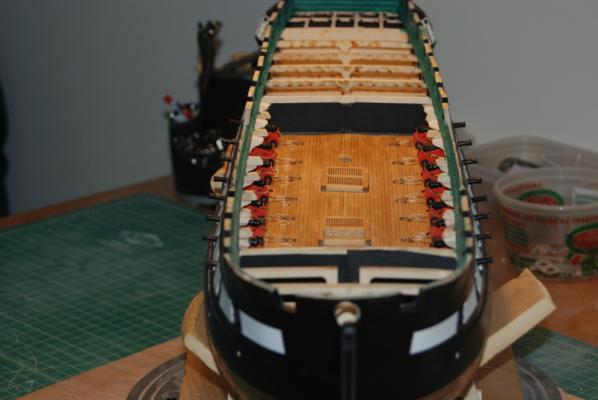
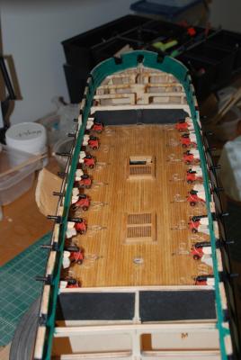
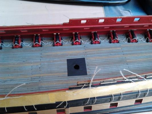
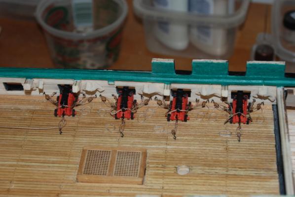
Thanks for the likes. I finally finished installing and rigging the starboard side gun deck guns. It's not that it was time consuming, I just didn't have the time to work on them lately. Lots of stuff going on outside the workshop, including my son's college graduation this weekend and getting the lake house ready for summer. But, I have some time this week to work on her. Here are the starboard side guns, from inside and outside. And here are all the guns on the gun deck. Now for some self criticism. I have always had a problem with the breaching ropes looking realistic, as they want to stick out from the sides of the carriages. Here is what I think looks very realistic, from Lukasvdb's Le-Superbe build. For one thing, these breaching ropes are longer and drape nicely on the deck. I think they are probably made with nicer rope too that is more flexible than the nylon stuff I made. I may try to do the breaching ropes on the spar deck this way, using cotton thread to make the breach ropes instead of nylon. The next task is to add the chain pumps that I made earlier to the gun deck. I have also started to think about making this U shaped main rail, which is not what is on the ship today. I found the plans for it on the Constitution CD, so I have everything I need to build it. I thought the legs for this would go all the way down to the gun deck or below, but the plans only show them going 12" into the spar deck. I am going to make the lower monkey rail in front of the U shaped main pin rail go all the way to the gun deck though. I am getting to the fun stuff now.


- 1,354 replies
-
- 6
-
-
- constitution
- model shipways
- (and 1 more)
-
Brig Eagle by robnbill - 1:48
usedtosail replied to robnbill's topic in - Build logs for subjects built 1801 - 1850
Bill, so this is what you've been up to since the Connie. I had no idea. This is a nice step in the right direction. I have actually read the dissertation on this ship and found it fascinating. You are doing a great job on the framing. I hope to be able to scratch build some day and will use your gantry method for sure. -
First time rigging - being organized
usedtosail replied to RichardG's topic in Masting, rigging and sails
I use the same approach to rigging (I am also a software developer, too). I make a spreadsheet of the rigging in the order that it is to be done in. This order changes as the rigging progresses, however, as I see what kind of tight spots are being created. One bit of advice I would add is to look at the many practicums that are available, especially those by Chuck Passaro. You can find these on the Model Expo web site for the Phantom and Sultana models, among others. I think he has some on the Syren web site too. The order that he uses is basically the same order I use, but tailored for whatever model I am working on. I usually still spend quite a bit of time filling out the spreadsheet, but it makes the rest of the rigging process so much easier. -
Thanks George. I started with 1/8" double blocks and filed/sanded them down to roughly 3/32" I already had 3/32" single blocks, so I used them for the other side of the tackle. At this scale, 6" blocks would be 5/64".
- 1,354 replies
-
- 1
-
-
- constitution
- model shipways
- (and 1 more)
-
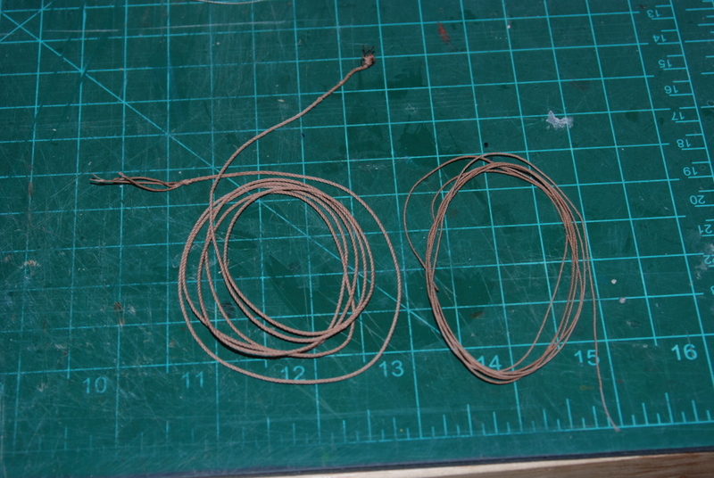
George, you were correct. After more experimentation last night, I was able to make some nice rope that did not want to untwist. I twisted the individual strands longer than pulled the rope to harden it after it twisted up. I then got brave and tried to make thicker rope from the thinner ropes. The first attempt was a disaster, as I did not twist the individual strand enough. The second attempt, after having to remake the individual ropes again, was better, but still did not look good. I quit for the night and this morning I tried it again using a heavier weight. This was a success. I made these ropes with white thread, so I stained them brown by soaking them for a minute in brown shoe polish, wiping off the excess, and letting them dry. OK, since I was taking pictures I figured I'd show where I was with the starboard guns. I did more rigging of them after the rope making experiments yesterday and today.


- 1,354 replies
-
- 8
-
-
- constitution
- model shipways
- (and 1 more)
-
And I will update my question and answer. The additional twisting of the individual strands did produce rope that did not want to unwind. I then experimented with making thicker rope from these thinner ropes, rotating them in the opposite direction. After a couple of unsuccessful attempts, I was able to figure out the right weight and amount of twist to make decent rope. I am really pleased with this rope walk and look forward to making the ropes for the Constitution.

-
I haven't tried that George, but I will give it a go. Chuck hardens his by stretching it after it is made while still on the rope walk. Also, putting enough tension on the individual strands before twisting them together seems to be the trick to keeping rope wound. Looks like I have more experimenting to do.
- 1,354 replies
-
- 1
-
-
- constitution
- model shipways
- (and 1 more)
-
Ok, I am going to answer my own question. After doing a search on "unwind" in the forums I found a few threads that talk to this problem. It looks like it is the amount of winding of the individual threads that is the trick to not unwinding. So, I will try adding a lot more twist to the individual threads before releasing the weight.
-
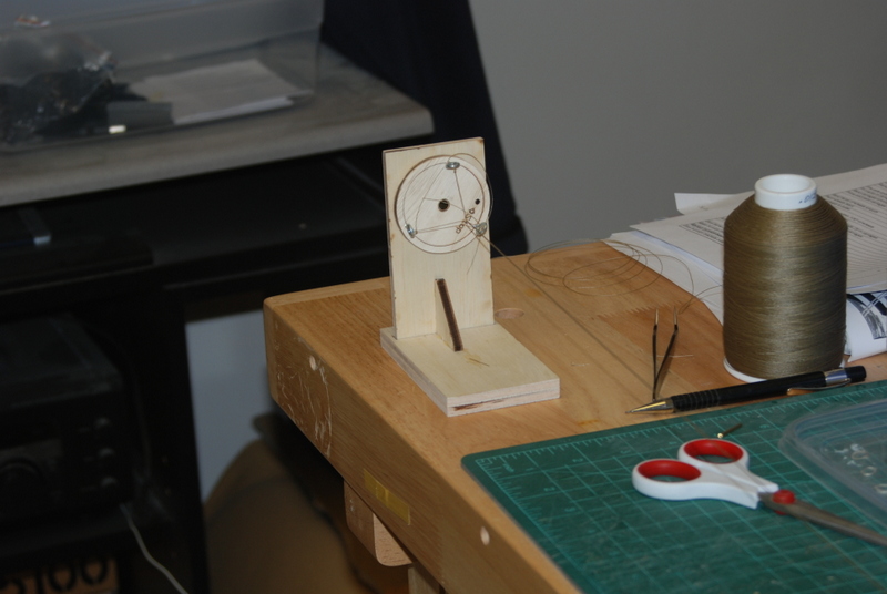
Yep, using a disk with notches works really well with small threads. I made one out of cardboard. No problem with them breaking. I do have a problem with the rope wanting to unwind itself. Has anyone solved that problem?
-
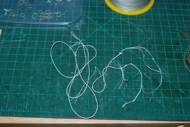
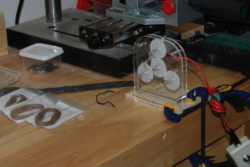
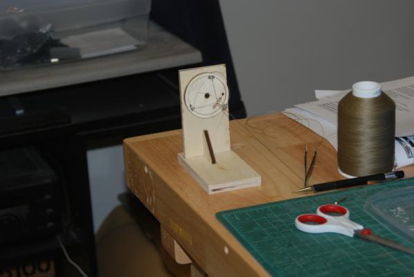
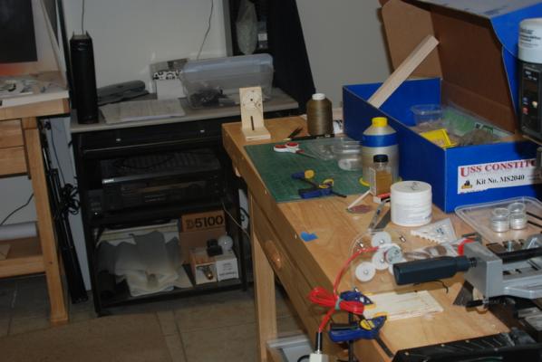
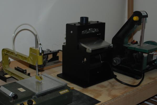
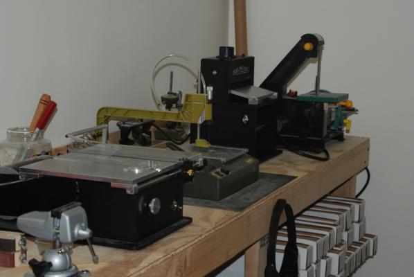
Nothing new to show on the Constitution. Installing and rigging the starboard side gun deck guns continues, but it looks just like the port side, so no new pictures. I do have a couple of new toys, er tools, in the workshop, thanks to my very generous Admiral. The first is a new rope walk from Dormanoff. As I mentioned previously, I wanted to try using this horizontally like the ME rope walk, using the back end of the ME rope walk. Like this: I have to say it worked well in this configuration, pretty much just like the ME set up but with less work. I still had to manually crank the other end after the threads were tensioned, but that went pretty quickly. In the first photo you can see some samples of Chuck's rope from Syrene, which is what i am using as a goal. My rope is not there yet, and still wants to unwind if left to itself. I then tried the new rope walk in the vertical position with a weight on the other end, like it is intended. It worked really well this way, too. The resulting rope looks better to me than the horizontally produced rope, but still wants to unwind. It is easier to set up in this configuration, too, so I think this is the way I will use it in the future. The other new tool is on the bench but I haven't used it yet. This is the Byrnes thickness sander. There have been a couple of times in the Connie build where I could have used it, so I should have a chance to try it out soon. It does look good next to the other power tools, hee hee... I'll get some pics of the cannons when they are fully rigged, I promise.

- 1,354 replies
-
- 7
-
-
- constitution
- model shipways
- (and 1 more)