usedtosail
-
Posts
2,420 -
Joined
-
Last visited
Content Type
Profiles
Forums
Gallery
Events
Everything posted by usedtosail
-
 Great restart captain. I know what you mean about what will be seen on the gun deck, which is why I only did a partial deck instead of the whole thing. Those keel details you made look great.
 -
Nice work on the waterways and plank sheer. Will you be adding cannons to the gun deck?
-
A Viking ship, huh. Have you been watching the show on History channel? It's got me thinking about wanting to build a Viking ship.
-
Thanks guys. BTW, its Nenads birthday today too. I just got back from a week vacation in the San Francisco bay area, so no updates this week. We had a great time. Spent the second half of the week in wine country. Have some bottles being shipped to me here, now that MA is finally allowing shipments of alcohol.
- 1,354 replies
-
- 2
-

-
- constitution
- model shipways
- (and 1 more)
-
Happy Birthday, Cap'n Bob
-
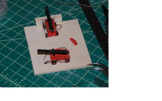
Just a quick update. I assembled the first two cannons for the starboard side gun deck last night, pinning everything, and it worked great. I first used a barrel without a pin to locate the position of the quoin, then drilled a hole through the quoin and the carriage and put a piece of 28 gauge wire through with some CA on it, as well as CA on the underside of the quoin. I then put some pencil lead on the end of the pin in the barrel and used it to mark the location for a hole in the quoin for the barrel pin. I drilled that hole and glued the barrel in place with CA on the carriage at the trunnion cut outs, the barrel pin, and the underside of the barrel where it rests on the quoin. After the glue dried, this was a very solid assembly. I added the paper brackets and glued them onto the gun deck. Now I wish I had made the port side cannons this way. I will certainly use this method for all future cannon on this and following builds.
- 1,354 replies
-
- 2
-
-
- constitution
- model shipways
- (and 1 more)
-
Thanks so much, Jerry, but your build log is pretty terrific. I am glad you reminded me about the differences in kits. That could have been very confusing.
-
Yes George, I pinned the port carriages to the deck and will be doing that on this side too. You can't see it in that last picture because the quoin is covering the pin.
- 1,354 replies
-
- 2
-
-
- constitution
- model shipways
- (and 1 more)
-
Thanks Jerry. I will be honored to follow in your footsteps.
-
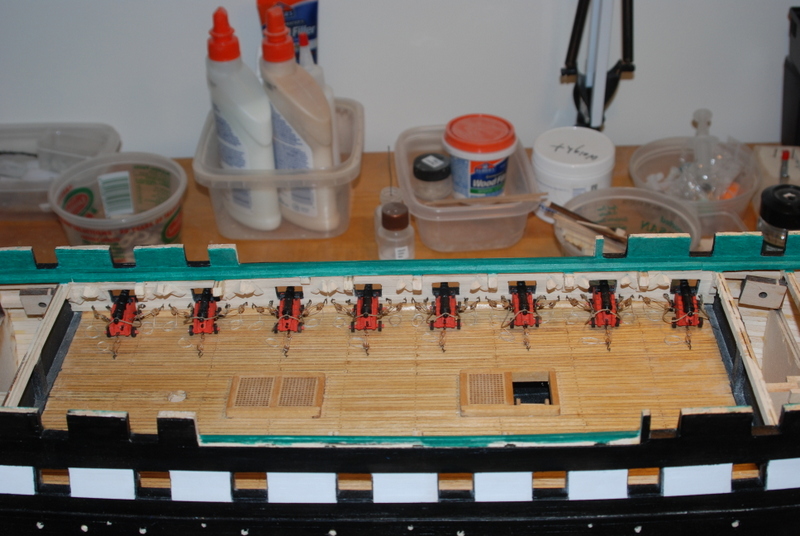
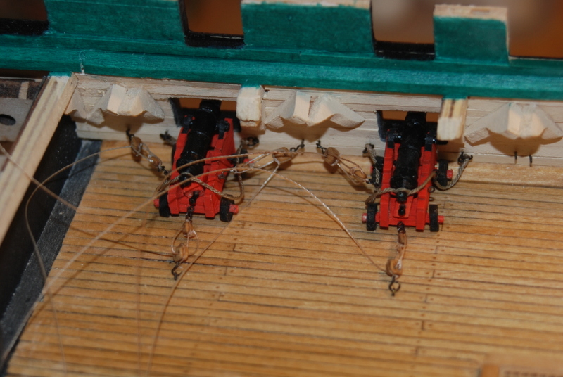
George I am pretty excited to see the ropes from Chuck. I am hoping his smaller ropes will look better when in blocks, as the stuff I have is kind of stiff and wants to stick out away from the blocks. Steve - I don't know about that strong, but hopefully it will lessen the oops factors as I proceed. Last night I did find some rope I had from an older kit that matches what I made really well, so I am using that for the starboard side breaching lines. Firstly, I tied up the loose ends (literally?) on the port side last night, so here ii is with all the rope coils installed: From the outside, I am pretty happy with the alignment of the guns. The head on shot shows some reflection from deep inside the gun barrels that doesn't show up in real life: I was able to drill into the underside of the barrels. I made a starter hole with a pin vise then put one of the barrels into my drill press vise and drilled deeper. This worked great except that these barrels are so soft that the vice kind of crushed the details on the sides of the barrel, so for the second barrel I drilled the whole hole by hand. I glued a piece of wire into that hole and will make a corresponding hole in the quoin for the other end. I suppose I should also pin the quoins down to the carriage, which I can do when installing them by just drilling through the quoin and the carriage base and putting a piece of wire through the holes. You can also see in this picture the how the line I found for the breaching ropes (right) compares to the line I made (left). I am glad I can continue with the guns, but there is still many other pieces that I can work on if I had to wait. I ordered the line from Chuck yesterday and it has shipped today, so I would not have had to wait too long. That is great service. I also ended up ordering the rope walk to play with, but since that is coming from Russia I have a feeling it will take a little longer.
- 1,354 replies
-
- 6
-
-
- constitution
- model shipways
- (and 1 more)
-
Your Half Moon looks great, Jerry. That is going to be my next build, but at the rate I am going with the Constitution, I'll be retired first, which should be in about 7 years.
-
Well, some trouble in the ship yard last night. I did manage to get all of the port side cannons installed and rigged, with just a few loose ends to cut off and rope coils to add tonight. I ran out of breaching rope for the starboard side guns, so I thought I would just whip up another length using the ME rope walk. Well, after much frustration the rope walk basically disintegrated. There was so much play in the gears that they kept binding and finally the handle just broke off. I tried taking it apart to see if I could get the gears to mesh better, but to no avail. I now have a choice to make. I can use some other rope I made that is not quite the same as the breaching lines on the port side, but looks similar, or I can wait. I did just order some rope from Chuck, so I can at least wait to see if that matches better than what I have. I also have an inquiry into Domanoff for his Prosak vertical rope walk, which looks pretty good. I was wondering if anyone has tried to use his rope walk horizontally, like the ME one. I could use the other end from the ME rope walk, which works fine, with it. I am thinking that even if this doesn't work, I can still use the Prosak as it was intended. Then again, I could just buy my rope from Chuck, but I kind of like making it too. Decisions, decisions... I also have to be very careful around the hull now, because if I accidentally bump one of those cannon barrels it will most likely come loose from the carriage. Not a big deal now that I have access to them from above, but once I plank the spar deck it is going to be very difficult to get at them through the gun ports. I am wondering if I should have pinned the barrels to the carriages when I assembled them. Have people done this? It would require drilling a hole into the barrel from underneath, which shouldn't be hard since it is soft metal. I may try this for the starboard side guns.
- 1,354 replies
-
- 2
-
-
- constitution
- model shipways
- (and 1 more)
-
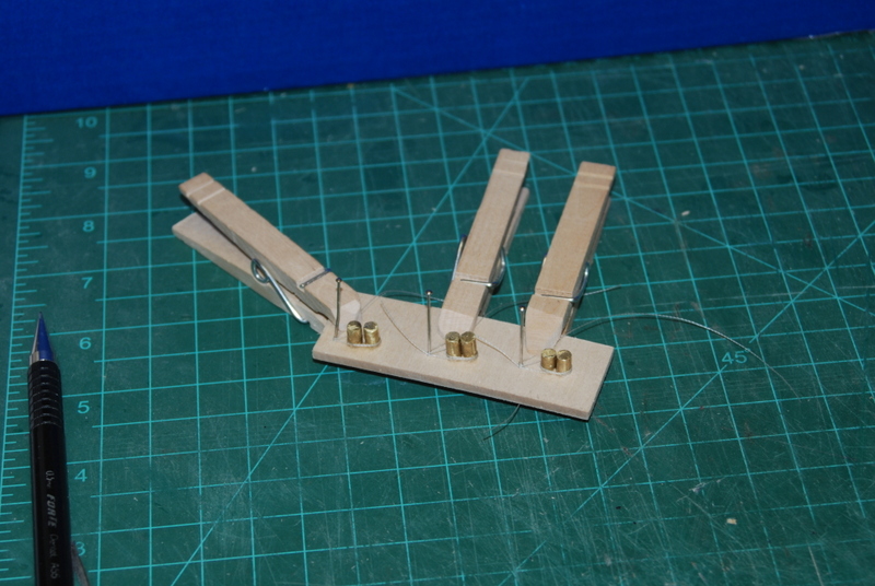
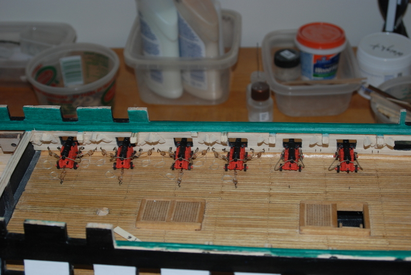
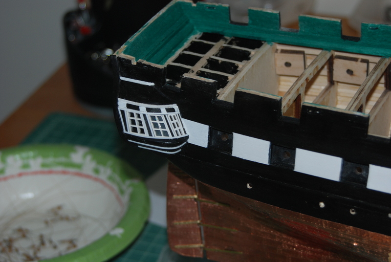
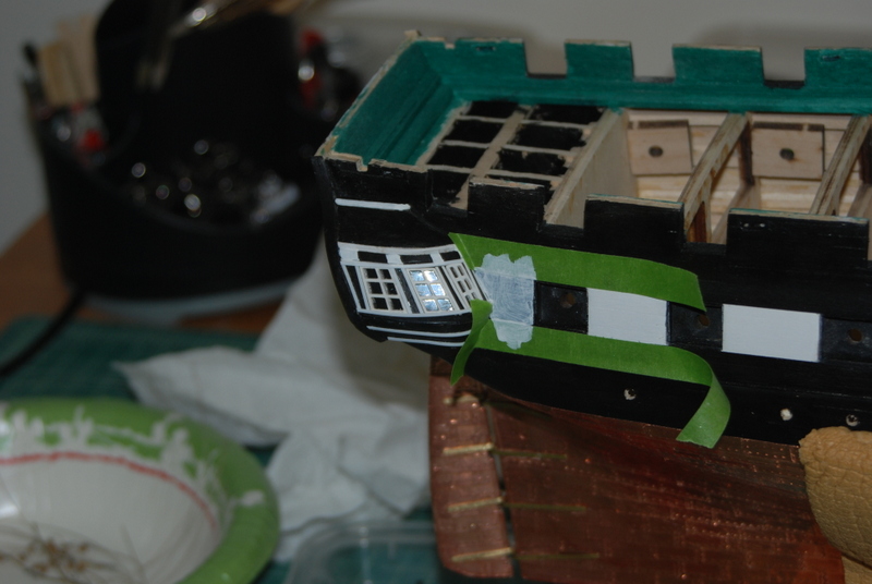
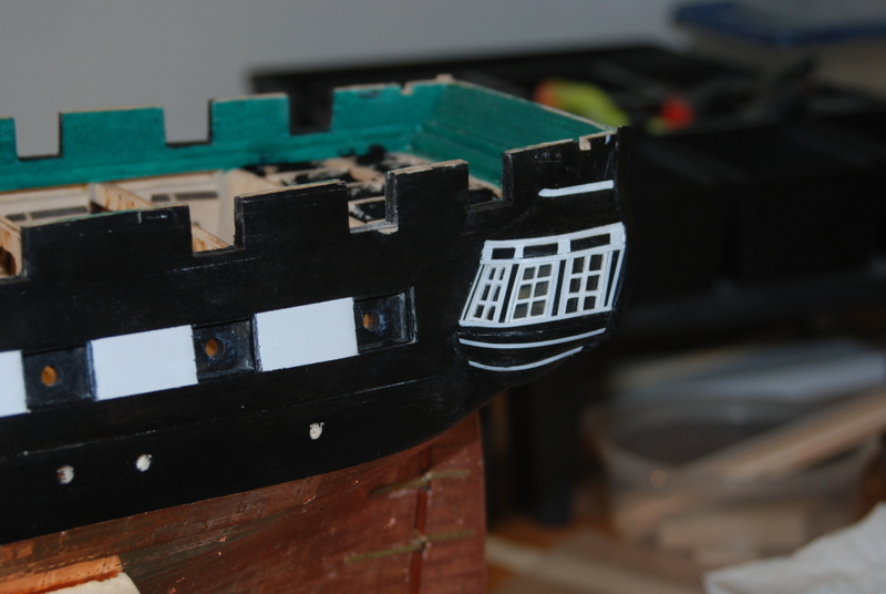
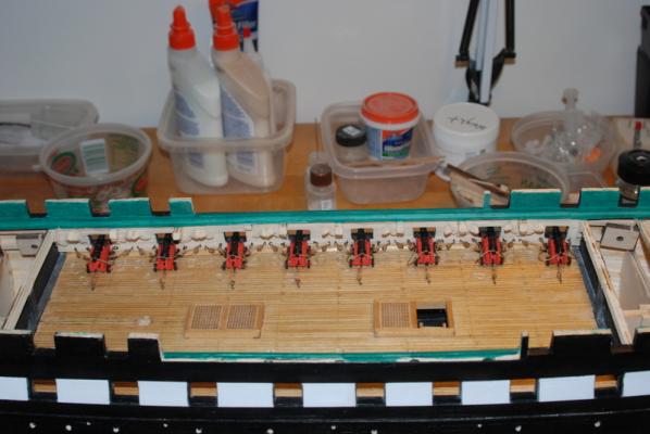
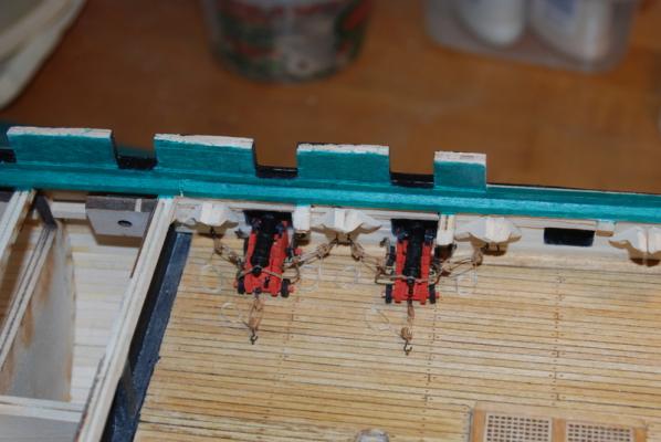
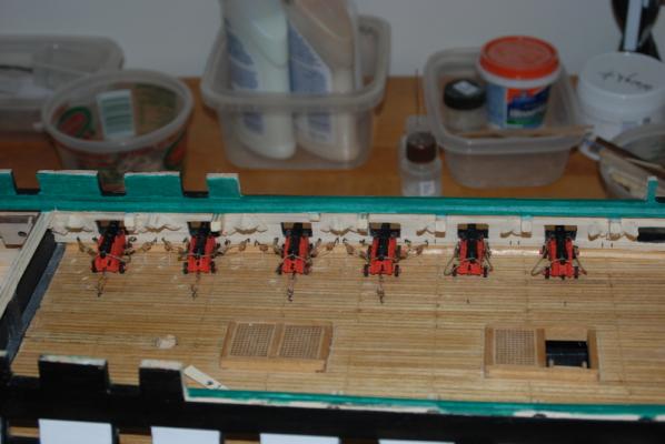
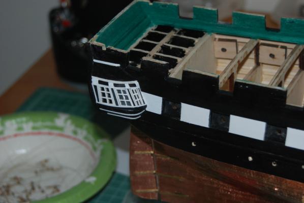
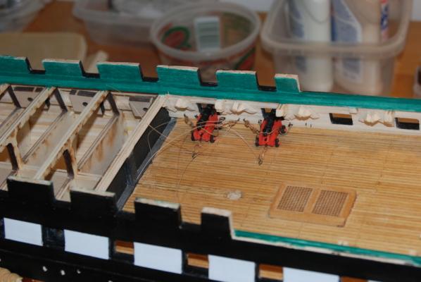
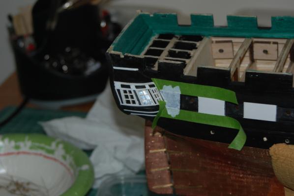
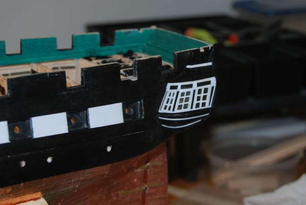
Thanks George. I can't wait for you to start either. Well. here is the white stripe terminated at the quarter galleries. I am glad you got me to do this. Assembling and rigging the gun deck cannons continues. Here are the first two, completed with rope coils. I made up this jig to make the flat rope coils. I wanted them more oval shaped than round, so I used some brass rod to get the shape. I make the coils so they are close to the top of the rods to make it easier to get them off. I am using Dullcote lacquer to fix the shape of the coils, which is mostly successful. The coils do hold the shape but it takes a small bit of CA to hold them together. These coils are only a couple of turns because I would think the tackle lines wouldn't be really long. And here is the present state. I still have to secure the breaching lines on the two right hand cannons and then add the tackles. It is too nice a day here to go back into the basement, so maybe later tonight I will get back to it.

- 1,354 replies
-
- 9
-
-
- constitution
- model shipways
- (and 1 more)
-
I can't wait Steve for your interpretation of the Connie. I am sure there will be some great surprises (in the good way) along the way.
- 625 replies
-
- 4
-
-
- bounty launch
- model shipways
- (and 1 more)
-
OK George, first thing I did last night was mask off the area behind the last gun ports for the white strip. Each side got a first coat. This was after I removed the masking tape on the starboard side for the pilaster extensions. Then it was back to those first two cannons for the gun deck. The girl got her first two teeth tonight. I glued the barrels and quoins to the carriages in the little jig I made, then added caps over the trunnions using black paper strips. I glued the guns into place using CA on the pins and white glue under the wheels. I am really happy how well those pins hold the guns in place, as I don't have to worry about them coming loose as I work around them. It is a little tricky getting them in place and flat to the deck, but some gentle bending of the pin gets the job done. Once in place, I drilled holes for the eye bolts on the ends of the breaching ropes and for eye bolts for the side and training tackles. The eye bolts on the breaching ropes were pretty hard to get into the holes, as they are short and wanted to twist in the tweezers. But after many attempts I was able to get them glued in. The other eye bolts were much easier to glue into place as they didn't have any line on them yet. I was then able to hook the tackles to these eye bolts and those on the carriages. This also took some practice as it was hard to keep enough tension on the tackle after the first hook was place while trying to get the second hook in place. Again, after a number of tries it got easier. Once the tackle was tightened the hooks stayed in place nicely. This is the first time I have made these tackles up before installing them and I found it much easier than trying to thread the tackle lines with the blocks already in place. I was also happy to see that I had enough distance between the blocks on the tackles, which was helped by adding the eye bolts towards the center of the area between the gun ports, which is how they are on the real ship today. I was also happy that the angle of the two barrels look about the same. Hopefully this will continue as I put the rest of them in place. I still have to figure out how I want to finish those tackle lines, but I have some ideas I want to try out first. Two down, 14 yet to go.

- 1,354 replies
-
- 10
-
-
- constitution
- model shipways
- (and 1 more)
-
Really nice job, Popeye. I'd say I am sad to see this build end, but I am dying to see what you have in store for those other ships waiting patiently for your return.
- 956 replies
-
- 3
-
-
- andrea gail
- trawler
- (and 1 more)
-
Nope, that is exactly what I needed to hear, George. I will be extending them now. I think I was being a bit lazy.
- 1,354 replies
-
- 2
-
-
- constitution
- model shipways
- (and 1 more)
-
Whoo Hooo! She be looking beauuuutiful! Congratulations. I love all those accessories you added.
- 625 replies
-
- 3
-
-
- bounty launch
- model shipways
- (and 1 more)
-
Looks like a great new start. Take your time and don't hesitate to ask questions as you go.
-
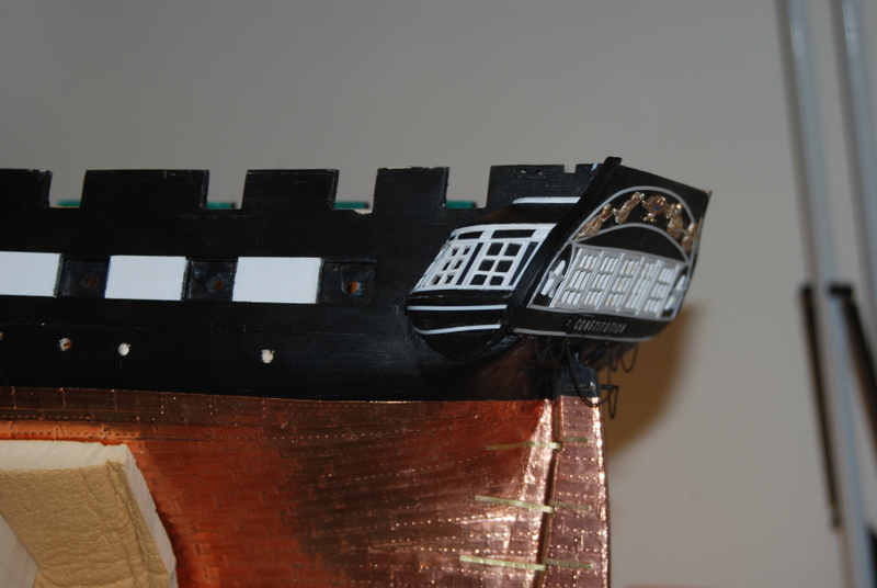
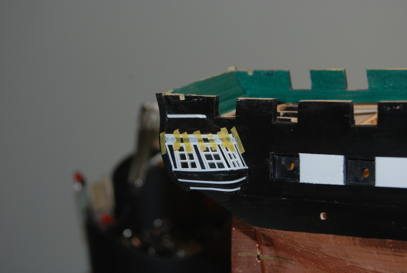
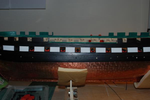
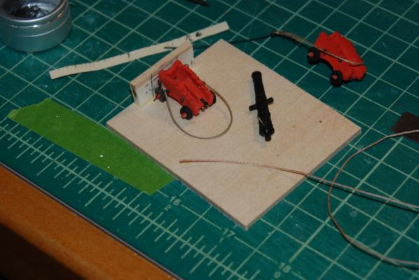
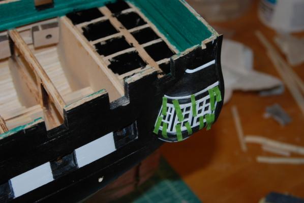
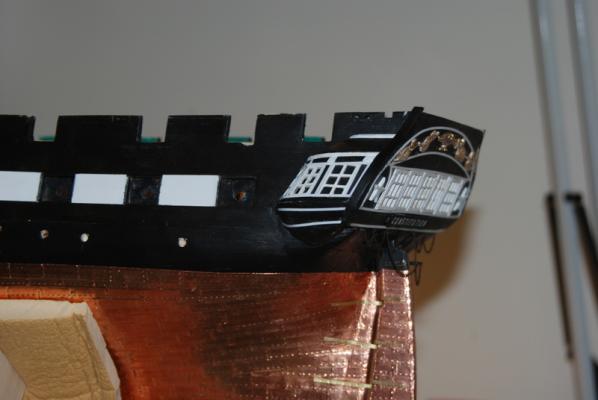
Thanks George and Tim, and the likes. I finished adding the styrene trim strips to both quarter galleries. I glued most of them with CA glue, using strips of masking tape to hold them, but about half the time the strip would come up when I removed the masking tape. I then switched to Hypo cement for these styrene strips, and what a difference. These stayed down after holding them for a few seconds, so no tape was needed. They seem much more secure too. I then used masking tape to extend the tops of the pilasters into the roof block and painted these areas white. I was going to use wood for these extensions but I did not like the way they were raised from the rest of the quarter gallery. Here is the completed port side QG: I also decided not to extend the white stripe on the side of the hull to the quarter galleries, so they will not extend past the last gun port. I would be open to other opinions on this point, though. Here is the starboard side, which I am still painting the pilaster extensions: While that paint is drying, I have started to rig the cannons on the gun deck. I first made a jig to help assemble each cannon before placing them on the gun deck. I have a piece of wood that is the height of the cannon at the gun port, so I can set each cannon up at the same angle. I also have a hole in the base that I can use to drill a hole underneath the carriage for a pin that will go into the deck for each one. I can also use it to judge the size of the breaching rope as I make them. I am using rope I made with the ME rope walk for the breaching lines, which is pretty easy to work with, except that it wants to unravel. I use CA on each end, which also helps me thread it through the ring bolts on the ends and on the carriages. I first seize a ring bolt to one end, then thread the other end through both ring bolts on the carriage, then seize another ring bolt to the other end. I then open up the strands in the middle and slip them over the cascabel of the barrel. I may be making these ropes a little too short, but I will see how they look after I install a couple on the gun deck. here is the jig with a couple of guns in the works: I only have 16 of these guns to rig, but working up against the walls of the gun deck will be interesting. I'll have updates of that as I go along.

- 1,354 replies
-
- 6
-
-
- constitution
- model shipways
- (and 1 more)
-
Amazing work Michael. Drilling those holes so precisely in something that you have already put so much work in would have scared me to death.
-
Steve, those supplies in the boat look awesome.
- 625 replies
-
- 3
-
-
- bounty launch
- model shipways
- (and 1 more)
-
That is a really cool way to display the Launch. Nice work.
- 425 replies
-
- 2
-
-
- bounty launch
- model shipways
- (and 1 more)
-
Great looking sacks and the bread is very realistic. Well done.
- 625 replies
-
- 3
-
-
- bounty launch
- model shipways
- (and 1 more)