usedtosail
-
Posts
2,424 -
Joined
-
Last visited
Content Type
Profiles
Forums
Gallery
Events
Everything posted by usedtosail
-
 Or is the rudder shipped but the tiller is unshipped? To me it looks like the top of the rudder is between the crane extensions, but the tiller is not there. Either way will work, though.
 -
mini drill chuck for those small drill bits
usedtosail replied to AON's topic in Modeling tools and Workshop Equipment
I use this one from Model Expo: http://www.modelexpo-online.com/product.asp?ITEMNO=EN409C It takes a bit of fiddling to get those small drill bits centered in the chuck, but after that it works pretty well. -
Your rigging really looks great, Bill
-
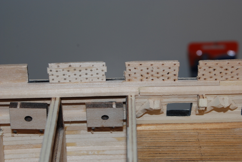
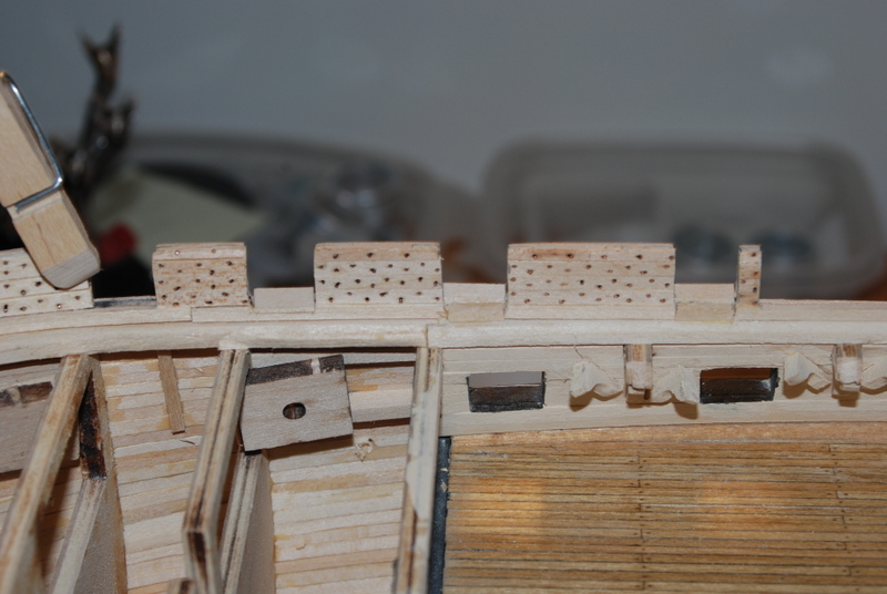
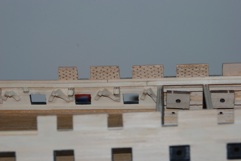
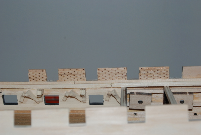
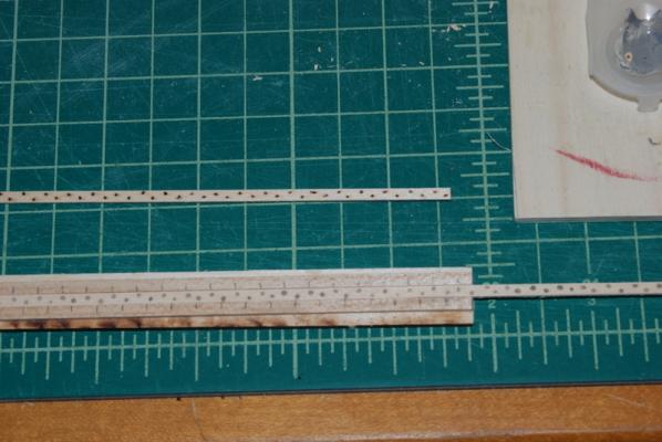
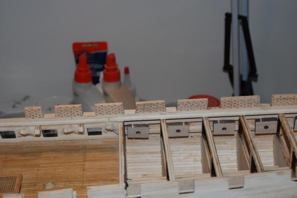
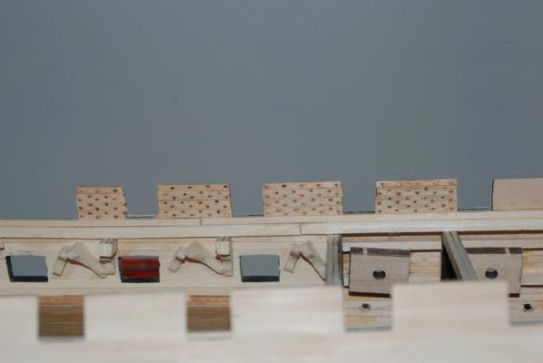
Here I go redoing things again. First of all I did make up a rectangular sanding stick with some medium sand paper and cleaned up the bottoms of the spar deck gun ports somewhat, so they are looking better. Yesterday, I came across a Constitution build log on this site by galf, where he used WHITE GLUE for the rivet heads on the inner bulwarks. Now, if you remember my first thought was to use CA for these which I tried with no success. All the time I was doing that experiment, the white glue was sitting right next to the CA glue bottles, and I never thought to try it! Doh! Last night I took a wood strip and added dots of white glue to it using a toothpick. They looked nice and round and did not stick up too much from the plank, which was just what I had envisioned when thinking of using the CA. When the glue dried, though, the dots disappeared since they turned clear, but after giving the strip a quick coat of paint, there they were in all there round glory. So here I got crazy and pried off half of the wire riveted strips on the port bulwark sections, then I made up two long strips using the white glue method. I did add some grey paint to the white glue before I did this, so that the rivet heads would be visible after they dried, so I could line up the pattern when installing the strips. I cut sections from the long strips and replanked the bulwark sections that I removed, and I really like the results better than the wired method. Here you can see a comparison of the old strip (above) with the new (In the jig) and the greyed white glue and toothpick that I used. And a closer view of the strips: And here is a comparison on the model, with the new strips on the left section and the old on the right sections: It took a little while to get the hang of this and get the dots somewhat consistent. After a while, the glue got too tacky and was not sticking to the strip well, so I made up a new batch of grey glue, which made more consistent dots. Another nice feature of this method is that I can add or touch up dots on the planks after they are installed, like I did for a few that were too small. After I took these pictures, I pried off the rest of the old planks on the port side and replaced them with these new planks. It went very quickly the second time, as did making the strips. Next week I replace the strips on the transom and starboard sides.


- 1,354 replies
-
- 10
-

-
- constitution
- model shipways
- (and 1 more)
-
USS Constitution by galf
usedtosail replied to galf's topic in - Kit build logs for subjects built from 1751 - 1800
Galf, just found your build log. Your Connie looks great. I tried CA glue for the rivets but not wood glue. I ended up using copper wire, but I really like the look of yours. Your copper job looks great too. I am getting close to that task. -
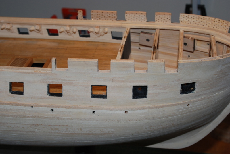
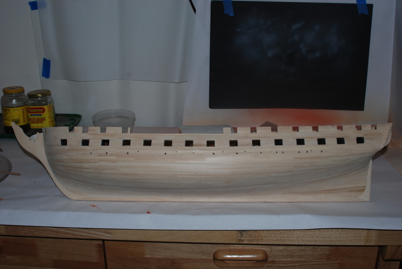
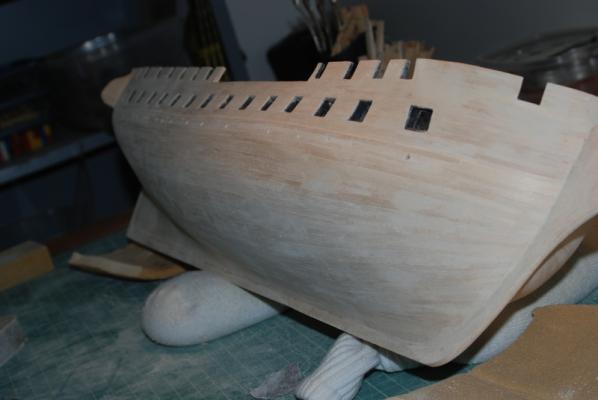
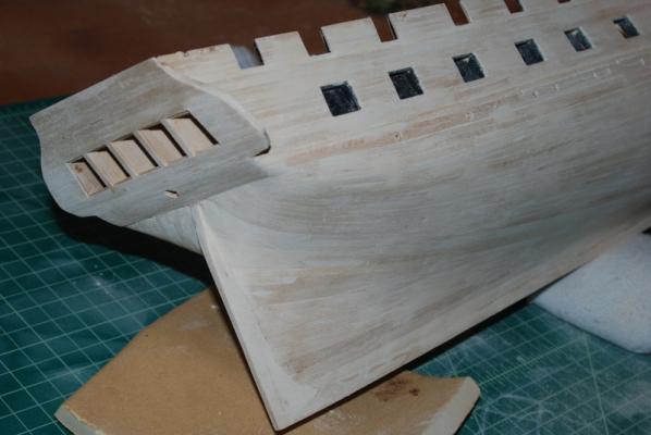
Thanks Patrick, although it is an idea that came from watching others on this site like EdT, with much less precision than his approach. And thanks for the likes too. Well, I am pretty happy with the repairs to the starboard gun ports and plank sheer. Here are the results from the outside and the inside: I am not totally happy with the squareness of the bottoms of the gun ports, so I will square them up a bit more with a rectangular sanding stick. I continue planking the inner bulwarks on the port side. Just a few more sections to plank then I have to clean up the gun ports on this side. I will be doing that much more carefully so I don't have to repair them too.

- 1,354 replies
-
- 10
-
-
- constitution
- model shipways
- (and 1 more)
-
Thanks Michel for the video. I am still not sure how it works, but you can' t beat visual evidence. Your machining of this engine is fascinating to me.
-
This is a really nice rebuild, Cristiano. Your research methods and sculpting ability are outstanding.
-
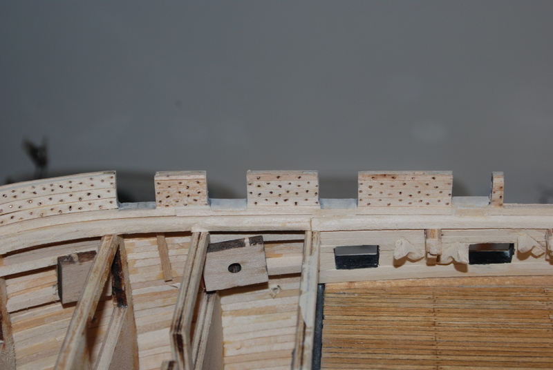
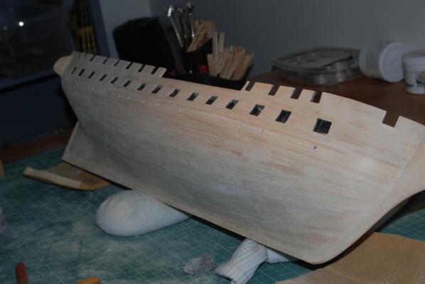
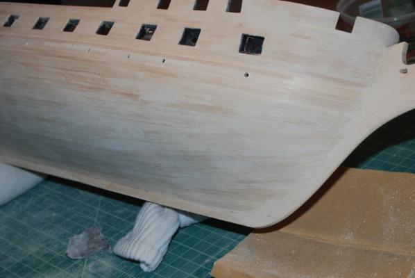
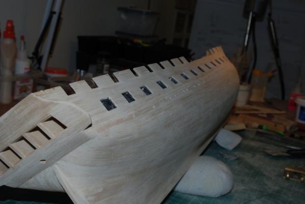
Well, another major milestone, but not a good one. A major foul up, and when I say foul I mean something else. I was so happy to finish the inner bulwark planking on one side that I had to sand the sides flush with the gun port sides. They looked great from the inside. But then I had to go and turn the ship around. While sanding the sides of the planks I had also managed to sand some of the planking below the corners of the gun ports. Oh, I thought, I'll just sand these out if I can. Well, they sanded out but then when I looked back inside the bulwarks, I had sanded the plank sheer down under some of the gun ports, one so much it was half gone. At first I thought I would have to replace the plank sheer, but that would have been too disruptive. So on the worst one I cut out only the portion of the plank sheer under the gun port and replaced it with a new piece of the same wood I used to make the original plank sheer. I will fill in the joints with wood filler, so this should look OK when painted. Here you can see the damage under the gun port on the left and the cut out plank sheer under the gun port on the right: I then realized I would still need to add a thin strip on the bottom of the gun port to make up the other material that was sanded away, which I did. Then I realized that I could just file the other damaged plank sheer sections square, and add a wider strip of wood over the bottom of the gun port and the plank sheer, which is what I did for the rest. Here you can see the two types of repairs: They are all drying now so the next steps will be to sand these down (much more carefully) and fill the cracks with wood filler to try to make everything look like one piece. We shall see how this turns out.

- 1,354 replies
-
- 9
-
-
- constitution
- model shipways
- (and 1 more)
-
Chuck, that planking looks great. And thank you for the drop plank lesson. When I was planking the MS Constitution the drop planks just didn't seem right, as I had to edge bend the "tail" to fit the previous plank. I see that you tapered the previous plank at the end to prevent this. Next time I will know to do it right. Thanks again. Also, the MS Constitution instructions and plans show to taper the wale planks at the stem.
- 1,051 replies
-
- 1
-
-
- cheerful
- Syren Ship Model Company
- (and 1 more)
-
HALF MOON by jct - FINISHED - Corel
usedtosail replied to jct's topic in - Kit build logs for subjects built from 1501 - 1750
J, i like that cardboard method for the deadeyes. I will be remembering that one. The shrouds look great. -
Nice work on the rigging Bill. I am impressed with your speed, especially the rat lines. They look great.
-
You got it Captain. Take all you want. I'm flattered.
- 1,354 replies
-
- 3
-
-
- constitution
- model shipways
- (and 1 more)
-
Tim, I don't mind at all. That is what I love about this site. A year ago I would have had no idea how to tackle something like this.
- 1,354 replies
-
- 2
-
-
- constitution
- model shipways
- (and 1 more)
-
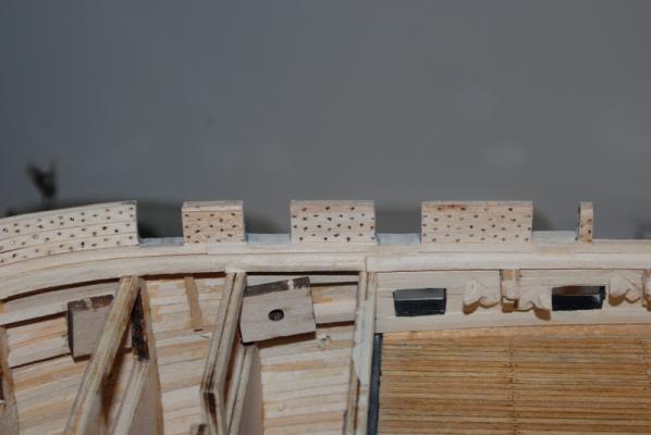
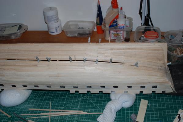
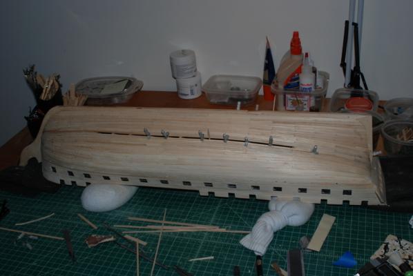
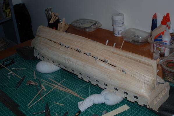
Well, here are the results. I planked a few sections of the inner bulwarks with the riveted planks. I still need to trim the ends to be flush with the gun ports. Not as precise as I have seen other modellers create these rivets, but I think the overall effect is what I was after. It will be a while before they are painted, so I am curious to see what they will look like then.

- 1,354 replies
-
- 6
-
-
- constitution
- model shipways
- (and 1 more)
-
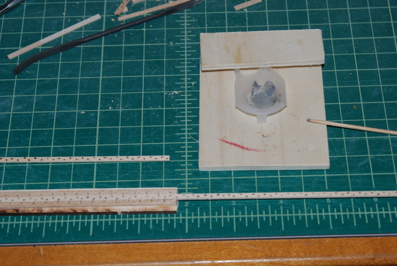
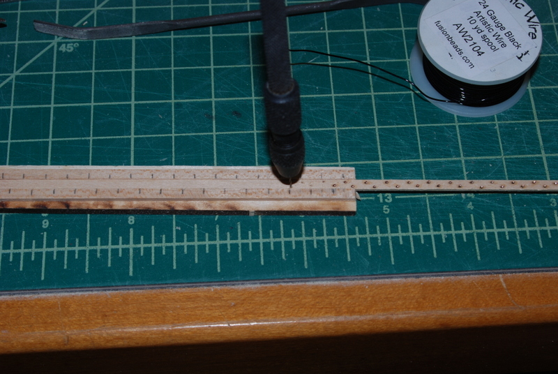
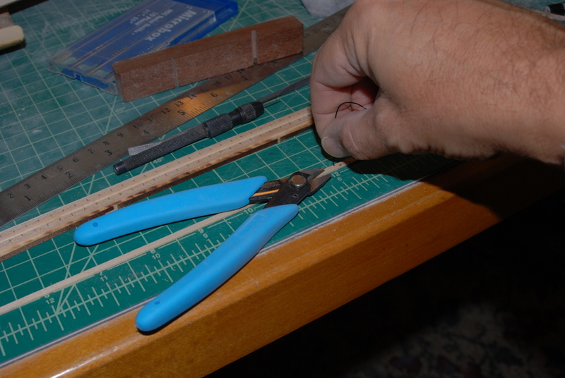
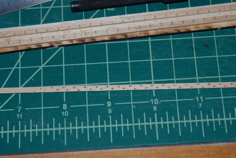
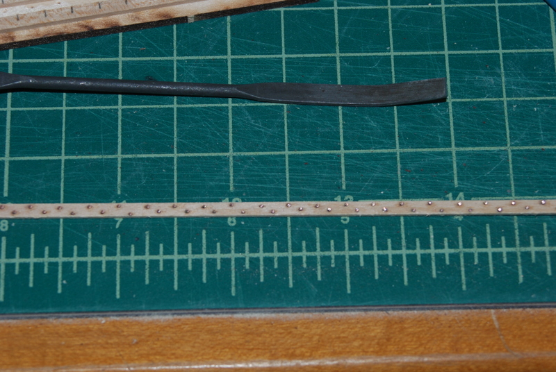
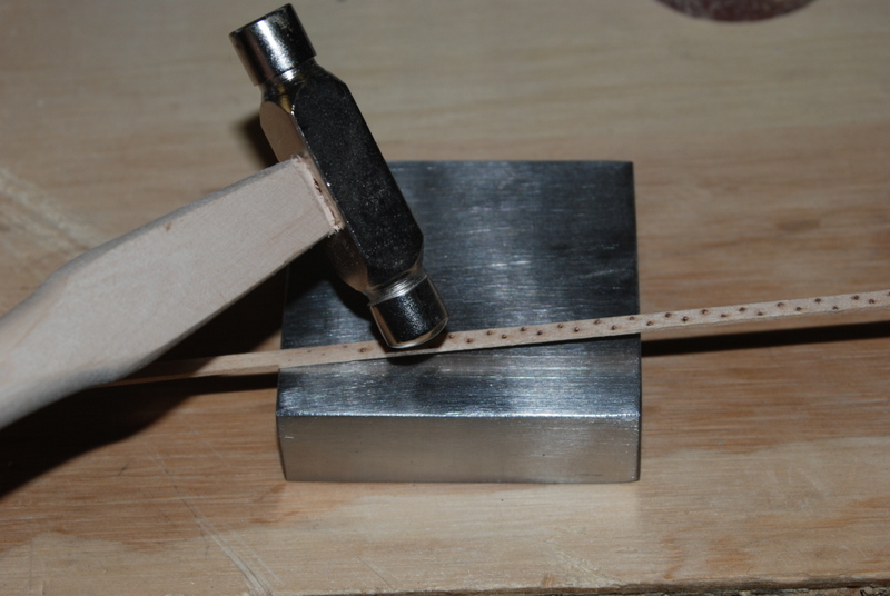
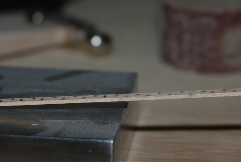
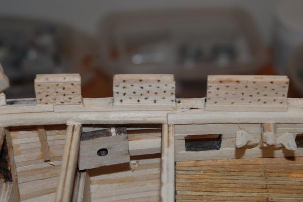
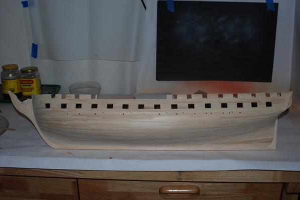
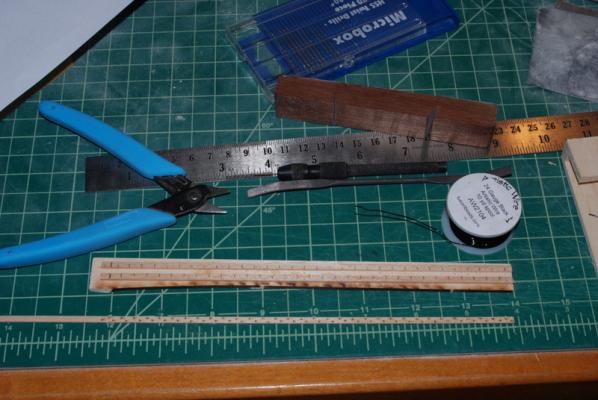
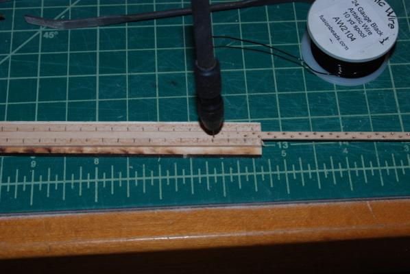
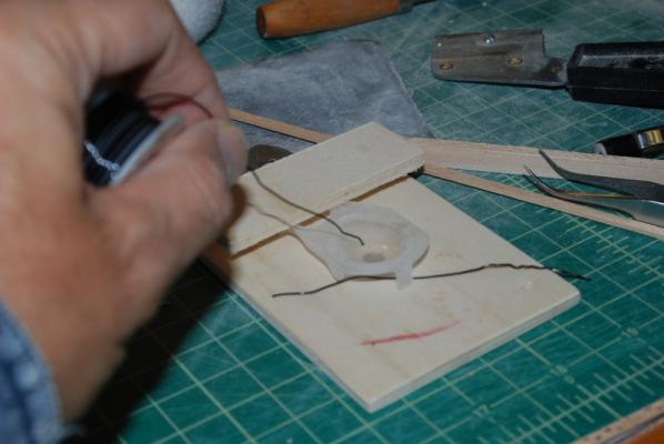
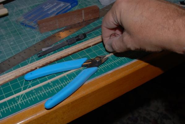
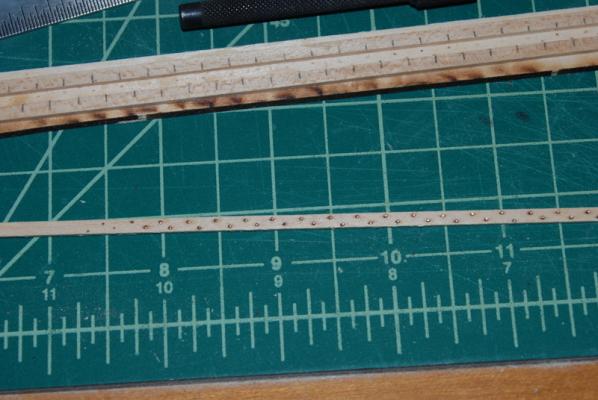
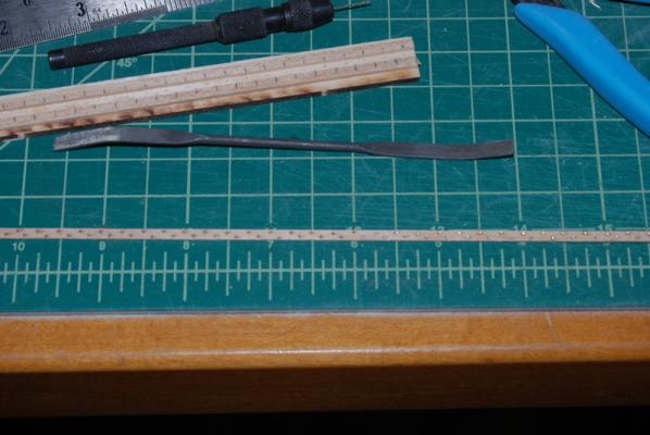
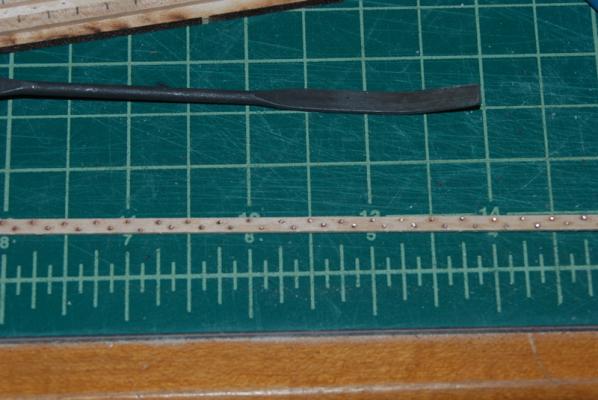
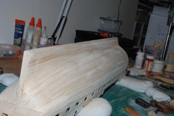
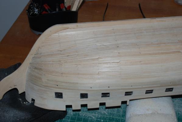
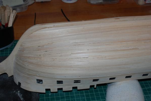
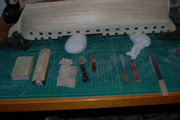
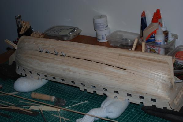
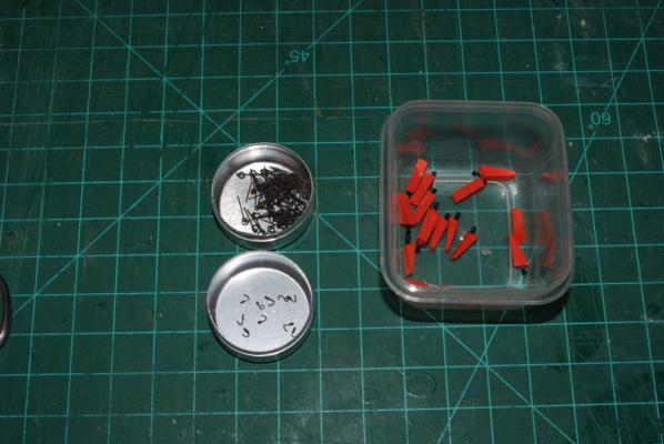
Thanks all. After a fine Thanksgiving break I am back to work. I am excited to have the hull planking finished, at least for now. I did some more work on the wales to get them as smooth as the rest of the hull, so here it is after a medium and fine sanding of the whole hull. Scott - I hope I didn't make it too smooth. I know when I prime it, I will find that I have more blemishes to fill and sand out. Now it is on to more interesting work. Planking the inside bulwarks is the next task, with all those rivets to show. My original thought was to try using small drops of CA glue to simulate the rivets, like I have done on pintels and gudgeons in the past. This works fine on metal, but on wood the CA just soaked into the wood. OK, I thought, how about if I put some wipe on poly on the wood first. This slowed the soaking down, but eventually I had the same result. Time to come up with a new method. I had seen other builds where they bought individual rivets from a model railroad company, but when I priced these out they seemed a bit expensive. So, I came up with my own way to make rivets. I drilled some holes in a strip of wood, dipped the end of a wire into CA, then pushed it into the hole. I cut the wire off and repeated in the next hole. The wire was sticking up a bit, so I trimmed it flusher to the wood, then used a ball peen hammer to gently tap the ends down, which also mushroomed the wire just enough. I was happy with the look and the process wasn't too bad, so I made up a jig to help. Here is the story in pictures: First, here are the tools I used for this. That cutter does a good job but does not cut the wire completely flush, which worked out to be a good thing. You can see the jig I made up, which is just two strips of wood with offset markings to show where to drill the holes for the rivets. I am drilling two rows per strip, offset by half the distance between rivets, which is the pattern on the current ship. I am not yet sure if I can fit two rivets at the end of each strip, but I may try that. Most of the strips go between the gun ports, so they will be short. Here I have a planking strip in the jig and am drilling the holes. On my first attempt, I glued the wire into the holes with the strip still on the jig, but when I pulled the strip off a few of the wires stayed glued into the jig. I now drill the holes then take the strip out of the jig before gluing in the wires. I dip the end of the wire in a small puddle of medium CA. You can see my patented CA glue holder using small cups from my daughters contact lenses. I have a lifetime supply of these. Then I push the wire into a hole and cut it off with the cutters. I can get into a pretty good rhythm this way. After I fill a bunch of holes, I go back and trim the wires again to get them closer to the wood and here is how they look at this stage. I then use the file shown to gently file them down a little bit more and brighten the ends. At first I was going to use them like this, but after sleeping on it, I decided they were too sharp and still too high, so the next day I found this ball peen hammer and tried tapping them to see if they would flatten out a bit. I used this jewelers block that I had to keep the wires from pushing through the back of the strip. And here you can see the final result on the right, the wires on the left have not been tapped down yet. I was a bit worried that the tapping would flatten the wood out too much, but you can see from the side that the wood is still in pretty good shape. I will cut out a few strips and see how they look on the bulwarks tonight, but I think they will look good. Its a bit of work but not too bad, relative to all the other work that still needs to be done. This is such a prominent detail that I don't mind taking the time to make these strips. I don't yet know how to handle the curved planks at the bow. I think I will have to bend them to shape before adding the rivets, then add the rivets before gluing them to the bow. I think trying to bend the plank with all those holes would just break it. I am also in the process of designing a cradle for the model but that is a story for another day. I did measure the contour of the hull in the two places that the cradle will support, since this seemed like a good time for that before I start coppering the hull.


- 1,354 replies
-
- 11
-
-
- constitution
- model shipways
- (and 1 more)
-
I had to add wood on the insides of some of the bulwark extensions to fix these errors. I checked each of the bulkheads for symmetry before I added them to the keel and marked the areas that needed to be removed/added to. My bulwark extensions are not as high as the kit plans, however, since I am only building to the top of the main rail, since that is closer to the 1812 version.
-
Looks good to me, Rich.
-
Cutty Sark by NenadM
usedtosail replied to NenadM's topic in - Build logs for subjects built 1851 - 1900
Really nice work, Nenad. Thanks for the tutorial.- 4,152 replies
-
- 1
-
-
- cutty sark
- tehnodidakta
- (and 1 more)
-
I just spent two days reading through your log Jon. You are doing fantastically for your first time build. I have learned a few things from the way you have approached some of the more challenging aspects of the build. I look forward to following along with the rest of it.
-
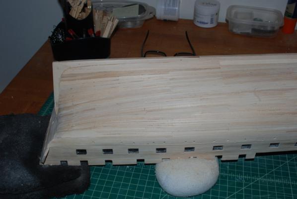
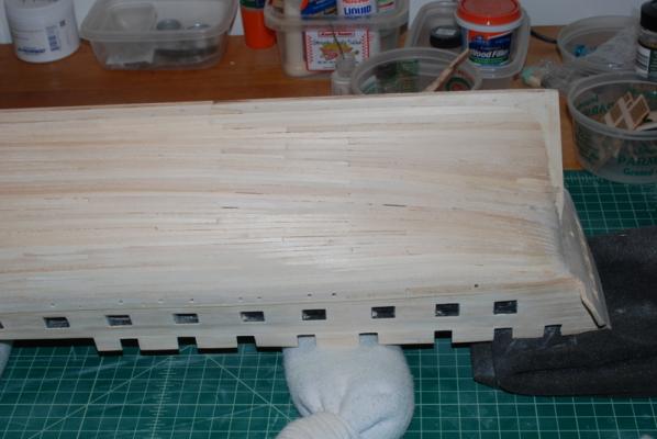
Thanks Tim, George, Scott, and Warren, and the likes. Scott - thanks for that reminder to not sand too much. I have had this problem in the past, especially where I had bad clinkering going on. I think filling the low spots with wood filler helps in this regard, as I can see how much is coming off as I sand it out, without trying to remove all the surrounding wood. I spent a couple of hours last night getting the rough sanding done. I had a ridge along both sides where the hull planking met the bottom of the wales, but after some serious attention with the sanding block I was able to get this area to flow together. Here are some shots of the hull at this point, ready for the medium and fine sanding, which will have to wait until Sunday, after the holiday. Happy Thanksgiving to all of you who celebrate it, and a nice weekend to the rest of you. PS - after looking at the pictures in the preview pane, I think there may be a few spots that still need some filler, which I will address as I do the rest of the sanding.
- 1,354 replies
-
- 14
-
-
- constitution
- model shipways
- (and 1 more)
-
That is a very fine boat, Bob.
-
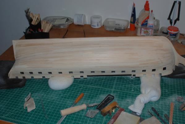
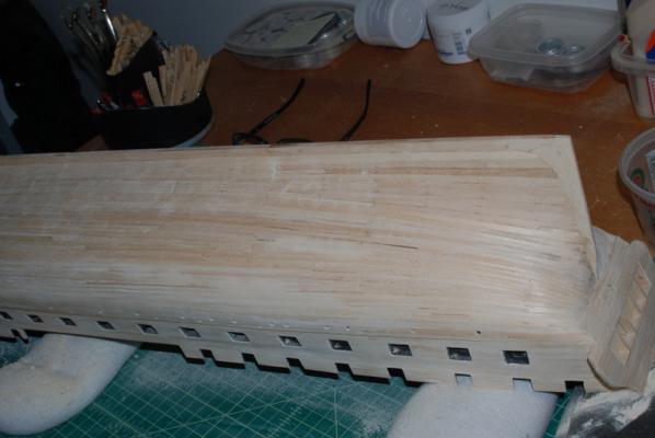
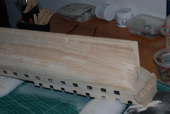
Thanks again guys. The encouragement is really appreciated. Well, after 11 months of working on the hull, a major milestone has been reached - all of the outer hull planking is on. I spent this weekend sanding and scraping the hull, adding wood filler where needed, and sanding and scraping some more. I am still only using rough sand paper, so there is still a lot of work to be done. Here is a picture of the various tools I am using to get the planks smoothed down. The curved end of the large sanding block has really come in handy on the curved parts of the hull, especially in the stern. The handle with the straight razor blade I use as a scraper. That little block plane come in handy with planks that are raised from the rest. Here are some shots of the rough planking before I started sanding: And here are some shots during the sanding process: These two shots are after some sanding but before any wood filler was added. You can see some of the gaps that have to be filled. I am not sure how long it is going to take me to get to the point where I can start sanding with finer paper, but probably later this week. It always amazes me how much better this looks after some wood filler and a preliminary sanding. But, then it seems to take just as long or longer to get to a finished hull, if there is such a thing. As I said before, I always find areas that could use more work and I don't expect this hull to be any different.
- 1,354 replies
-
- 8
-
-
- constitution
- model shipways
- (and 1 more)
-
Thanks again guys for the encouragement. I am feeling a bit better about the state of the planking now that it is almost done. I am down to one plank section per side, which I should be able to finish up tonight. Those screw in planking clamps have worked really well on these small gaps. I bought a bunch of them a few years ago when Micro Mark had them on sale, so I didn't run out once on this build. They were a bit expensive even on sale, but they sure came in handy. There were even a few planks where I did not have a gap left that I just screwed the post through the plank to hold it, which I will fill the hole with putty now. I first tried straight pins, but they would not hold the planks flat to the filler blocks. I am seeing some wavy-ness when looking down the hull, but I think that will be sanded out when I complete the sanding. That is going to be the next big task, one in which I always have a hard time. I think that I am getting close to being done, then look at the hull with light from a different angle and see all sorts of anomalies. And this hull is bigger by a lot than any previous planking that I have done. So, I just need to get at it and take my time and be generous with the wood putty (although most of it will get sanded off). Since I am down to working one plank per side at a time, I have had some time to make all the quoins for the gun deck cannons. I also made all the ring bolts for them, which I have blackened along with the eye bolts for them. I have started making the hooks for the gun tackles, as well. I can do about 10 per night before my eyes give out, and I need about 90 of them. I started out trying to use a pair of pliers with round ends for the loops, but ended up using tweezers instead, which resulted in smaller loops. The hook part is made by bending around the end of a needle nose pliers. I do this all with the wire still on the roll, then cut off the hook and file the end somewhat pointy, although not as pointy as I would like yet. It is really hard to hold them still while filing, since they are so small. I will post pictures of the sanding as it progresses.
- 1,354 replies
-
- 8
-
-
- constitution
- model shipways
- (and 1 more)
-
Very nice Bob. Those sails really do her justice. You and the admiral both must be very happy.