usedtosail
-
Posts
2,421 -
Joined
-
Last visited
Content Type
Profiles
Forums
Gallery
Events
Everything posted by usedtosail
-
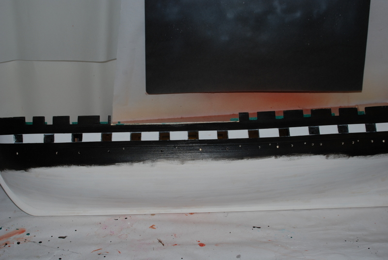
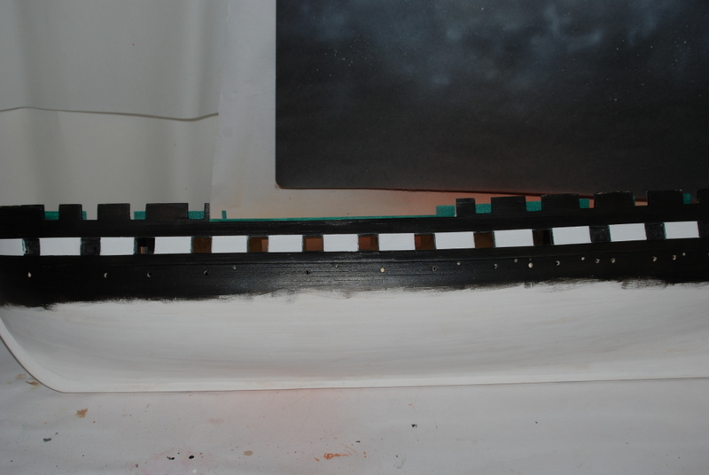
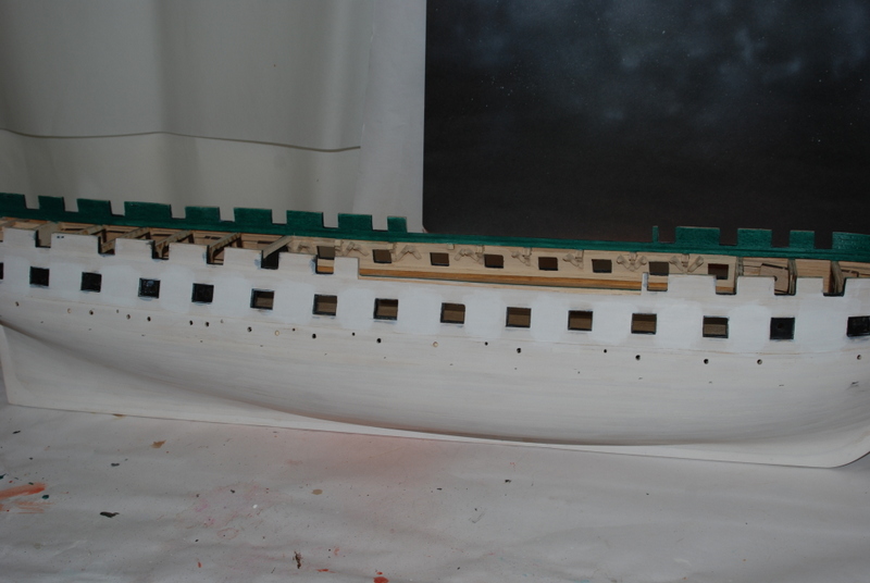
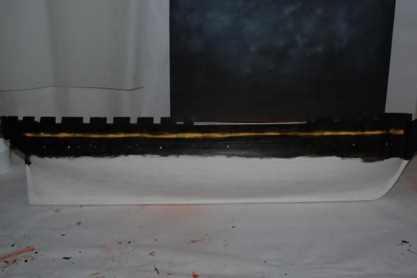
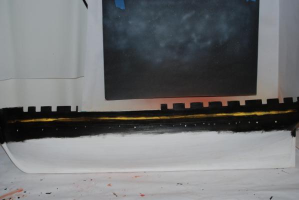
 Thanks again Patrick. Are you a Browns fan? That is a tough division for them. Well, I ended up giving the hull one more coat of black paint: I decided to stop here, so off came the masking tape. Here is how it looked right after I removed the tape: There were just a few small bleeds of the black into the white stripe, which I was able to touch up with some white paint. The areas around the tops and bottoms of the gun ports needed some touch up with black paint. Here is how it looks now after that: Maybe a little more touch ups inside the gun ports yet, but it is getting close. I also still need to touch up the black inside the stern.
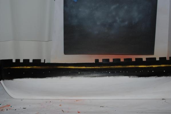


- 1,354 replies
-
- 12
-

-
- constitution
- model shipways
- (and 1 more)
-
HALF MOON by jct - FINISHED - Corel
usedtosail replied to jct's topic in - Kit build logs for subjects built from 1501 - 1750
That is a great case. The Half Moon looks wonderful inside it, too. -
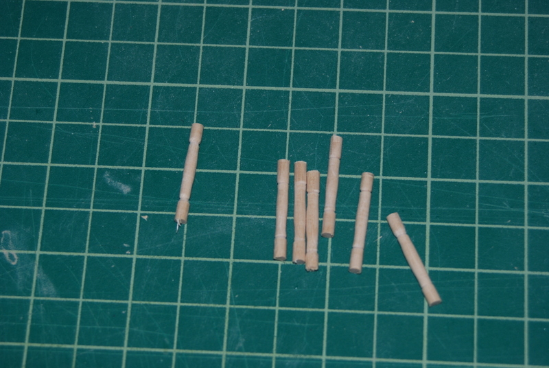
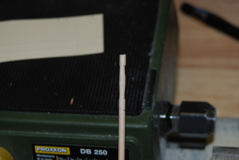
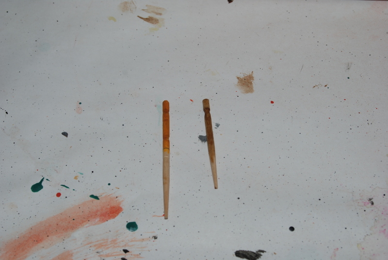
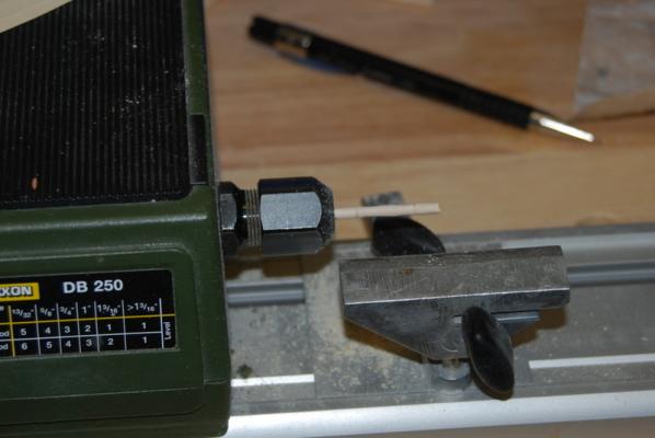
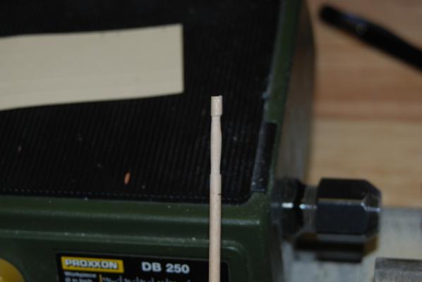
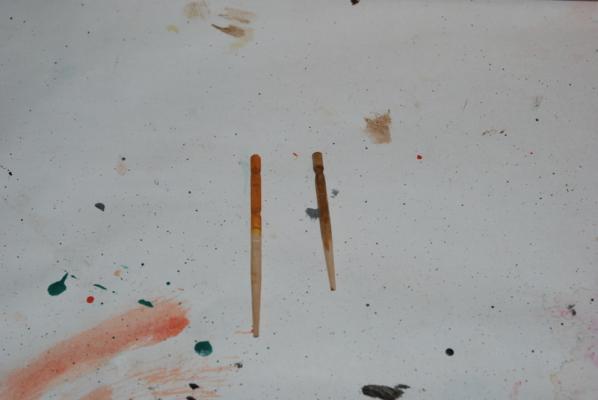
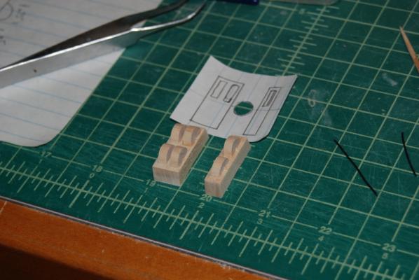
Here is the process I used to build the stanchions for the gun deck. I calculated the size of the center section and made the end sections a bit long, so I can trim them down at each beam as I install them. I am using a small Proxxon lathe for shaping these, with a couple of small turning chisels and sand paper. Getting them consistent took a few tries but after the first two it went easier. This one looks a little lop sided but I made a bunch and will choose the best ones, or hide some of the worst ones in the back. I was going to stain these with oak stain, but the trial didn't look very good (right). I then tried some burnt sienna paint with an overcoat of yellow and it is getting closer (left). I will most likely end up with a mixture of burnt sienna and yellow for the final color.

- 1,354 replies
-
- 6
-
-
- constitution
- model shipways
- (and 1 more)
-
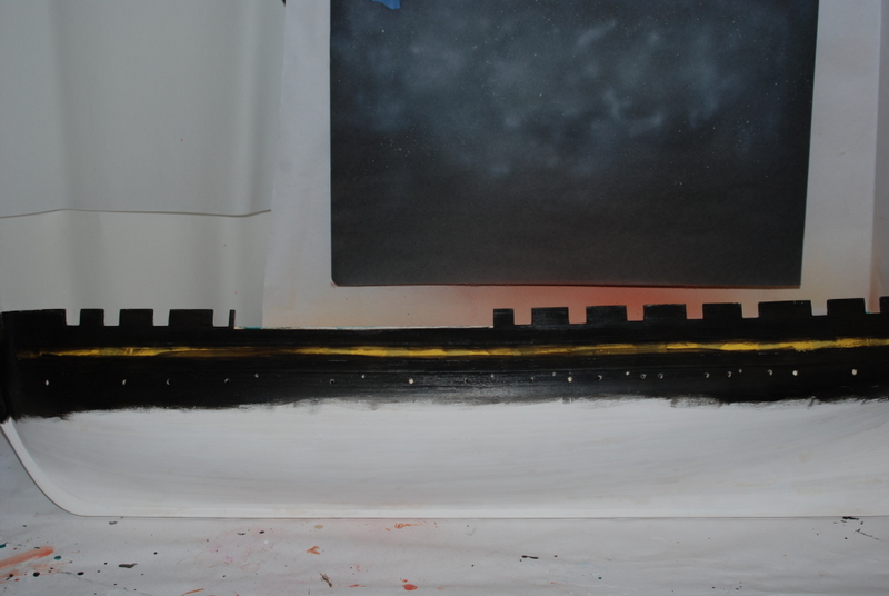
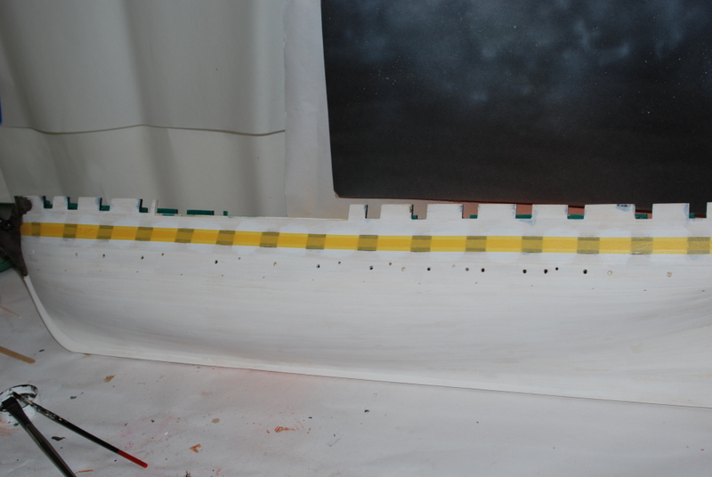
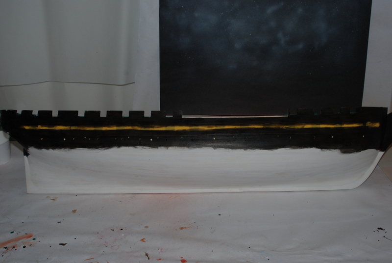
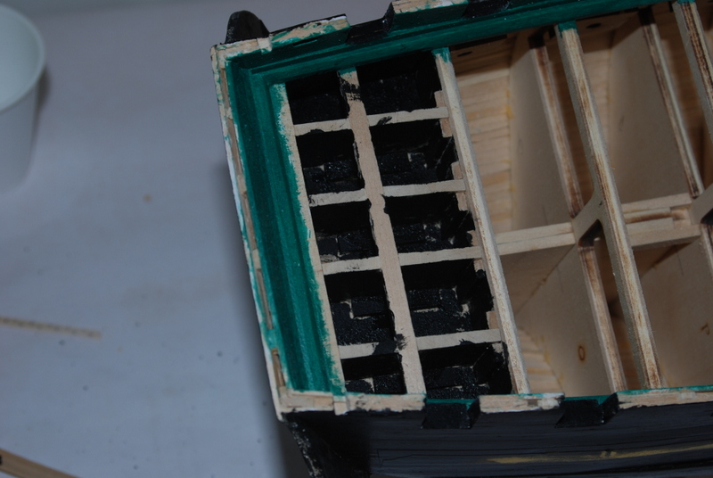
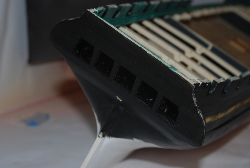
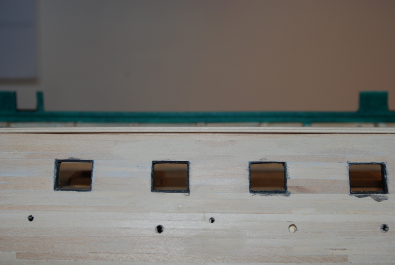
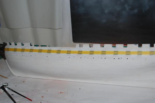
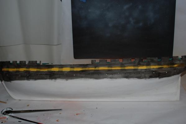
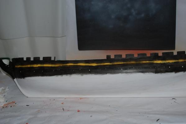
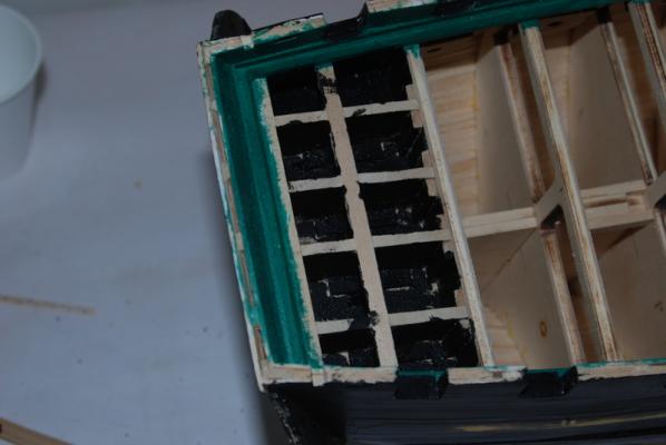
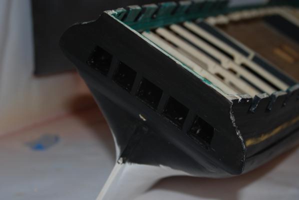
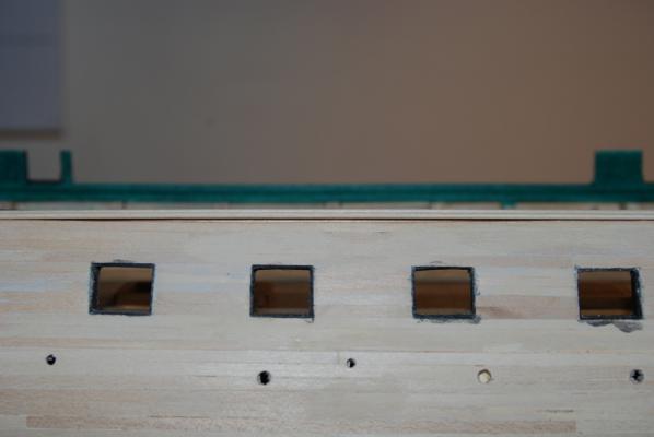
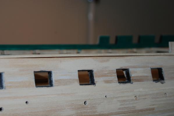
Painting the outer hull continues. I masked off the area for the white stripe between the gun deck gun ports: I burnished the edges of the masking tape to hopefully avoid any running of the black paint, but we won't know how successful I was for a while. I then have been painting many coats of thin black paint. I decided to take pictures between each coat so you can see how the painting progresses. First coat: Second: Third: Fourth: It is getting close but not there yet. Probably one or two more. I have also been painting the transom. In order to be able to use clear acetate for the windows, I painted inside the hull framing at the stern black, so this wood would not show through the windows: The view from the stern: Still needs some touch up inside the window frames. In between coats of paint, I have been building the stanchions for the gun deck. I show this in the next post. Oh, and by the way - GO PATRIOTS!
- 1,354 replies
-
- 6
-
-
- constitution
- model shipways
- (and 1 more)
-
That looks terrific, Tuffarts. May I call you Tuffs?
-
A pin helps hold the yard in place while you are threading the harness and other lines. I found it to be a big help.
- 1,756 replies
-
- 2
-
-
- constitution
- constructo
- (and 1 more)
-
Need a realistic belaying plan for the USS Constitution
usedtosail replied to Modeler12's topic in Masting, rigging and sails
Yep, Bill, now I remember it came from the NRG Shop Notes. I have not yet compared it to the AOS or MS plans, but I am sure my rigging will be some combination of all three. On previous models I have made up my own belaying plans based off the supplied plans and what made sense to me, and I will be doing the same with this one. It also will depend on how many belaying pins can be fit on the pin rails and still are functional and look good - ie not too crowded. -
Thanks Tim. Jay - Thanks for the advice. I have had pin rails come up on previous models while rigging, so I always pin them to the deck now. As for the gun deck, this is the same Model Shipways kit that you built. I just chopped up the tops of the bulkheads and added the gun deck planking, so I am kit bashing the MS kit. The hatch on the spar deck will be open, not closed with grates, and the boat will sit on deck beams across that opening. This is more like the ship's configuration in the early 1800's. The process I used to add the portion of the gun deck is documented earlier in this build log. I bought the cannons separately for the gun deck, as they will have carriages and not just dummy barrels.
- 1,354 replies
-
- 2
-
-
- constitution
- model shipways
- (and 1 more)
-
Need a realistic belaying plan for the USS Constitution
usedtosail replied to Modeler12's topic in Masting, rigging and sails
I have this one but not sure where it came from: Does it help?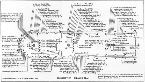
-
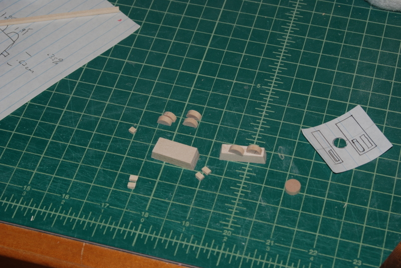
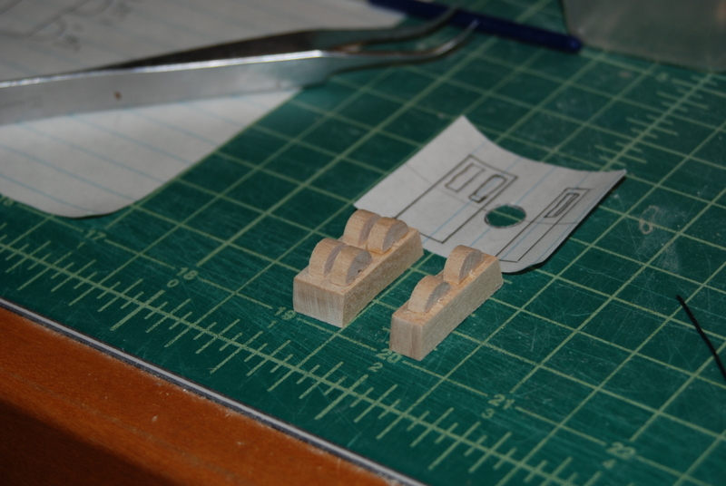
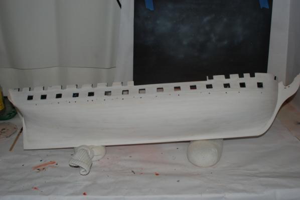
Snow day today so got to work at home. A quick update... I finished priming the top sides of the hull. and gave the stripe areas three coats of white paint. In between coats of primer, I have been making the two chain pump housings for the gun deck. Tim I, I found your build log from the cross section and you had a nice sequence for making the chain pumps, so I used it along with the plans in the AOS book. I will paint these brown and make up the wire handles, then put them aside until I can install them. Tonight I will mask off the white stripe and start painting the topsides black. I have already marked off the top of the copper plate line, which I will overlap some with the black, to get a good line at the top of the copper plates.


- 1,354 replies
-
- 10
-
-
- constitution
- model shipways
- (and 1 more)
-
Looks great Bill. You are a real inspiration for us Connie builders.
- 335 replies
-
- 4
-
-
- Constitution
- Mamoli
- (and 3 more)
-
Captain Al, The way I have made square holes in a model is to drill a round hole, then use the tip of a large nail, which is cut in four faces, to press into the round holes, forming a square hole of sorts.
-
Captain, I have tried leaving them on as a strip, but had trouble keeping the offsets looking right from one row to the next. With the individual plates, I can compensate a little with each plate. Bill, yes this is the same copper tape as the stain glass folks use. It is what Model Expo supplies with the kit. I have used this in the past and as long as the hull is well prepared and the strips are burnished as they are placed, they hold extremely well with just the adhesive on the back. I prime the hull under the plates to get a nice smooth surface for the plates, and use a popcycle stick that I filed to an angle to burnish the plates down with. This will be a little more challenging on this one because I don't want to burnish the nail heads away, so I have to be a bit more careful during that process. I have used this method on almost all my models and the tape is still stuck after 8 years. How archival this is I don't know, but I am not too worried about that. It would be interesting to hear if anyone has had problems over the long run with the tape as is.
- 1,354 replies
-
- 3
-
-
- constitution
- model shipways
- (and 1 more)
-
Thanks Captain. Yes, I take a strip of tape and score the individual plates but don't cut through the backing. Then I peel them off the backing as I apply them to the hull. This makes it much easier to get the backing off then if you cut them into individual plates first.
- 1,354 replies
-
- 1
-
-
- constitution
- model shipways
- (and 1 more)
-
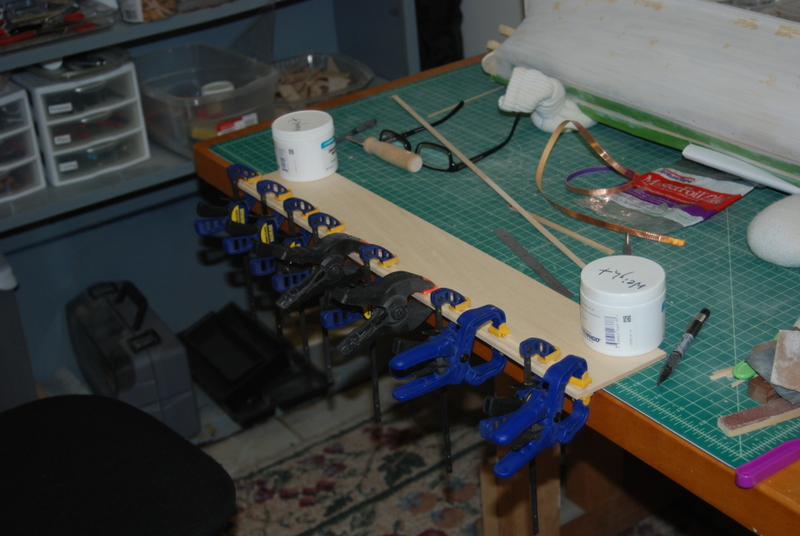
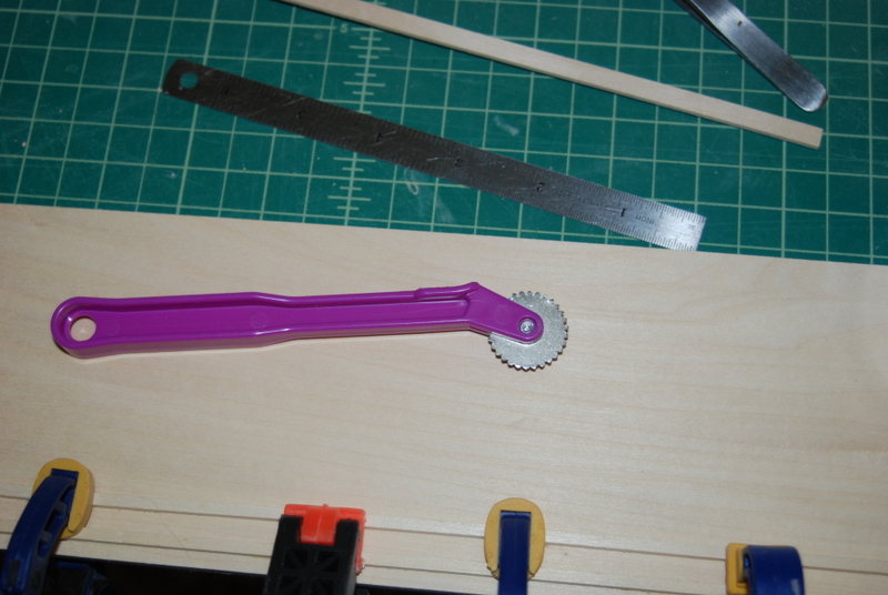
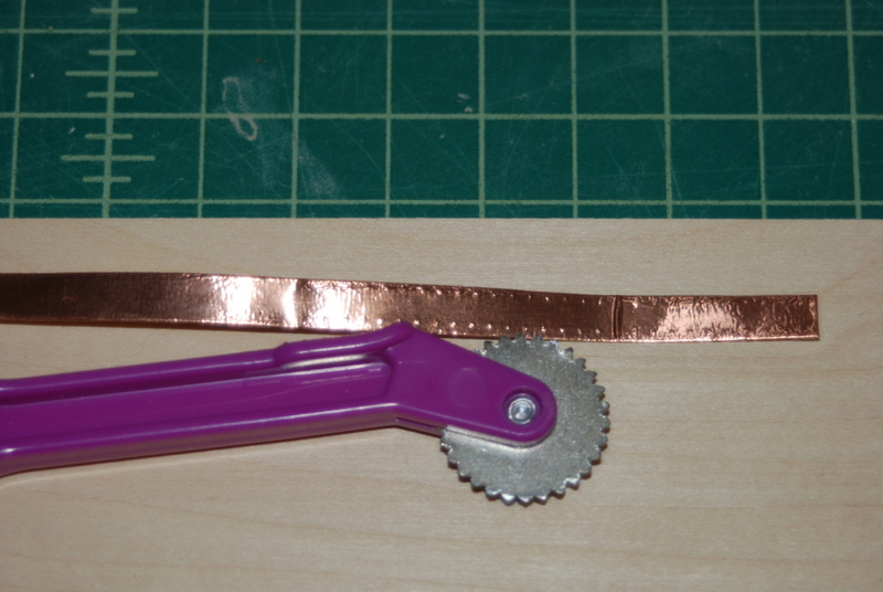
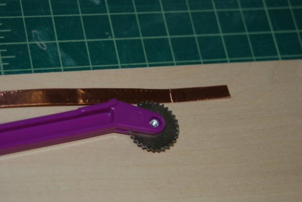
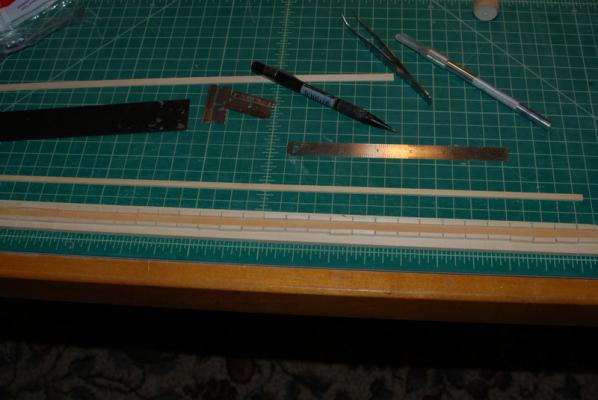
I gave the hull a few coats of gesso as a primer. I masked off the gun port openings and tried airbrushing this on, but was having too much trouble getting the right consistency, so I brushed on three coats of thinned gesso, sanded the hull down with fine sandpaper, then filled in a few more spots that showed up with the primer. I cleaned up the hull and gave it one more coat of the thinned gesso. The thinned coats smoothed out nicely, so I am pleased with the brushing. I did order a new airbrush that should handle larger areas better, so I will try that with the black paint for the top sides. I am also going to get some nicer brushes. I have a few large ones but they are not as high quality as the smaller brushes I have. I already know I will have to do some brush painting on the topsides, especially around the gun ports, so if I end up doing it all by brush, that will be OK too. I started experimenting with the copper tape for the copper plates. I have used this before, but I always put it on smooth. For this model, I wanted to add nail heads, so I had a cheap ponce wheel which I tried running down the edge of some left over copper tape from the back side. The nail heads looked just OK, but were not too pronounced. I modified the ponce wheel by using a cutter disk on the Dremel and cutting into each slot, then used a triangular file to sharpen the teeth. The nail heads are now much more pronounced as you can see in these images. I then made a jig to hold the copper tape while I make these nail heads and also when I score the individual plates from the tape, which I do with an X-Acto knife from the front side. There are two long pieces of wood on a base that are set to the width of the copper tape, which in this case is 1/4". I then marked 5/8" lengths on the bottom side of the jig and ran the jig through the table saw to make the slots at 5/8" intervals. I can now place the tape in the jig upside down and score the nail heads for the ends of the plates. For the sides, I can place a 3/16" piece of wood in the slot and run the ponce wheel along it to get a nice straight line of nail heads. I can then turn the tape right side up, offset it a little bit and score the individual plates using the knife in the slots to get straight ends. We will see how this works out when I get to the coppering.


- 1,354 replies
-
- 7
-
-
- constitution
- model shipways
- (and 1 more)
-
Yes, Captain Steve has what I meant to say. Just sand in the curve after everything is glued up.
- 83 replies
-
- 1
-
-
- bounty launch
- model shipways
- (and 1 more)
-
I remember how those "birds" were flying around in the movie when they came undone in the storm. Pretty scary. Do you think that was realistic, though?
- 956 replies
-
- 2
-
-
- andrea gail
- trawler
- (and 1 more)
-
Yes Rich they do. Whether it is exactly 45 degrees I am not sure.
- 1,756 replies
-
- 2
-
-
- constitution
- constructo
- (and 1 more)
-
Hi Cathead, Nice build so far. Bending the planks laterally would be really hard, I think, but they are thick enough that you can sand the curve into them when sanding the hull. In your case, you would have to touch up the stain on those sanded planks.
- 83 replies
-
- 1
-
-
- bounty launch
- model shipways
- (and 1 more)
-
Welcome back Jay. And you too Geoff. You guys were my inspiration for my build. I have learned a lot from you guys.
- 732 replies
-
- 2
-
-
- constitution
- model shipways
- (and 1 more)
-
Thanks a great milestone to meet, Theo. Congratulations! She is looking terrific.
-
Denis, how much lead do you need? I have a roll of lead sheathing that is around 1/16" thick. I could cut off a piece and mail it to you if its not too big.
- 956 replies
-
- 3
-
-
- andrea gail
- trawler
- (and 1 more)
-
Thanks George. I really like a cradle for the same reason. The case for this beast is going to be fun to design and build. I like RobnBill's design for a hinged back as the top will be too large to lift off, not to mention the space needed to clear the masts.
- 1,354 replies
-
- 1
-
-
- constitution
- model shipways
- (and 1 more)
-
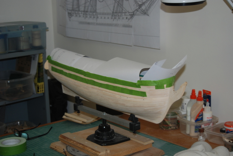
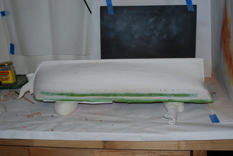
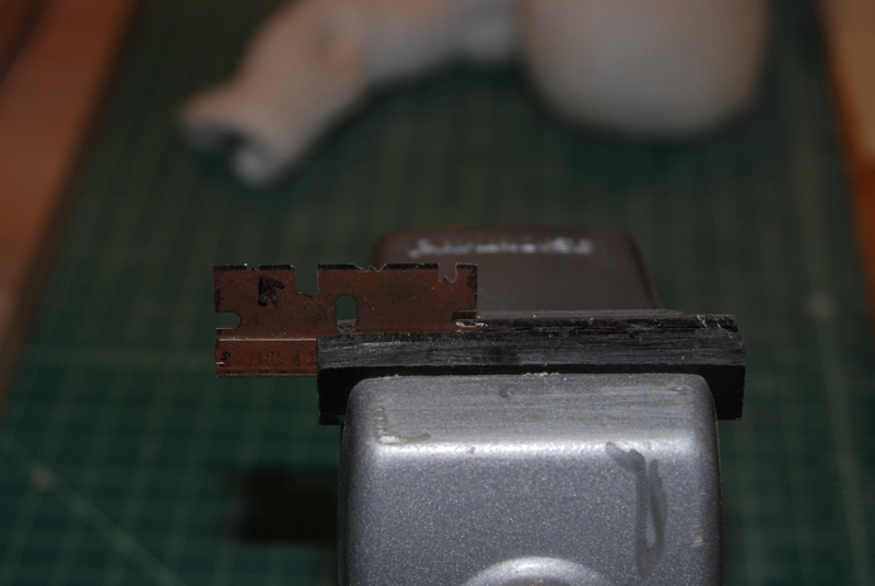
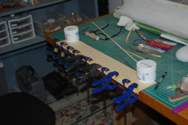
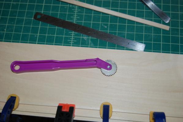
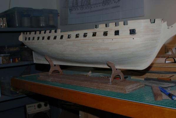
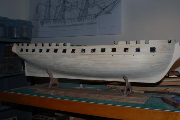
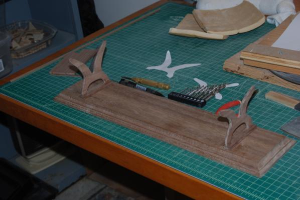
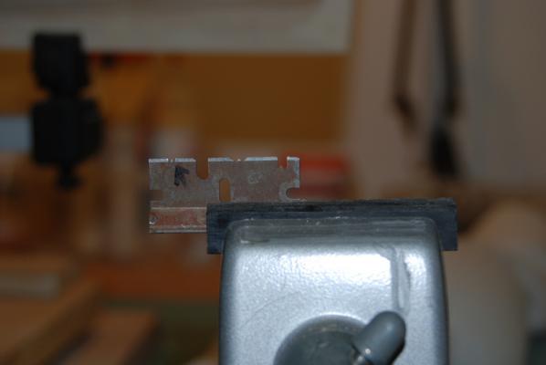
To finish up from yesterday's post, here is the completed cradle, just not with any finish yet. I'll wait to do that later. There are two brass rods in each support, going from the legs through the small support base pieces and into the large base board. I used CA to glue in the brass rods and wood glue under the feet and base boards. Everything is nice and tight so should be good without any additional support, I think. I can always add support bars between the supports, but I would rather not. I had bought that base board for a previous model but didn't use it. It made a good base for the cradle. I'll probably add some felt to the arms where they contact the hull, too. And here it is supporting the hull. I once had thoughts of carving the ends with the same billet head scroll as on the model, but the walnut seems too brittle to carve well. I may try adding some scrolls on the sides of the walnut, but we'll see. I gave the hull a final sanding in preparation for priming it. There is one last step to do before that though which is to add the boards that will cover the gap between the outer planking and inner planking across the open bulwarks section. These are sort of vestiges on the existing ship, as shown on the plans. They have a groove in the outer edges so to make that I ground a profile into an old razor blade with a Dremel cutting disk. The new profile is the deep one on the right. You can see some old ones that I used for other models with very unsatisfactory results. This one I made very deep so the tool won't wonder as I pull it across the edge, which was the problem with the old profiles. And here is the result. This strip is just laying in the opening. I need to prime and paint it before gluing it in, as it is right up against the green plank sheer on the inside. I am really happy with how the groove came out, especially since this is basswood which doesn't like to hold a nice edge. I used a very small file to increase the bevel on the inside edges of the groove and also to clean up the bottom of it. I rounded the outside edges with some sandpaper. I will start masking the hull tonight in preparation for spraying the primer. I am going to prime all the way down to the keel because I think it makes a good base for the adhesive copper tape. I have not had any problems with adhesion on previous models when I have primed the hull first. Plus, it will show areas that may still need some filler and/or sanding.

- 1,354 replies
-
- 9
-
-
- constitution
- model shipways
- (and 1 more)
-
Looks great, Rich, I like how the stand matches the colors of the hull.
- 1,756 replies
-
- 2
-
-
- constitution
- constructo
- (and 1 more)