

popeye2sea
-
Posts
1,933 -
Joined
-
Last visited
Content Type
Profiles
Forums
Gallery
Events
Posts posted by popeye2sea
-
-
-
-
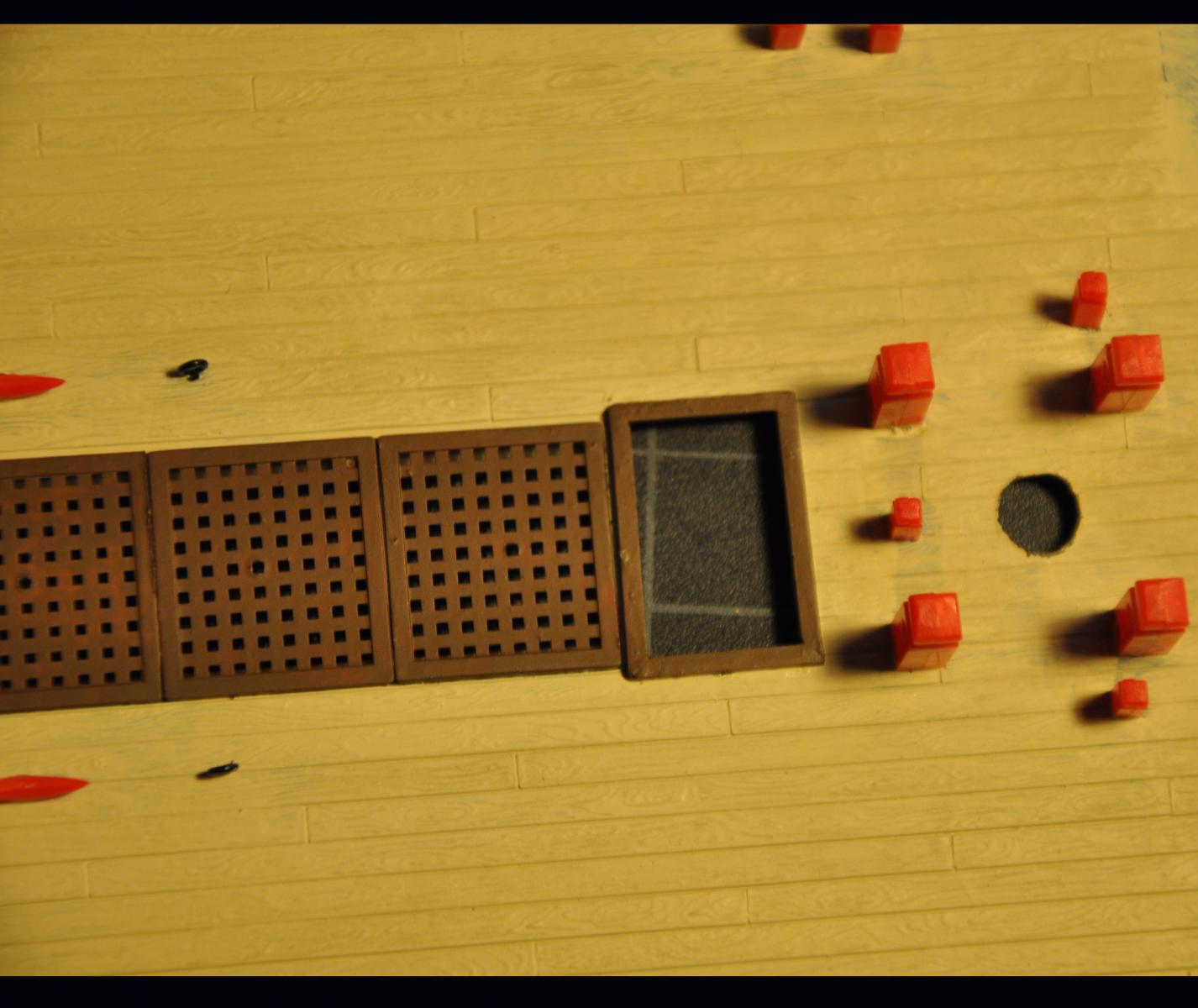
The decking under the main hatch looks great, however be advised, under the main hatch on the spar deck is a corresponding hatch on the gun deck and further below a hatch on the berth deck in order to get cargo into the main hold and orlop.
-
In addition to what has been said above, the sails were set by sheeting home the clews to the lower yard and then hoisting the yards up to their full height. The reverse was done to furl the sails.
-
Although I have fired a cannon several times I can not say with certainty how much of a blast would come out of the touch hole. The powder charges we use are much smaller than a full combat load. And to be honest, my position on the gun is either worm/loader or sponge/rammer, so I am usually at the muzzle of the gun when it goes off and not really paying any attention to the touch hole. My impression is that there is a plume of smoke but not much else. Also much of that plume is from the powder in the pan and touch hole.
-
Well, right now mine are either in an old cookie tin or on my work bench, so anything will help.
-
Barehook, I really like the look of that storage box.
-
The tackle is the system of ropes running through the blocks, i.e.: a block and tackle
Two blocks made up together in one strop is called a sister block. In fact, an example of two unequal sheaves in the same shell was a fiddle or violin block.
-
I bought a set of round nose ultra fine pliers from a company online called Micro-Tools (part # PLR-491-10).
I then ground one tip down to 1 mm, which is just over 1/32 inch. The grinding down was really just an increased taper and I tried to preserve the mating surface of the plier jaws.
The best way to form the loop is to grasp the wire between the jaws of the pliers in your right hand, the jaw that you are going to loop around (smaller jaw) away from you and the wire gripped so that it is at the very end. You do not want to able to feel the wire above the plier tip. You also want to make sure the the wire is perpendicular to the pliers or you will get an oval. Using the thumb of your left hand bend the wire around the small jaw of the pliers. Your thumb should be right up to the pliers and it is more of a pushing the wire around the jaw. You will need to turn the pliers in your right hand by turning your wrist without losing your grip on the wire. You may reach a point where you can not bend any further comfortably without losing your grip. You can adjust the the grip of the pliers so that the point at which they are gripping is further back along the loop by just turning the jaw slightly in the loop. This will allow you to finish closing the loop. Be careful not to move the wire up or down the jaws while doing this or you will get two different diameter bends in the loop.
Once the loop is made shift your grip on the wire by spinning the pliers in the loop until you are now gripping the straight section opposite the end of the loop. Bend the wire slightly in the opposite direction until you get the shaft of the eyebolt pointed in the right direction.
I use the same pliers for making rings for ring bolts and hooks for blocks. The hooks are made with five separate bends in the wire, but the principles are the same. It is important that you keep the wire perpendicular or your bends are going to be out of plane and at odd angles. Remember that you are not bending the wire with the pliers so much as you are bending the wire around the jaw. You will have a lot more control over how the bends look if you are doing all the bending with your hand and not the pliers.
Regards,
- WackoWolf and Geoff Matson
-
 2
2
-
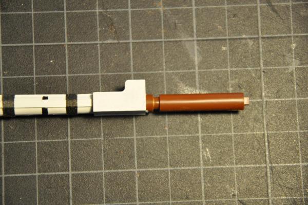
The worm that we use on our working 1812 era cannon is made from cast iron and the head looks like a spring. The arms really do not scratch the bore of the cannon at all. The pitch of the helix is smaller than you have depicted. The 'arms' make more that 2 complete revolutions. The sponge and rammer are on opposite ends of another pole.
In addition to unloading the gun the worm is used as part of the regular gun drill. Here is the drill we use. It was standard during the war of 1812
1. "Search your piece" The worm is inserted down the barrel and given several turns to snag any unburned wadding or cartridge left over from the last shot
2. "Sponge your piece" The wet sponge is run down the barrel to extinguish any burning embers
3. "Search your piece"
4. "Sponge your piece"
5. "Advance cartridge" The cartridge is brought to the loader
6. "Load cartridge" The cartridge is inserted into the barrel and rammed home
7. "Load with shot" The round shot (or other shot) is inserted into the barrel a wadding is inserted after and the shot rammed home
8. "Prick and prime" The gunner inserts the prick down the touch hole to pierce the cartridge bag and then fills the touch hole with powder. A lead apron is the placed over the touch hole to protect the powder.
The gunner then sights the gun and the crew uses handspikes to train and elevate the weapon.
9. "Make ready" The gunner blows in the linstock to make sure it is burning well. The apron is removed from the touch hole.
10. "Fire" The gunner touchs the linstock to the touch hole.
-
The rigging plan of my Soleil Royal (1669) has blocks on the shrouds used as fairleads for some of the upper rigging. I am not sure if this is a correct usage for this time period. My thought is that there should be wooden fairleads seized to the shrouds. Does anyone have some information regarding which is more correct for the late 17th century?
-
Thanks all,
Joe, a thousand more? Woo Hoo....think of all the builds I could finish by then

Dan, Thanks for the tip. A lot less work for me. Time to start ripping out all the ringbolts in the deck and filling holes

Regards,
-
halyard (n.)
 "rope for hoisting sails," 1610s, from Middle English halier "a halyard" (late 14c.), also "a carrier, porter" (late 13c. in surnames), from halen "to haul" (see hale (v.)). Spelling influenced by yard"long beam that supports a sail.
Rat Line Middle English radelyng
First Known Use: 15th centuryBunt (line)1. a : the middle part of a square sailb : the part of a furled sail gathered up in a bunch at the center of the yard2: the bagging part of a fishing netOrigin of BUNTperhaps from Low German, bundle, from Middle Low German; akin to Old English byndel bundleFirst Known Use: circa 1582Leech (line)1. : either vertical edge of a square sail2: the after edge of a fore-and-aft sailVariants of LEECHleech also leachOrigin of LEECHMiddle English leche; akin to Middle Low German līk boltropeFirst Known Use: 15th century -
Thank you all for the birthday wishes.
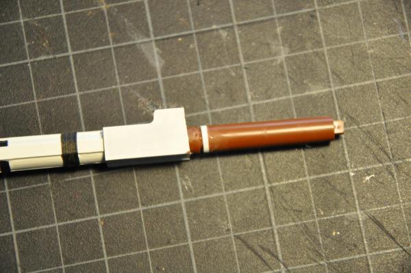
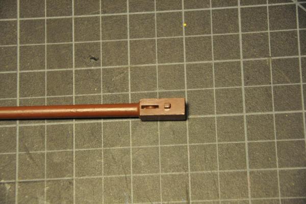
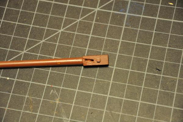
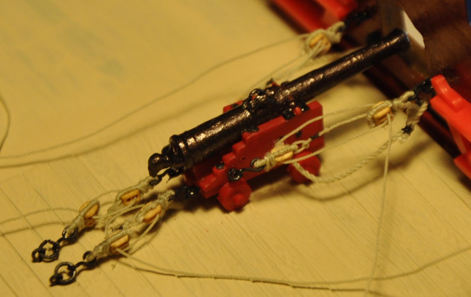
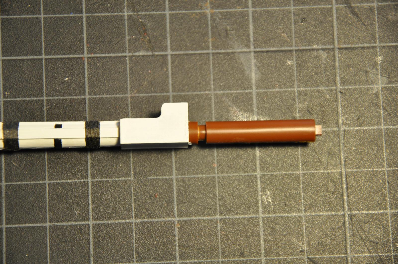
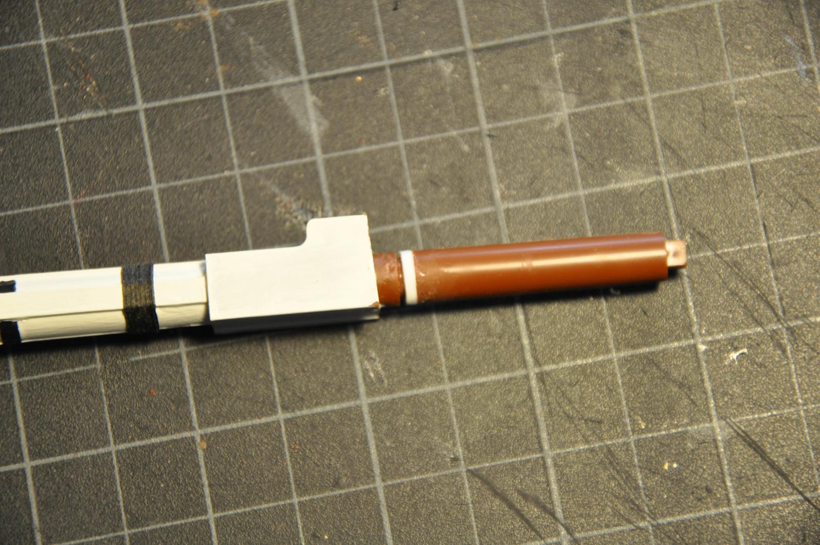
The build was a big hit at the Shipwright Guild meeting. I got some good tips on soldering techniques for the upcoming deadeyes and chainplates project. The cannon rigging continues....a long and tedious project. But, it is progress none the less. Of course it is taking longer because I keep refining my methods as I go along. The first cannon in place is a test piece. Here are some pics of it as it is today. I may still change some things. I think I will make the breeching thicker.
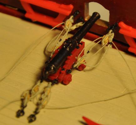
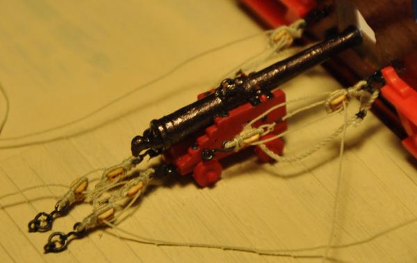
Thanks for looking in.
Regards,
-
A service (worming, parcelling, and serving) is applied to a line to resist damage to the line from rubbing and chafing. You would normally find parts of the standing rigging served over (for example: the upper portion of the shrouds and stays where they pass around the masthead, collars for stays and bob stays)
A seizing joins two ropes together or part of a rope to itself and can be found everywhere in the rigging.
-
-
Popeye, (I get the strange feeling that I am talking to myself here.
 Perhaps your me long lost pappy? )
The shrouds are not plastic. I will be setting them up in the correct manner in pairs with eyes around the masthead. That is why I added the bolsters, also.
-
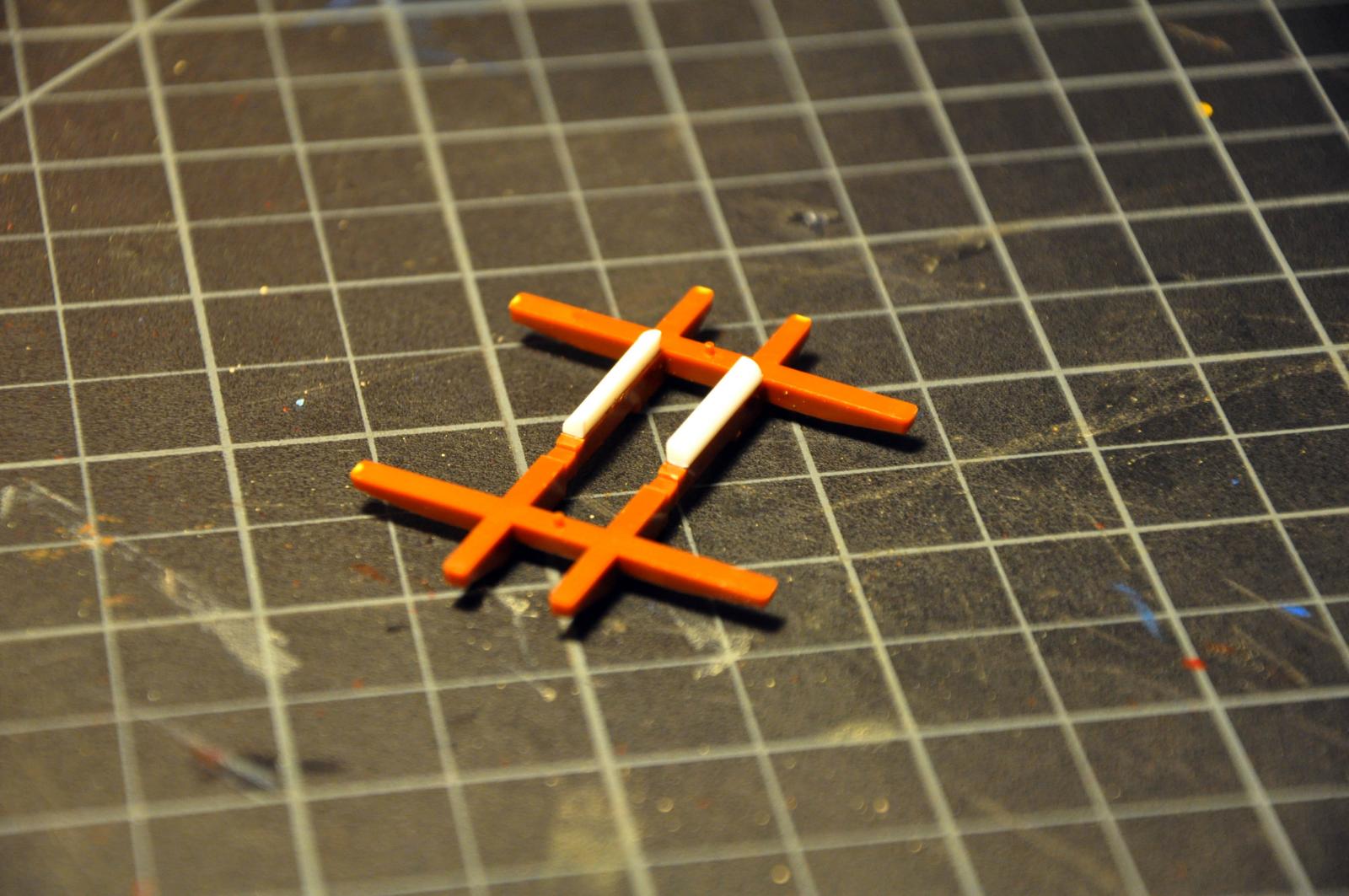
In between rigging 2mm blocks for all the cannon I decided to take breaks by doing some other small tasks.
For some strange reason the masts have a molded gap just above the hounds. Nothing goes in here and it looks out of place with the trestle trees in place so I filled in with strip styrene.
I changed the angle of the groove for the toprope to a better lead for the top block under the mast cap.
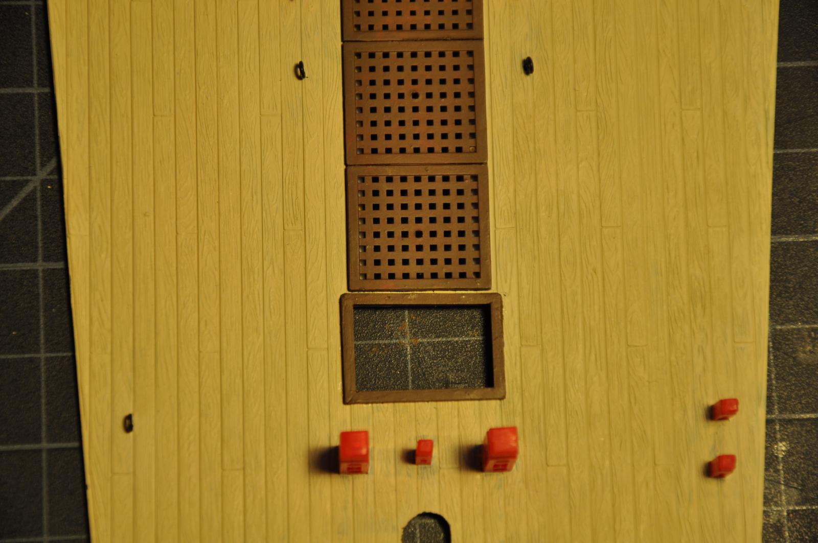
I added coamings to the companionways on the gun deck and quarter deck.


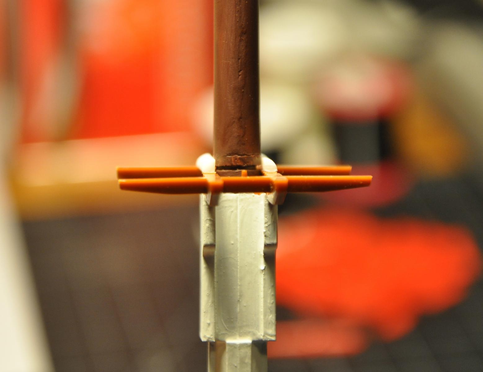
I added bolsters to the trestle trees.


Next up is adding eyebolts to the main and fore halliard knight heads. Of course I found out these were needed after the knights were installed in the decks and there is no room to get a drill bit in to make the holes. But, I'm sure I'll figure out a way.
Once I finish the cannons and the various parts on the decks I will run into the next big hurdle...deadeyes. The ones supplied with the kit are horrible. They are completely flat and the plastic strops are out of scale. I have been searching online for sources of deadeyes and most are disappointing and not the correct sizes. It seems that I am going to need 5 sizes of deadeyes from 5.5mm down to 2mm. I may try to make my own.
I'm bringing the build in on Tuesday for showing at the next Constitution Model Shipwright Guild meeting for critique and advise. The guild members, like the members here, always have great advise.
Thanks for watching.
- popeye the sailor, foxy and dafi
-
3
-
Steve,
Sorry for the long wait on this reply. Here is what I understand is a history of the ships configurations.
As built Constitution had open rails ( no enclosed gunwales) from abreast of the foremast to the taffrail with stanchions defining the gun ports on the quarterdeck aft of the main mast. The line of the cap rail did not follow the sheer line, it had a flatter appearance. Her bowsprit was steeved higher than it is currently. She had open head rails and ornately carved trailboards with a figurehead representing Hercules. She was pierced for and carried 30 guns on the gun deck and carried 14 carronades on the quarter deck (rated as a 44). The carronades on the fore deck were added later bringing her war of 1812 armament to 50 - 54 guns (including bow chasers). The transom was ornately decorated and had 5 windows
I believe that the first Corne painting that you posted depicts this configuration.
Sometime around 1802-1803 Captain Preble was fitting out for her Mediterranean cruise and it is at this time that the section of rail aft of the mainmast was closed in by a solid gunwale.
After a collision with President in the Mediterranean on Sep 12, 1804 Constitution lost her jib boom, flying jib boom and part of her bowsprit. Also lost were her figurehead and parts of her cutwater and head rails.. Repairs in Malta were functional only and her bow has never looked the same since. She received a billet head in place of her figurehead and the trailboards and head rails were not restored to her original appearance. The head rails were still open during the war with Britain. Subsequent overhauls and repairs would gradually alter her bow appearance to what it is today.
During 1812 Captain Hull opened three gunports in the upper transom (above the windows) in order to fire stern chasers at the British squadron.
The second Corne painting you posted shows this configuration.
During a refit in the 1830's the sheer line of the gun and spar decks was lowered aft of the main mast. 2 1/2 feet in height was added to the bulwarks from the main gangways aft to the transom. The fore mast was shifted 2 feet aft and its rake was increased 2 1/2 degrees. The main mast was shifted 2 feet forward. The mizzen was shifted 13 inches aft. The rudder port was lowered and the rudder head moved forward. A dog leg was added to the tiller to clear the deck beams of the lowered gun deck. The transom was moved slightly aft.
During her conversion to a school ship for the US Naval Aceademy in 1858 two of the windows of the stern were filled in
- CaptainSteve, GLakie and robnbill
-
3
-
-
On Naval vessels (modern) the bitter end of the anchor chain is shackled to a pad eye in the chain locker. I can't imagine that it would be left loose on any vessel. If it was ever to let loose and run free it would be too easy to lose the entire thing overboard. The last fathoms are painted red so that you know to set the chain brake soon or you are going to lose it.
-
The term applied to all the serving material that I have seen refer to " twine". So we are talking about small stuff. Seizing in my book would be made with somewhat thicker stuff
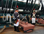
Incidentally. the Constitution pic shows what seem to be webbing straps - not something I have seen before - can anybody enlighten me on that subject ? Are they fastenings for a cover of some type?
Spyglass, the web straps are gripes for the boats. They hold the boats in.
-
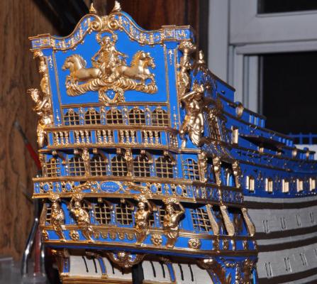
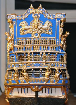
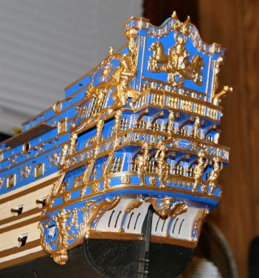
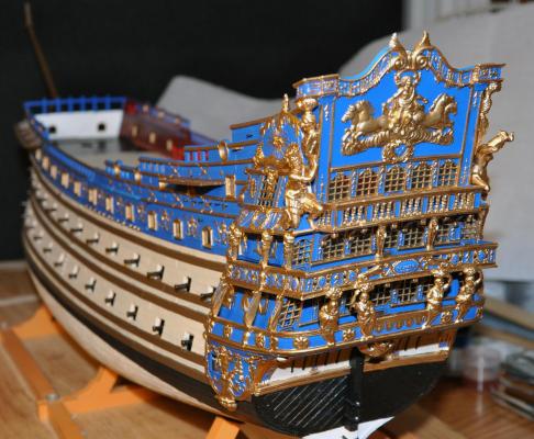
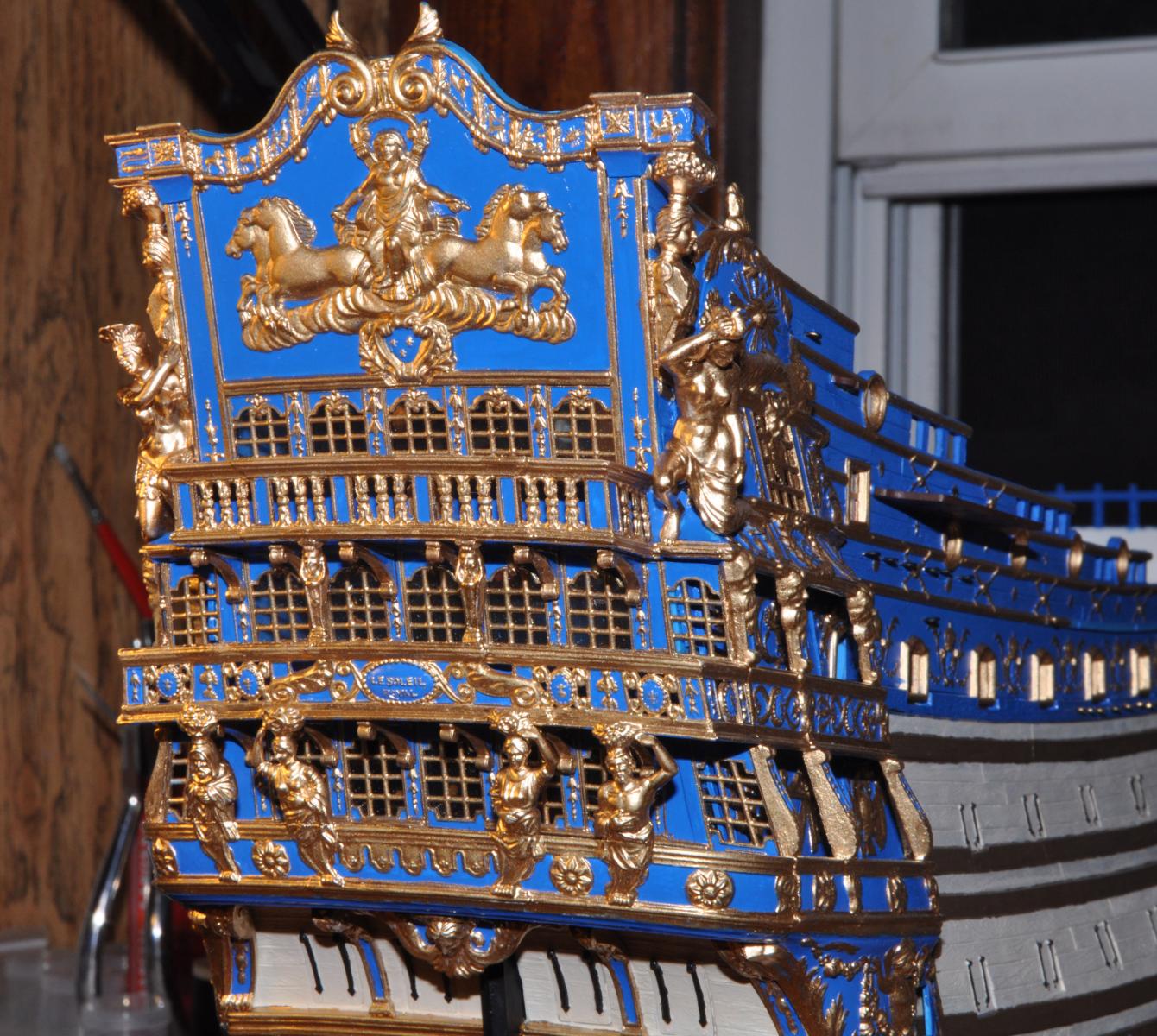
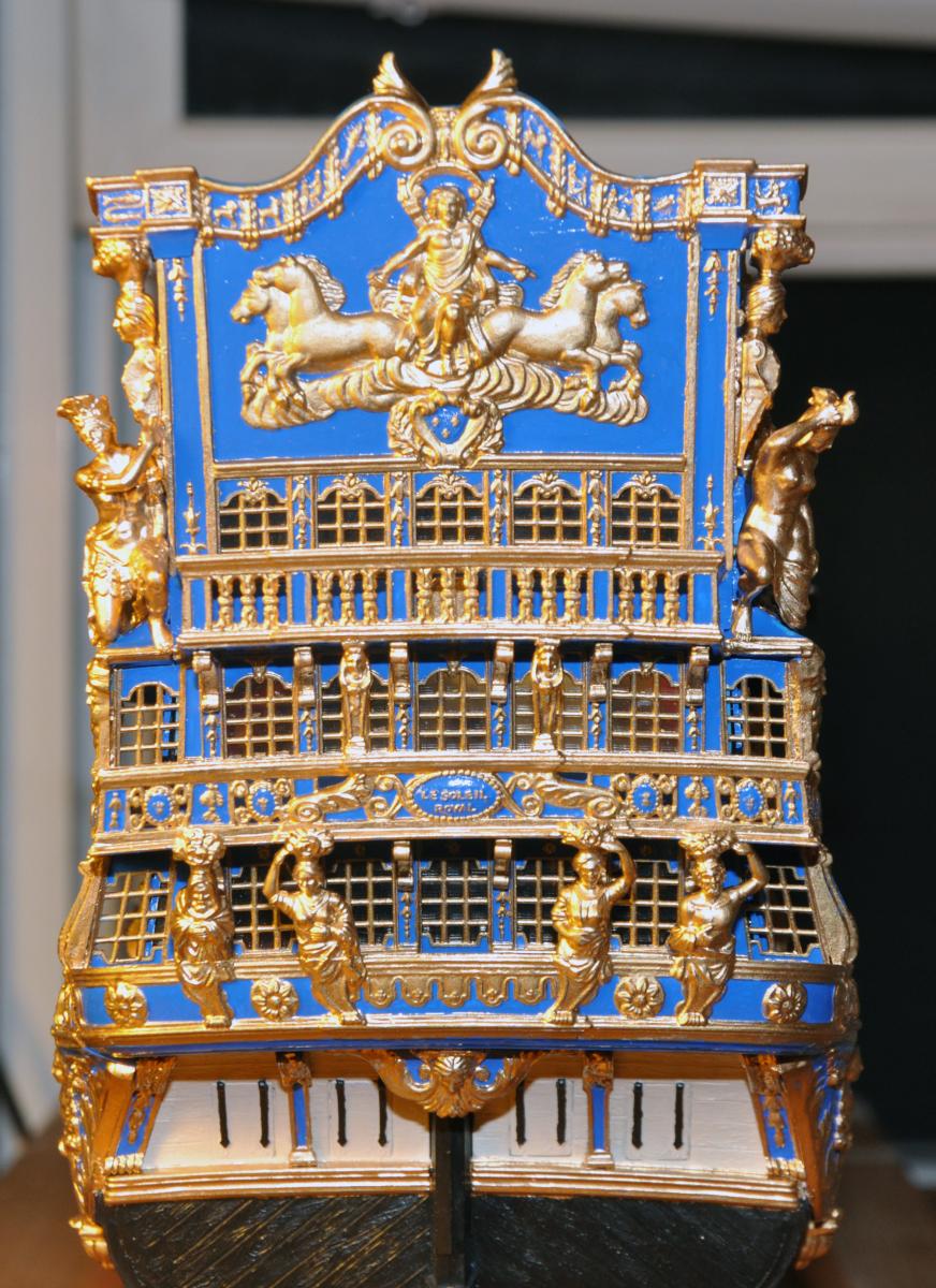
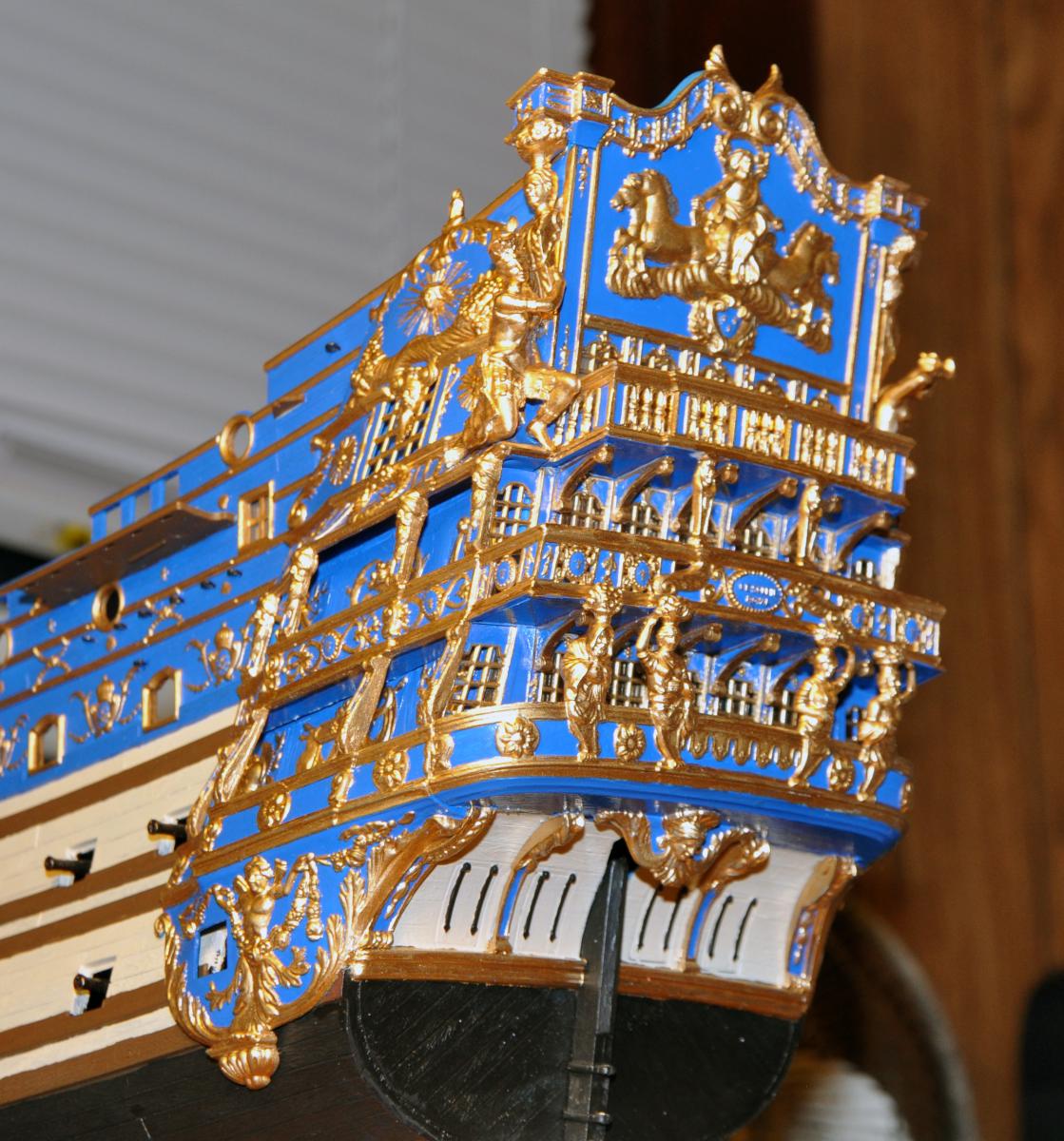
As I mentioned before, the stern of this kit is a series of difficult fitting jobs. The stern balconies were fitted in the order of lowest to highest. The balconies were aligned as well as possible using the side profiles as a guide so that they match up to the quarter galleries. Then the brackets were added to the undersides. Any filling that was necessary was then done followed by touch up painting. The carved pillars were added last followed by more touch up paint. I had to add some height to the carved pillars between the second and top balcony by using some strip styrene shaped to form a continuation of their pedestals. The large figures on the sides have no real attachment points so finding out where they actually come in contact with the various surfaces to prepare them for glue was interesting. Those contact points are rather small, hopefully they will adhere well enough. There remains to be added two reclining figures on the taffrail and the stern lanterns in order to complete the stern. I have to wait until the poop deck is in before I can finish.
Overall, I am quite pleased with the result.
Thanks for looking
Regards,
- CharlieZardoz, hexnut, ScottRC and 7 others
-
10
-
Although it is a hazard to the crew there is nothing I can do about that loose cannon. And I am not about to go jiggling the model upside down on the hope that it falls out through a ladder well.
 But now people can actually call me a loose cannon


Should all spars be aligned in the same direction?
in Masting, rigging and sails
Posted
Not sure what the proper answer here is but my gut feel is that no one would really justifiy spending the time and energy bracing round yards that did not have their sails set.