Supplies of the Ship Modeler's Handbook are running out. Get your copy NOW before they are gone! Click on photo to order.
×
.JPG.ca33079f5815b861e67b9c2cccd37982.JPG)

Blue Ensign
-
Posts
4,551 -
Joined
-
Last visited
Content Type
Profiles
Forums
Gallery
Events
Everything posted by Blue Ensign
-
 I think you will get an acceptable finish Glenn, well done. For those minor gaps in the strakes, run a bead of pva along the gap, sprinkle Boxwood dust over it, smear with your finger, and sand. Repeat as required. B.E.
- 587 replies
-
- 4
-

-

-
- Indefatigable
- Vanguard Models
- (and 1 more)
-
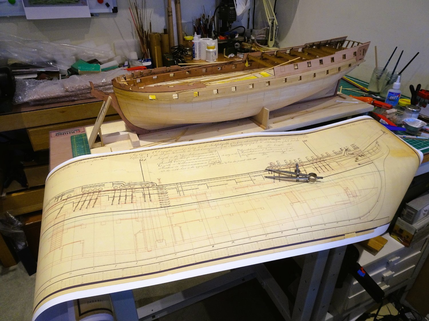
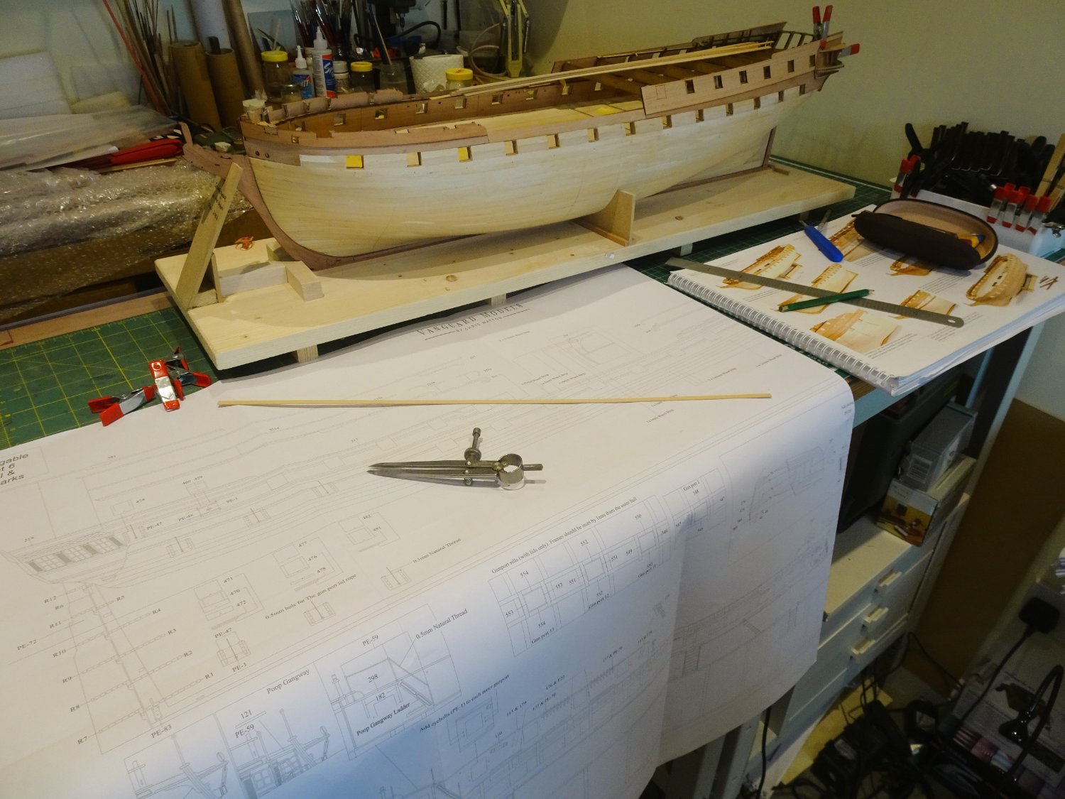
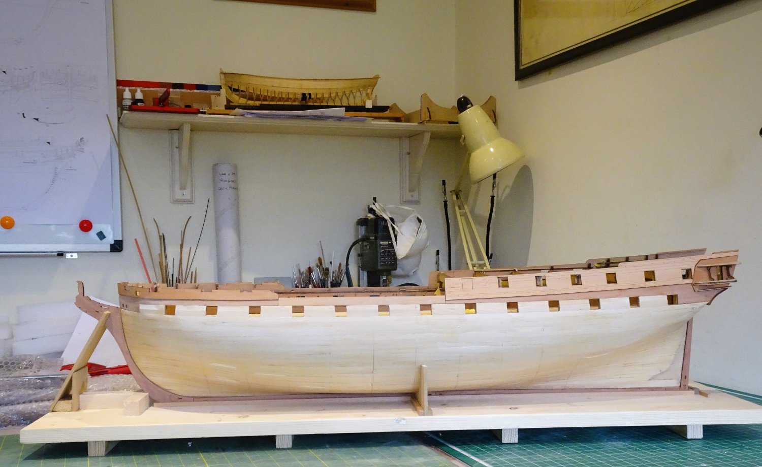
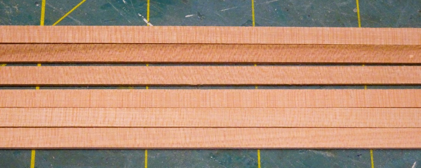
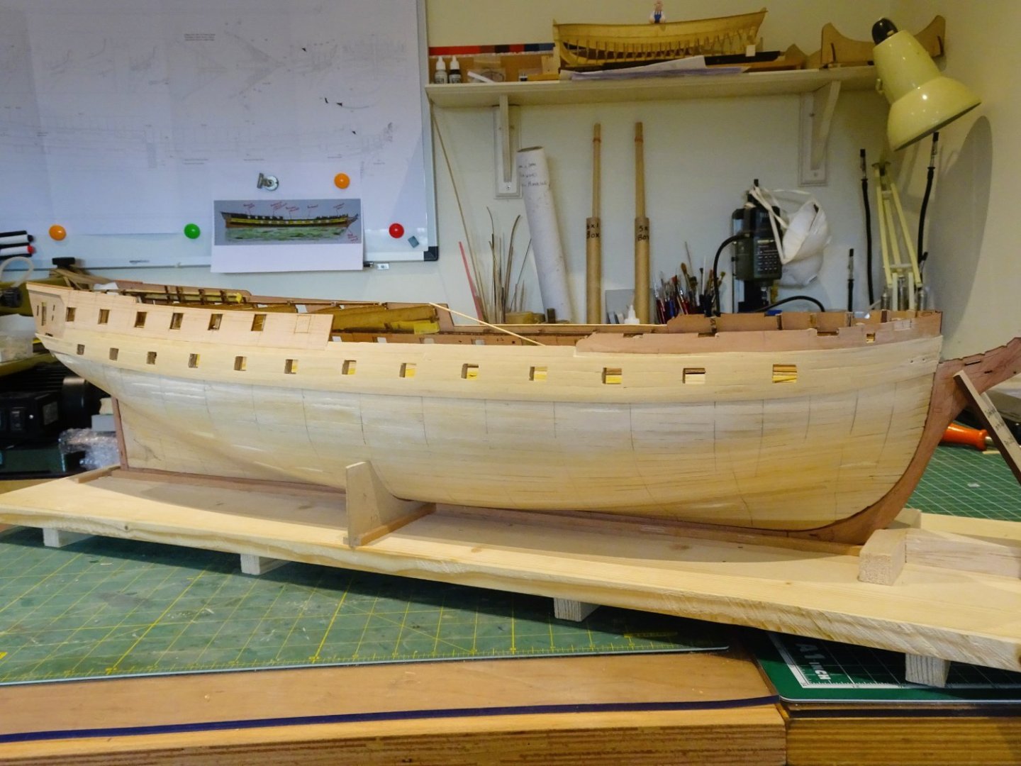
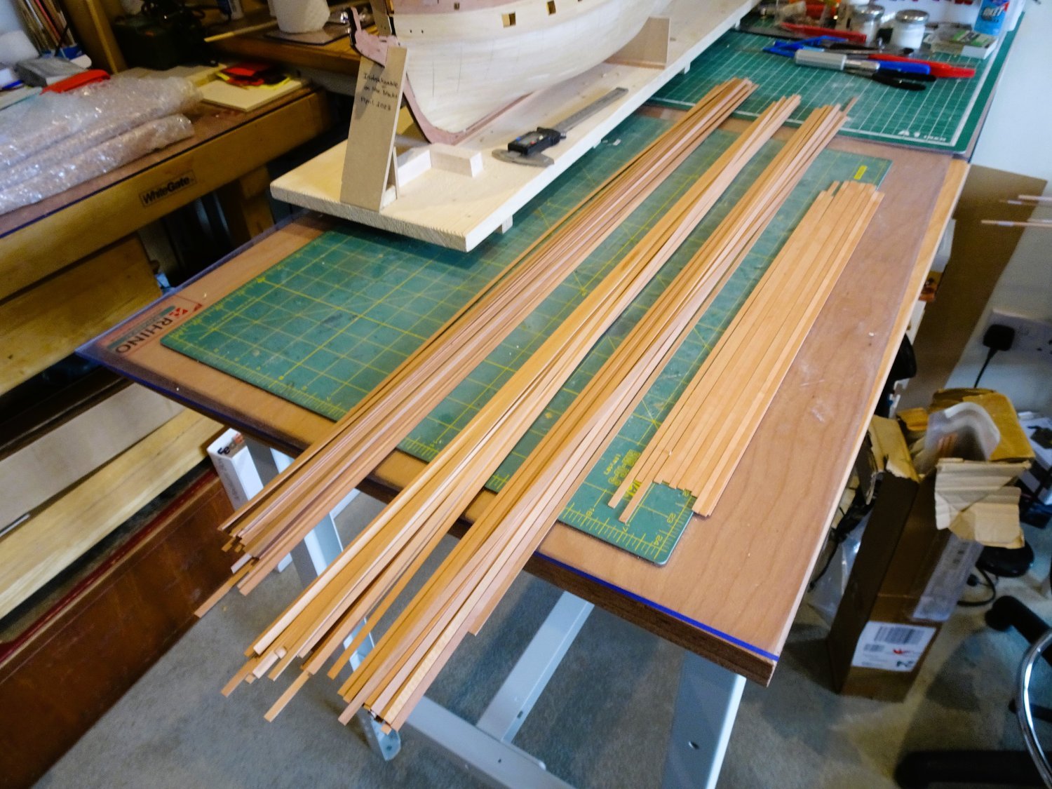
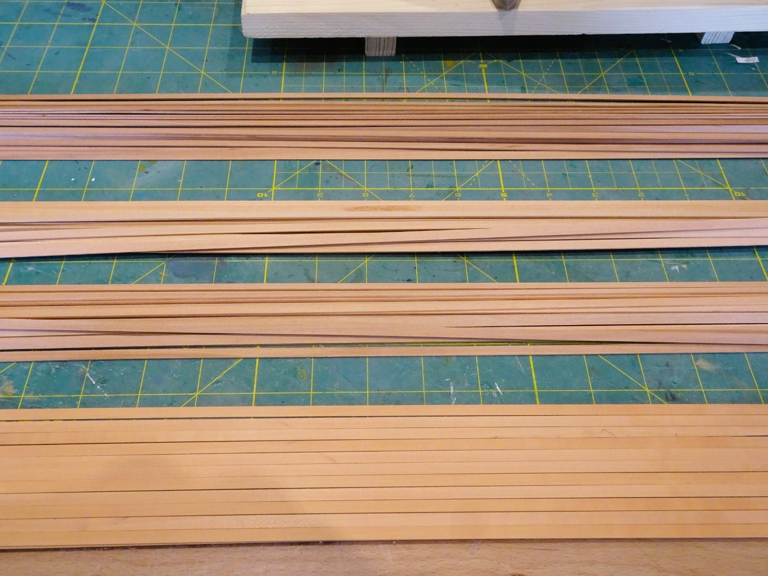
Post Thirty A conundrum I have spent the afternoon sorting and checking my planking strip. (102) 900mm lengths of 5x1mm Pear strip is supplied for the hull planking. There is quite a colour variation which may be split into three shades, Dark, light, and medium. 0956 In my kit (37) are Dark, (24) are light, and (25) are Medium. 0955 The shorter lowest selection in the above photos is Light pear from hobbymill.eu and from previous experience the colour is consistent. 0957 There is also a fourth category (16) strips, with vertical graining, that I prefer not to use. Mixed colour shades applied either randomly, or by design, in the planking strakes is something that doesn’t appeal to my eye, but if the intention is to copper and paint the hull then this is of little relevance. For me it means that there is insufficient strip to complete the hull without distinct colour variation along the strakes. As I hope to leave the hull with a natural wood finish this is a little disappointing, but I infer no criticism of the kit. My thoughts are turning to buying a new supply of timber from hobbymill.eu, an indulgence maybe, but this is a project that has already incurred a not inconsiderable cost, and I want to make it as good as I can. I was quite happy to have a Pear lower hull, but the situation now provides the option of replacing pear with Boxwood, and also including wider strips for spiling. There is only a small difference in cost between Pear and Box. One of the general downsides of kit timber is the lack of wider strips for hull planking, which is really is a bonus in planking. Fortunately, wider stuff is now more readily available from specialist sources. Using Pear I would have a contrast below the wale and a match to the stem, sternpost, and keel. With Box these elements would provide a contrast to the main hull planking, and Box is my favourite modelling timber. 08070 Nevertheless, I have decided to opt for Pear as demonstrated on my Sphinx build, above. I quite fancy a slightly darker lower hull, and if my planking standard falls below what I hope, then the hull will be coppered anyway. I now have a few weeks wait for the new timber to arrive, but meanwhile I can fettle those gunports, and mark up the hull for the planking runs. B.E. 11/05/2023


-Copy.thumb.JPG.3d289d353b4b8566bea20dd854f6c734.JPG)
- 648 replies
-
- 21
-
-
- Indefatigable
- Vanguard Models
- (and 1 more)
-
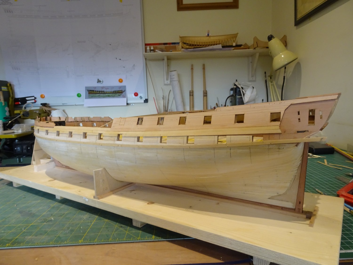
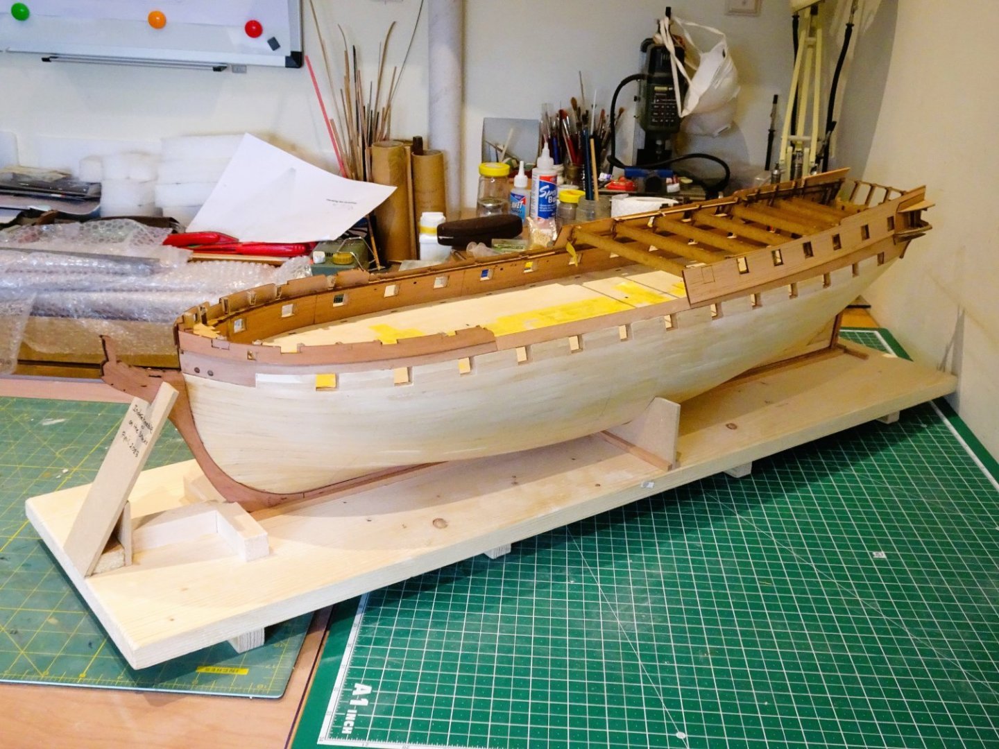
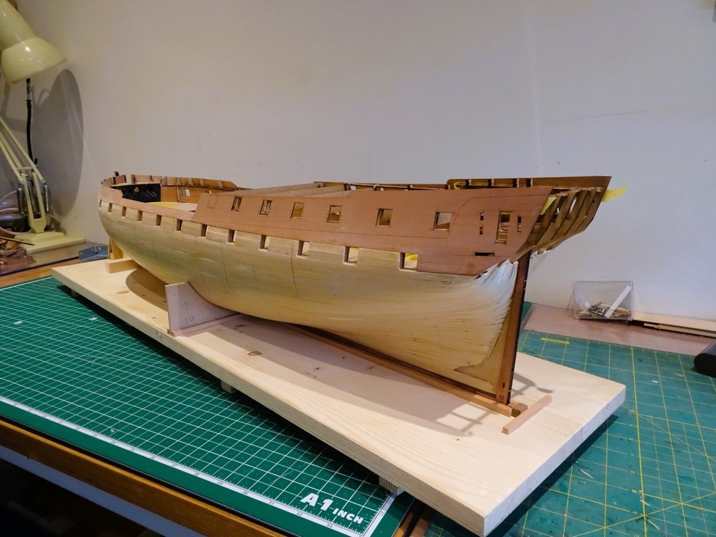
Thanks for the 'likes' and continuing interest Guys. Post Twenty-nine Planking continues. After a couple of fine weather days and a Bank Holiday weekend enjoying the Coronation, I returned to finishing the Topside planking on the Port side. 0942 0944 0945 0947 0948 0951 0949 This marks the limit of the Boxwood hull planking, from hereon I will be using Pear. Before I can get to the planking there is the wonderful world of tick strips and bandings to set up, and butt shift patterns to consider. B.E. 10/05/2023


- 648 replies
-
- 31
-
-
- Indefatigable
- Vanguard Models
- (and 1 more)
-
I think she will look good Kevin, nice working of the wale around the lower counter. 👍 B.E.
- 443 replies
-
- 9
-
-
- Indefatigable
- Vanguard Models
- (and 1 more)
-
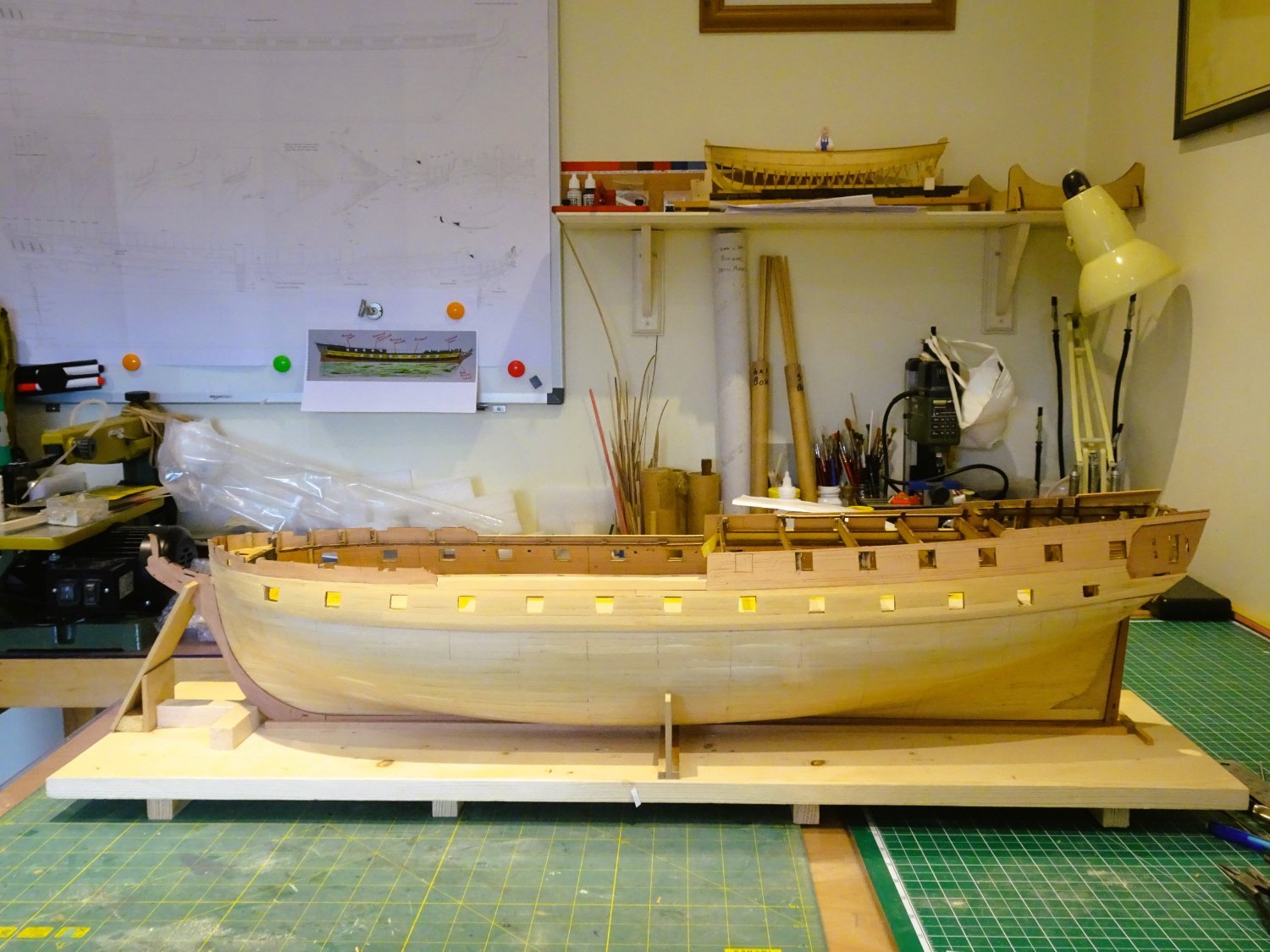
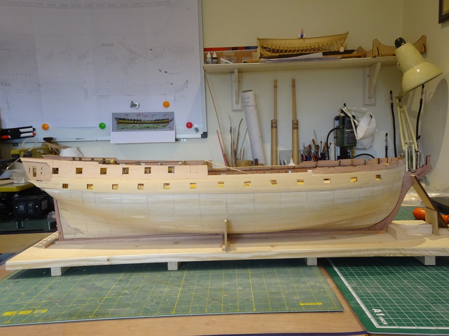
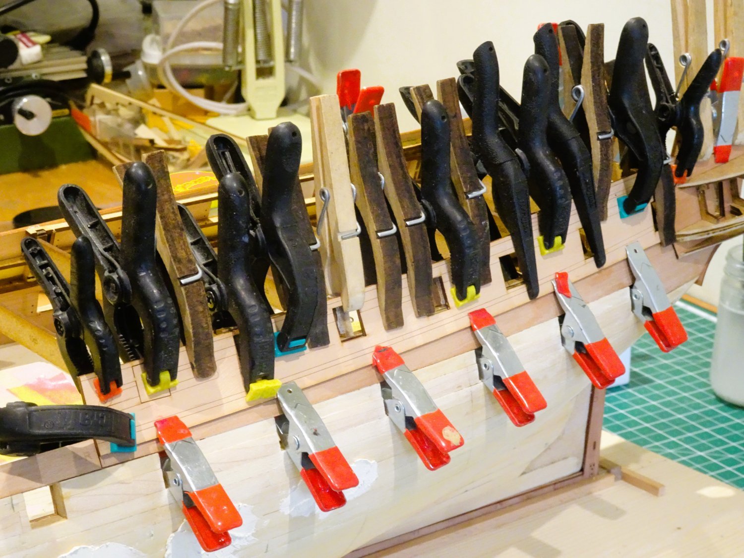
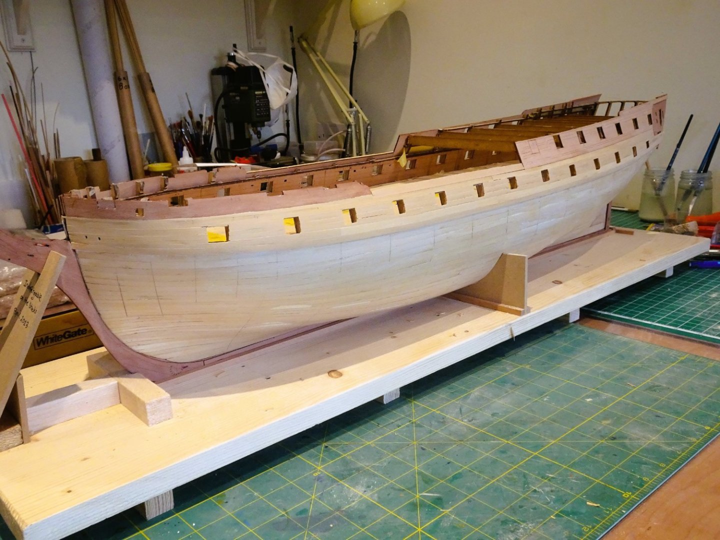
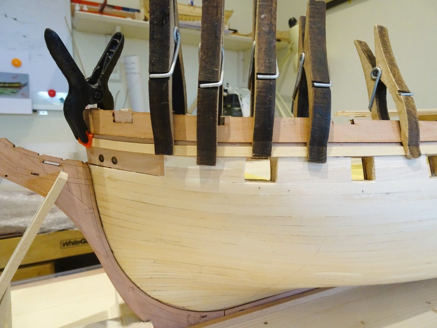
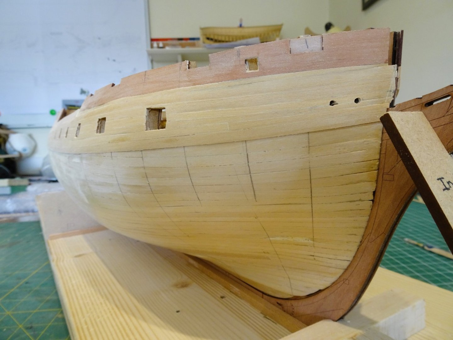
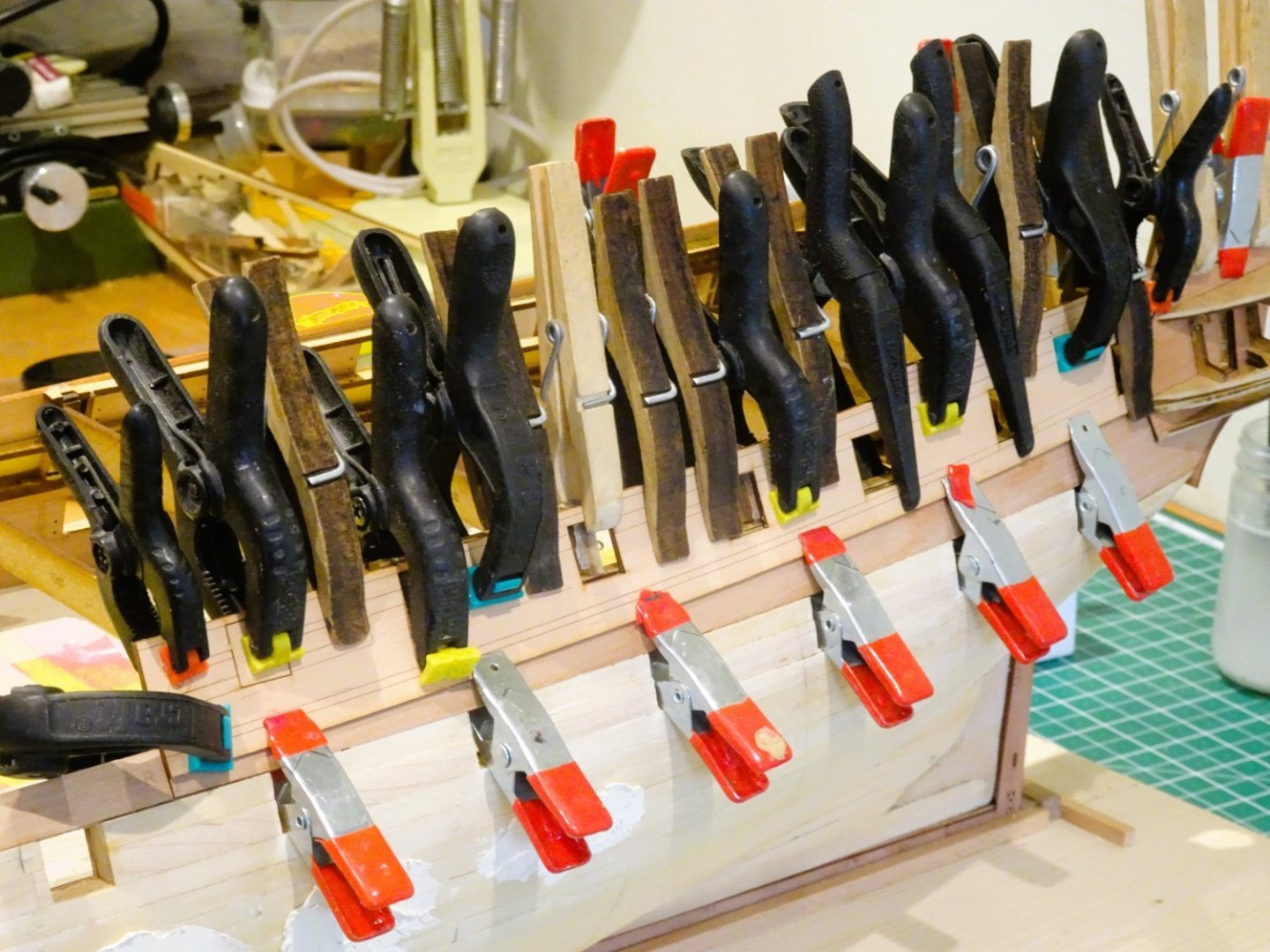
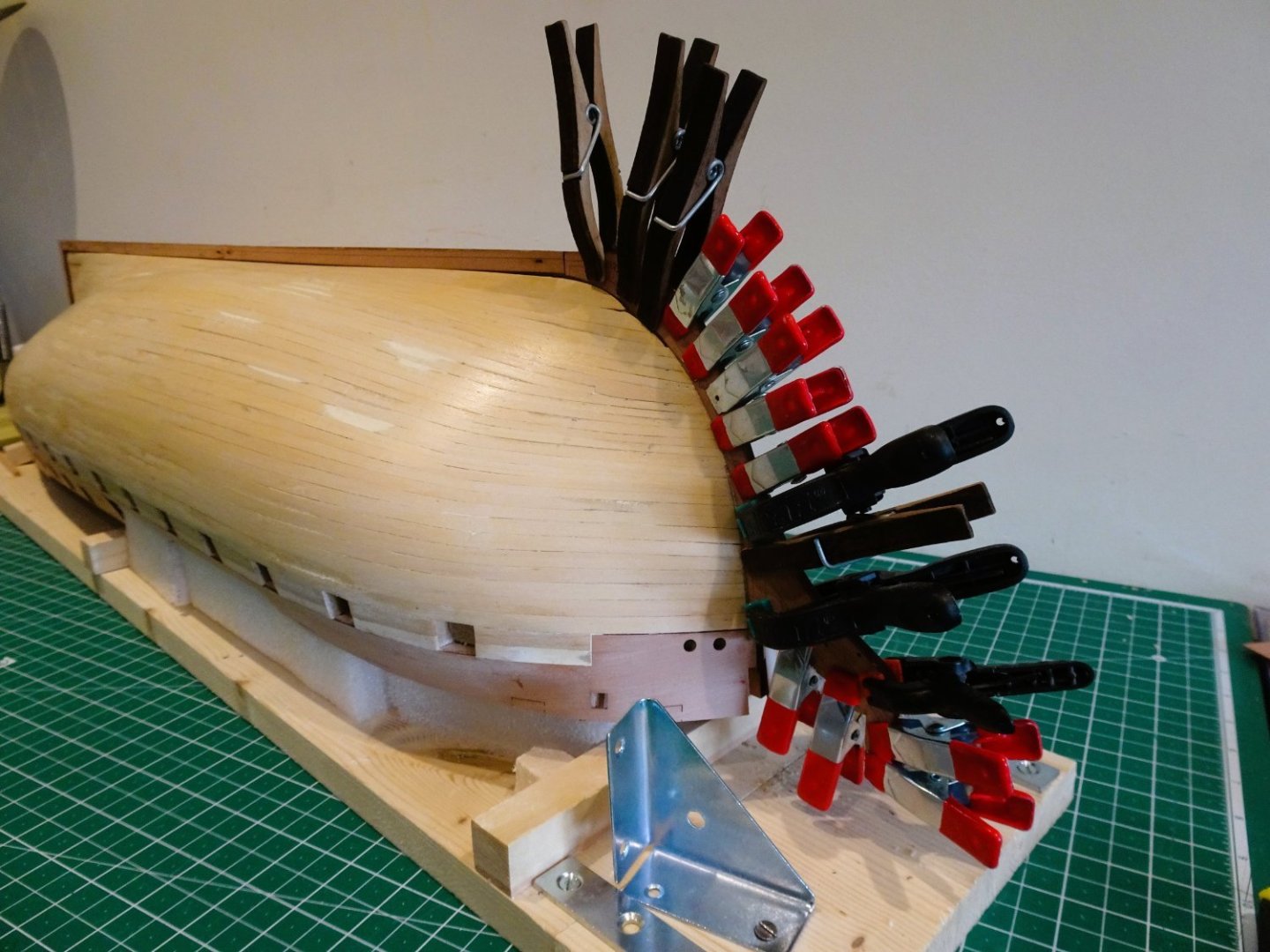
Post Twenty-eight Second planking begins I start by taking the trouble to sort and match the Box planking strips I obtained from Hobbymill eu. They are well colour matched and consistent in dimensions. So, time to apply the first Box plank. 0925 The blurb indicates fitting the first plank directly underneath the outer pear bulwarks; seems simple enough, but when it comes to the bow pattern there is an inconvenient gap between plank and pear bulwark of around 2 -3mm. 0938 The second plank fitted without issue; I used ca to start at the bow but followed by using pva for the remainder. It is possible to clamp these two strakes. Both strakes were fitted without tapering. The manual suggests the strake that represents the top level of the Wale (in fact the Black Strake) is next fitted. 0924 The line is taken from Plan six and marked on the hull below the gunport centres. (above the ports in the case of the aftermost two) It is then a matter of running the plank along the hull. I pinned the plank to the hull, and applied heat to form the shape. Pins are not an issue with this plank as it will be covered by a further wale plank. I opted to plank the topsides down to it, and then glue it into place. My preference is to part clear the ports as I go along. Fixing the planks between wale and topsides is not quite as straight forward as it may seem, if the intention is not to cover it all in paint. In that case the paint will hide a multitude of sins. On many kits the wale line is marked after the second planking has been applied, and I suppose this could still be done. It is just a matter of marking the dots on the second planking rather than the first. This would I think simplify the topsides planking. 0937 The wale sweeps up at the stern and bow, more so at the stern, and has a slight concave curve around midships. 0934 This means the planking between the gunports and down to the wale will have to be made to fit, requiring tapering at both bow and stern. Starting with the stern I tick stripped each gunport to determine the taper. The hull mid-section is broadly full width with tapering stating around the second gunport from the bow, and fourth from the stern. 0928 0940 Not an entirely authentic method of planking the Topsides, but the taper at the bow will be masked by the hawse bolsters and at the stern by the Qtr gallery lower finishings, so little to draw the eye. I am using ca gel exclusively now, but take the precaution of having a container of acetone and cotton buds handy to remove any ca spillage. 0933 0926 0930 0941 After five days the topsides planking is completed on the Starboard side. A preliminary sanding has been applied, but the gunports remain unfinished at this point. Onwards… B.E. 05/05/2023.


- 648 replies
-
- 34
-
-

-
- Indefatigable
- Vanguard Models
- (and 1 more)
-
Commiserations, from one Spaniel man to another, but your Indy can still look wonderful with a sharp paint job. Onwards, Kevin. B.E.
- 443 replies
-
- 10
-
-
- Indefatigable
- Vanguard Models
- (and 1 more)
-
Well done Glenn, that will clean up very nicely. B.E.
- 587 replies
-
- 4
-
-
-
- Indefatigable
- Vanguard Models
- (and 1 more)
-
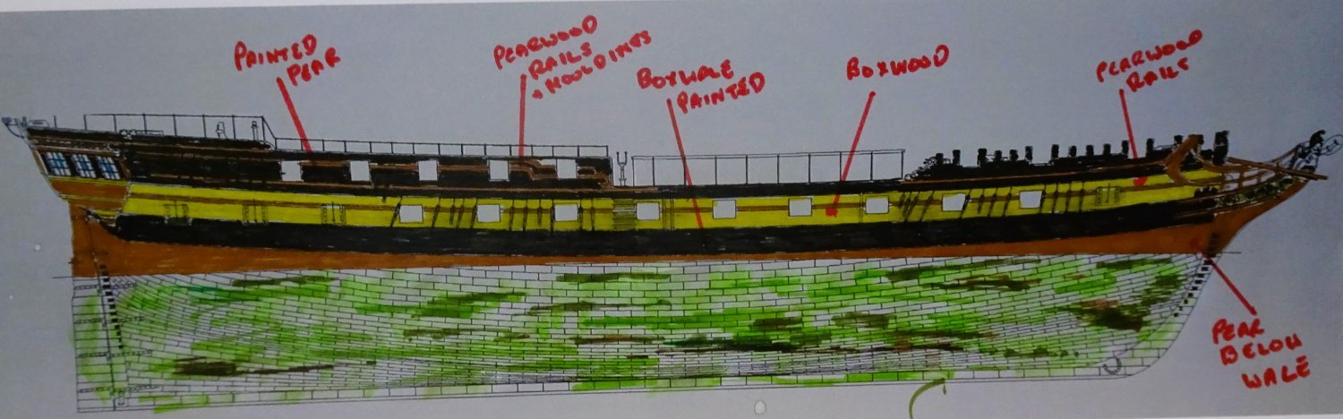
Thank you Jim and Kevin, much appreciated.👍 Post Twenty-seven The plan. Before I proceed to the planking, I need to consider the colour scheme of Indefatigable, and how I will represent it using a minimum of paint. I am not concerned here with the standard colour schemes of the late Napoleonic era British warship as represented by the Indefatigable kit, altho’ I’m not a fan of the bright yellow paint job on the prototype model, but that’s down to personal preference. I will be using a combination of Pear and Boxwood for the hull planking, and I hope to display the natural beauty of these expensive woods rather than cover them with paint. My idea is to use Boxwood down to the wale which will represent the ‘yellow.’ The application of w-o-p will darken and enrich the Box colour in this area. On the kit the ‘ochre’ stripe authentically follows the deck lines which means it overlaps the wale, particularly at the stern where the ports cut into the wale. Below the wale I will use Pear for the lower hull, the kit provided pear is too good to waste, but it will be supplemented with wider strips for Garboard use, and other spiling requirements. The topside Pearwood panels will be painted black, but I may leave the rails and mouldings natural. 0922 This rough schematic shows the approach I will be taking. The main departure from the kit suggested scheme is that the wales are painted without regard to the deck levels, and the woodwork below the wales will be left natural. The wale itself will be painted black or a variant thereof. I have yet to decide whether to apply either Top and butt or Anchor stock planking to the wale. I did on Pegasus, and Chris kindly provided it on Sphinx. I am undecided regarding coppering, a lot of extra work, but I quite like the effect. I have thoughts of partly coppering her, to demonstrate the use. My preference is for that ‘old penny’ look and like the idea of aging the copper using the method pioneered by Alistair (Aliluke) on his HMS Fly build. Of course, a build is dynamic and subject to change as things progress, but it’s good to have a plan in mind at the start. B.E. 01/05/2023

- 648 replies
-
- 21
-
-
- Indefatigable
- Vanguard Models
- (and 1 more)
-
Jean Boudroit explains that the Bowsprit cap is offset to Starboard since if it were central to the axis of the Bowsprit it might obstruct the rigging which follows the line of the Bowsprit. The riggers of British ships were obviously not of the same opinion. The Helmsman did not apparently need a clear view for steering, he responded simply to orders. I suppose one advantage of having the wheel in that position is that it is more protected, and the tiller and lines are shorter. B.E.
-
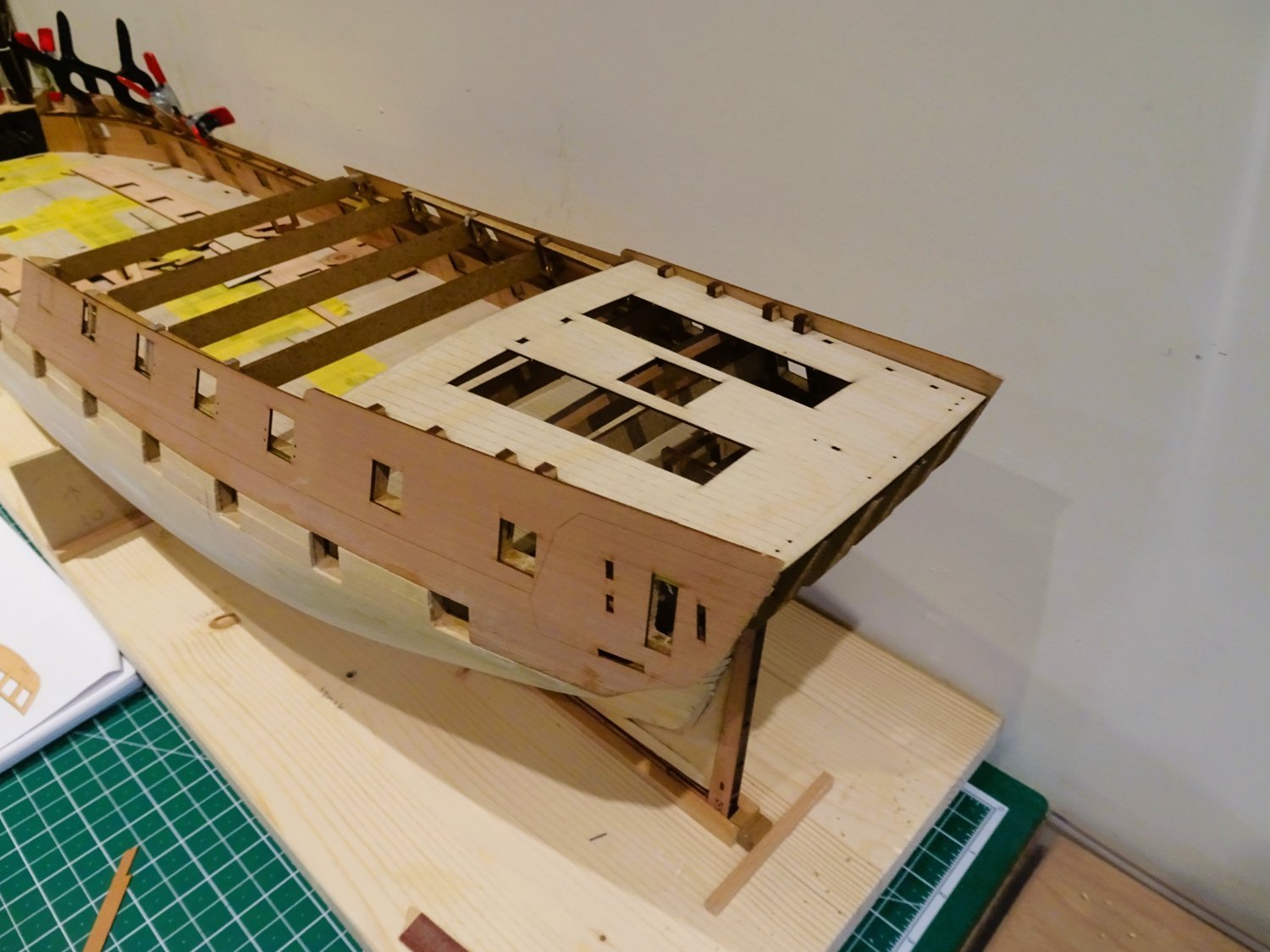
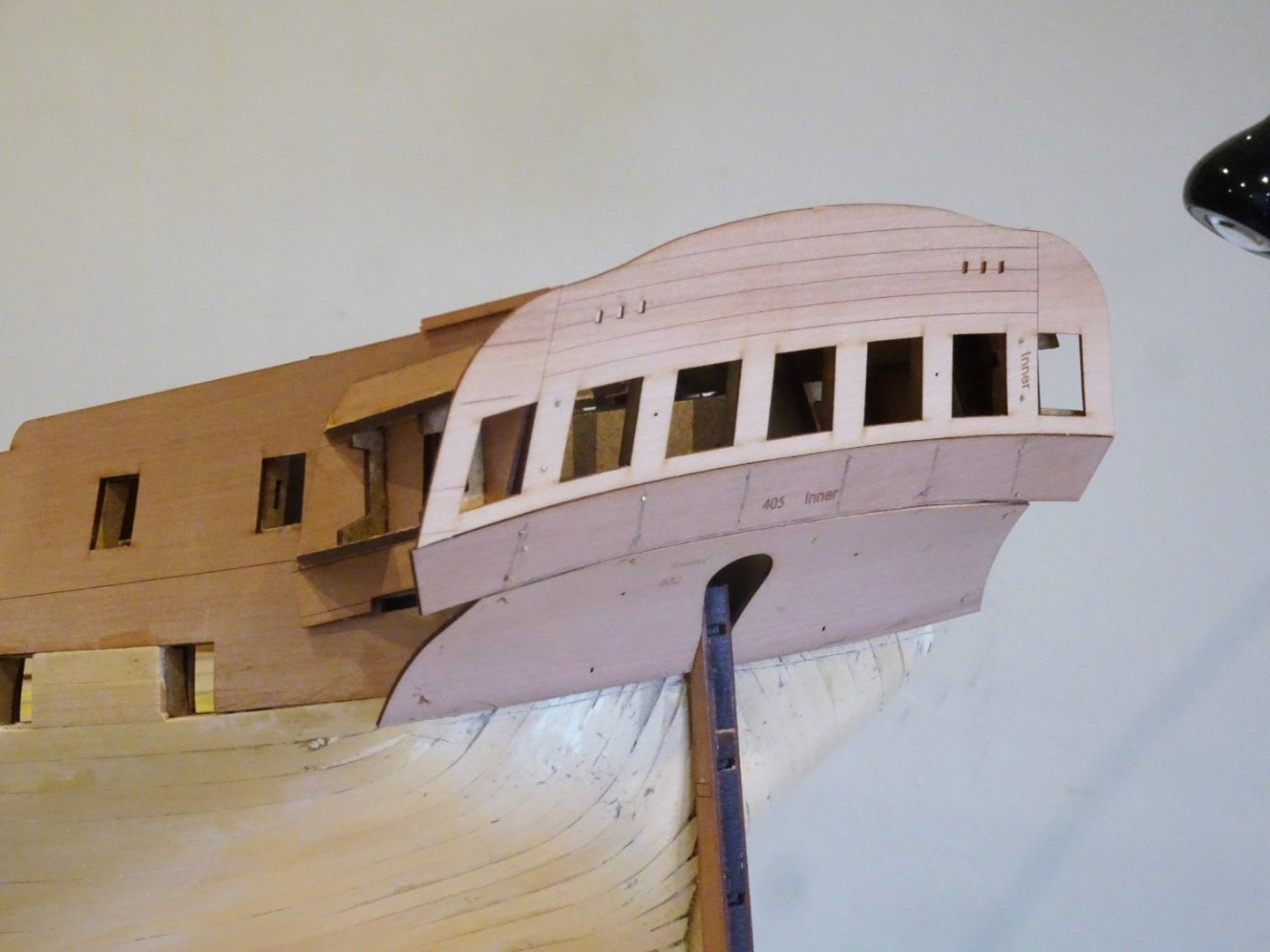
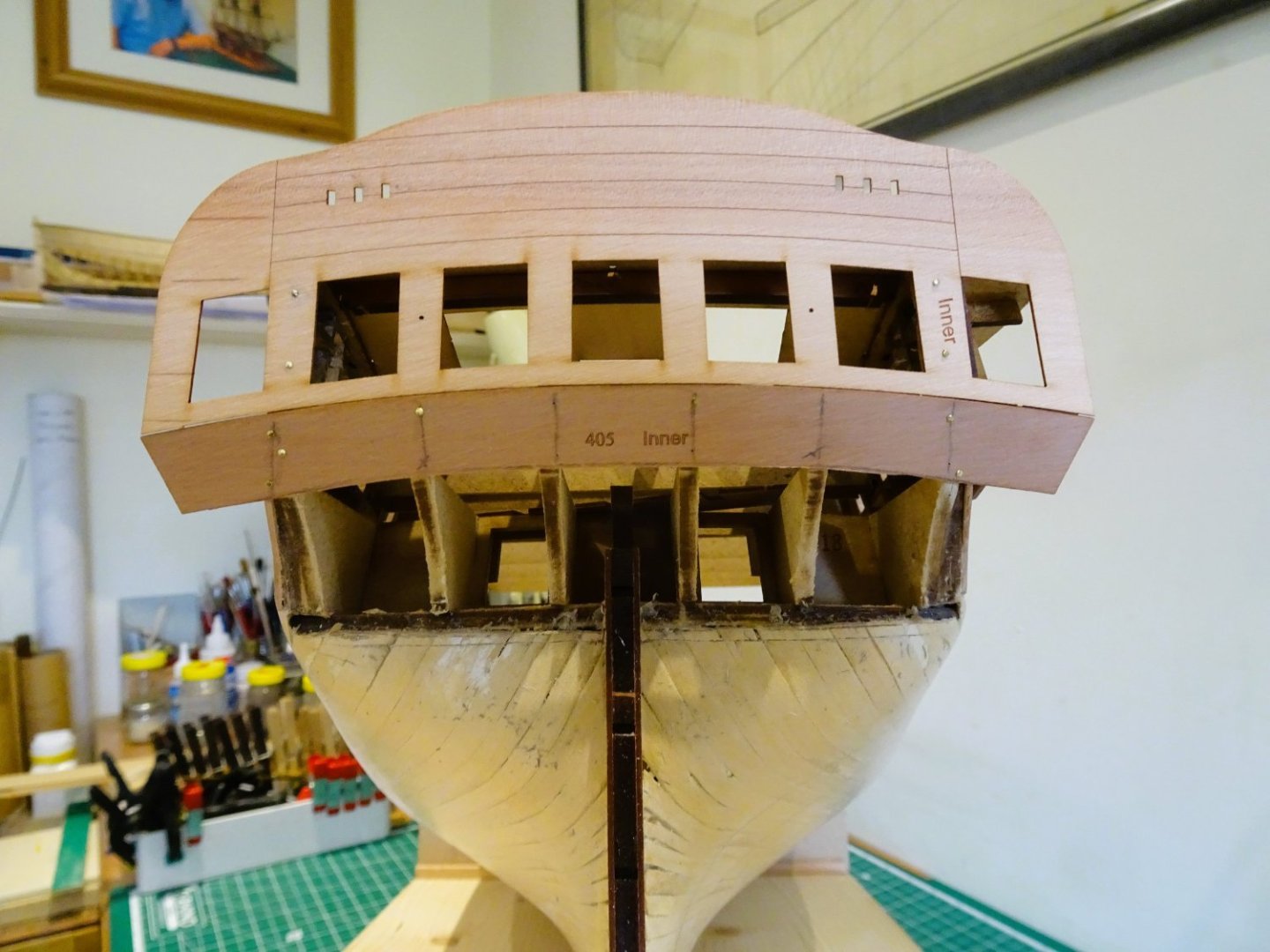
Post Twenty-six Fitting the outer Hull Patterns completes the cladding of the qtr deck bulwarks. 0906 Note. Section #208 indicates parts #246/250 but should be read as #252/253. These are the outer patterns. Parts #246/250 are the first layer outer patterns fitted earlier in section 155. 0917 0915 0916 I’m still fiddling around with the hull spotting noticed areas in the planking that would still benefit from a little extra fettlin’. A few low areas were re-filled and sanded smooth. The better I get the hull at this stage, the better the second planking should be. 0920 The final job in this section is to add the lower counter outer pattern. 0919 This stage represents only two months’ work but feels much longer. I now need to work out a strategy for the second planking. B.E. 30/04/2023

- 648 replies
-
- 30
-
-
- Indefatigable
- Vanguard Models
- (and 1 more)
-
The bench also doubled up as an arms store, but would be considered, an unnecessary luxury in British eyes for whom 'sitting down on the job' would be anathema. The entire Berthing to the main ladderway is very French and would probably have been removed on refit. What to do with it really depends on how easily it can be removed and what lies beneath. If there is a ladderway down to the upper deck then the usual British arrangement could be put into place. You are still left with making new ladders to the Poop deck, the usual arrangement is one either side, which would then require modifying the solid Poop deck rails. B.E.
-
You do have another bite at the cherry Kevin, copper the bottom, paint the wale black, there will still be a nice Boxwood contrast between that and the Topsides. B.E.
- 443 replies
-
- 6
-
-
- Indefatigable
- Vanguard Models
- (and 1 more)
-
If it’s individual planks that have been sanded through, could the section not be removed, and replaced? I have done this using a scalpel blade and fine chisels. Any residual ca can be removed using acetone. Just a thought. B.E.
- 443 replies
-
- 9
-
-
- Indefatigable
- Vanguard Models
- (and 1 more)
-
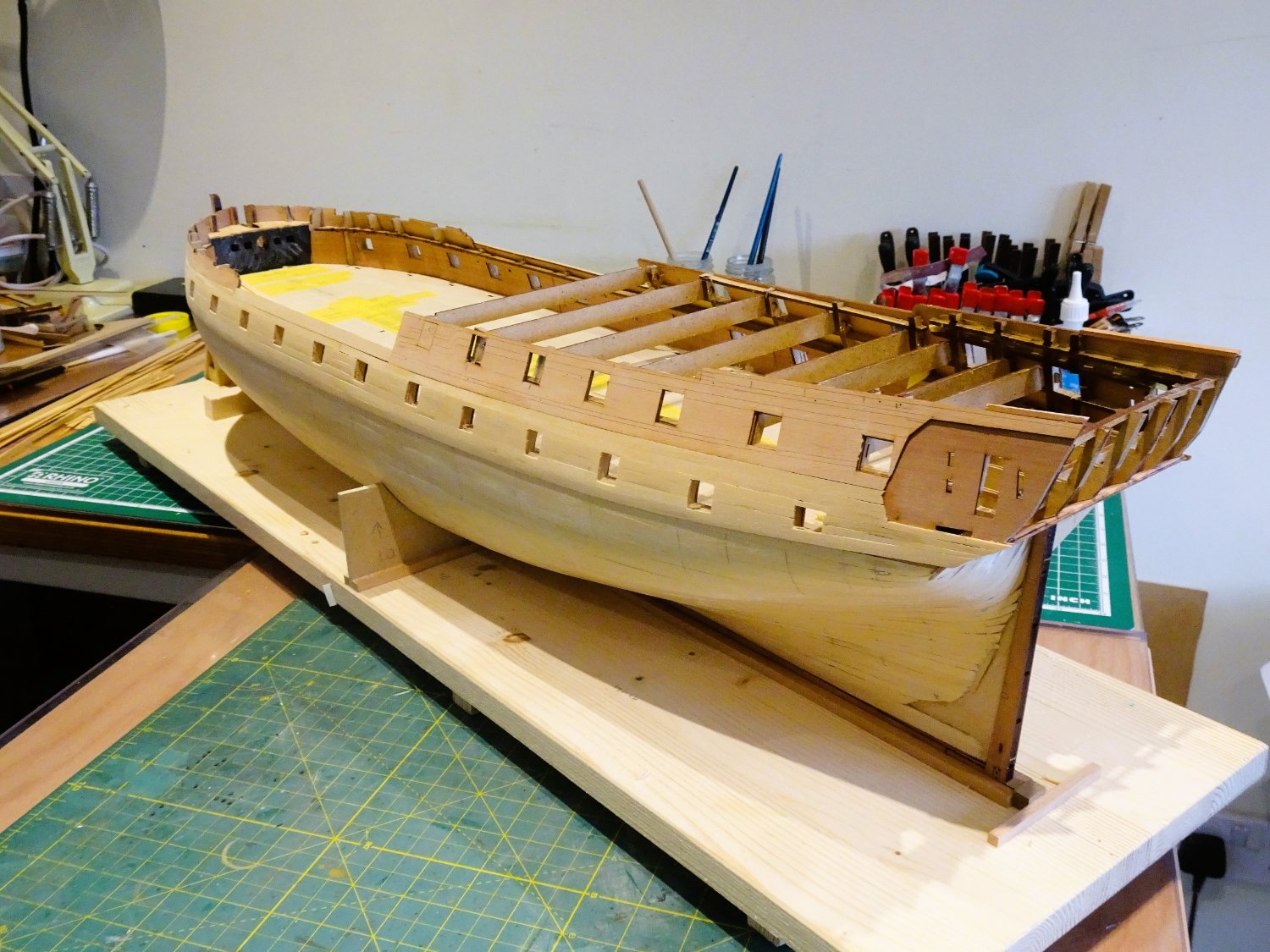
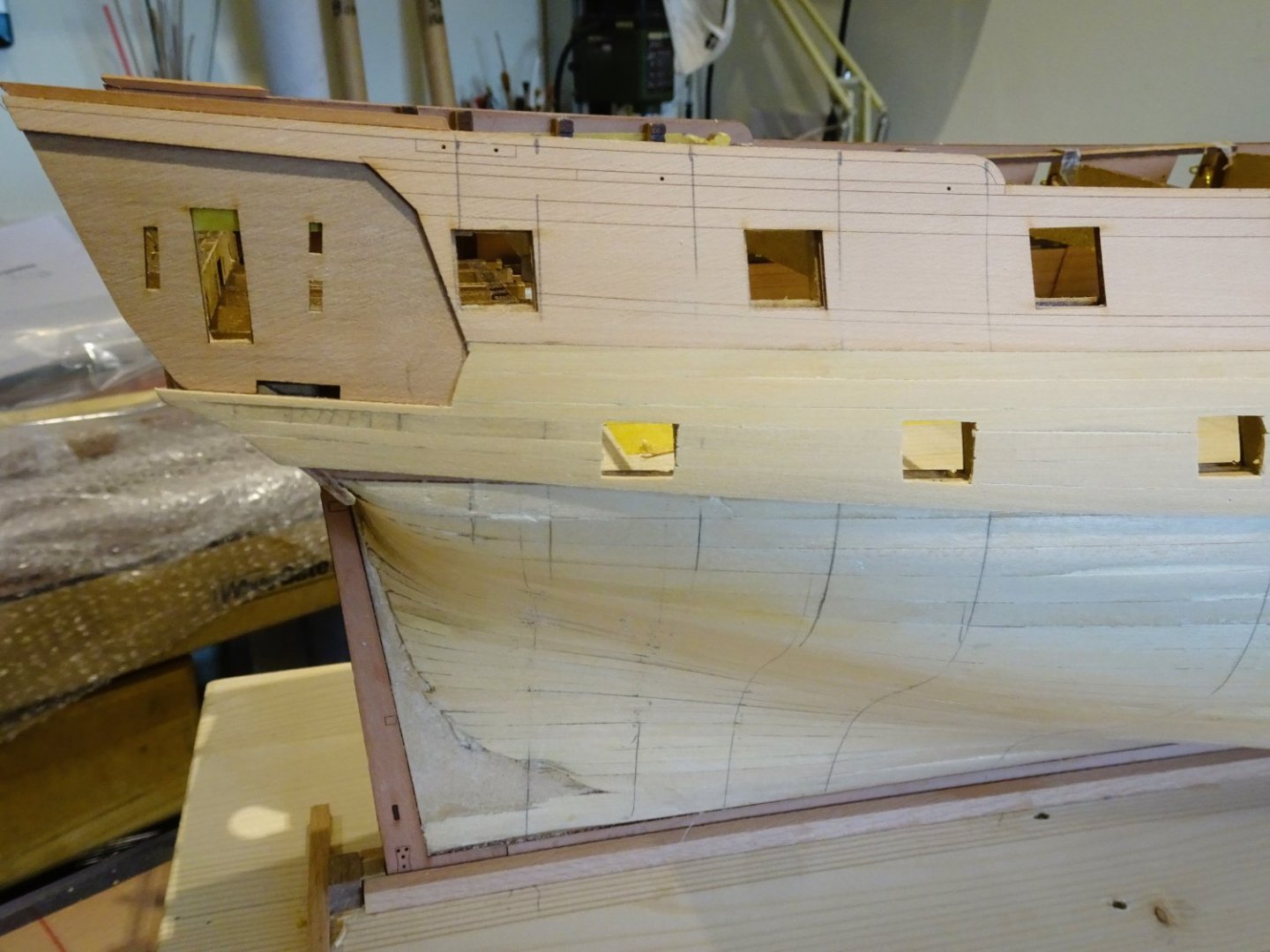
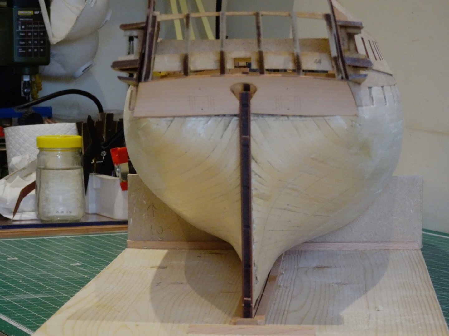
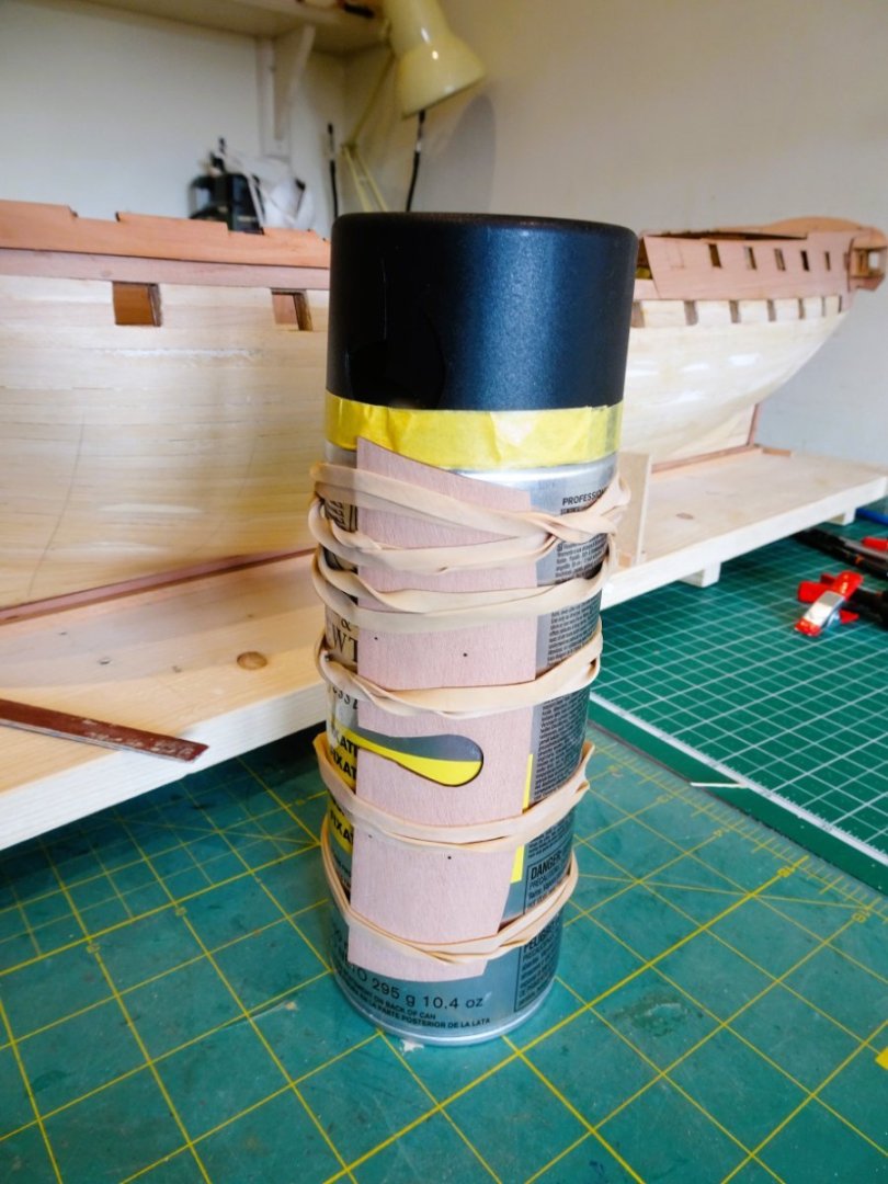
A few days away for my shipyard assistant to enjoy. 2984 Refreshed, and back at the bench. Post Twenty-five Stern and Quarter Galleries I now return to Section 165. Here Chris has ticked all my boxes, realistically constructed Quarter galleries, and correctly levelled stern bench, incorporating the rudder housing with a nice compass design on the top. Right up my Strasse and saving me a shed load of work. Even so, getting the stern gallery, Upper and lower counters, and Quarter galleries all correctly aligned is one of the most important and tricky areas of a build. In gathering together the parts for the next steps, the following is noted for clarification. Qtr Galleries. Section 174 indicates use of parts #71/72, it should read 71/73. These represent the top of the Qtr gallery (#73) and one of two layers of part #71 which form the seat of ease. Parts#72 are the bottom segments of the Qtr Gallery that slots into the hull. 888 Test fitting the Qtr Galleries. 0844 Test fitting the Poop deck. The test deck beams and deck pattern slipped seamlessly into place. 0893 There will ultimately be a lot less of Poop deck planking on my version. The next stage is that tricky business of getting the stern gallery, and upper and lower counters aligned. 0891 I used a couple of 2mm pear strips to represent the capping rails which the top of the stern gallery should meet when fitted. 0900 I found I did need to shape the lower edge of the Upper counter to fully meet the upper edge of the Lower counter. I used the lower counter as a template to match the curves. 0897 The lower counter was soaked and formed around a tin before fitting. 0904 I was in no hurry to finish this section, these parts were pinned and re-pinned several times before I was satisfied that the stern area looked good from every angle. 0903 The planking line was then trimmed to suit. On with the show. B.E. 29/04/2023


- 648 replies
-
- 23
-
-
-
- Indefatigable
- Vanguard Models
- (and 1 more)
-
Your third photo looks to be of a French Seventy-four. You can see the double stove chimneys in the square on the Foc’sle. The photo also shows arms chests either side of the galley hatch. I never could make my mind up what those two elliptical protuberances were supposed to be on the kit. There is also a bench seat for the watch officers afore the berthing to the Main Ladderway, a very French thing, and the typical chicken coops on the Poop. This model at my local museum has a jeer capstan. Most of the ship here are British. Perhaps a captured French ship would keep it upon transfer to British service? Following capture in 1798, Spartiate was re-fitted between 1801-1803 to British standards of armaments and fittings, which was the usual practice. It is impossible to know whether any French prizes retained any fittings, but removing moulded in fittings on a plastic kit is difficult, and maybe best left alone, unless they are to be covered by something else. Hmmm… if I were to cut off the jeer capstan what would go in that space? I see what looks like the stove chimney here. I suppose you could change the jeer capstan into a chimney – it’s almost there already, remove the little stove pipes, and board over the area. Regards, B.E.
-
I will be be simply using wipe-on-poly, does it for me. B.E.
- 443 replies
-
- 5
-
-
- Indefatigable
- Vanguard Models
- (and 1 more)
-
Not necessarily a strange omission, remember it’s a French ship you’re basing your model on. What would be strange is the inclusion of a Fore Jeer Capstan on a British ship, they were common on French ships of the period. That strange erection on the Fore deck abaft the fore mast is the jeer capstan. B. E.
-
The port side looks good to my eye now completed, I like the clean line you’ve achieved at the stem. Any oddly shaped planks below the round of the hull won’t have any visual impact on the display, I usually end up with one on my efforts. On with the show Kevin. 👍 B.E.
- 443 replies
-
- 6
-
-
- Indefatigable
- Vanguard Models
- (and 1 more)
-
That thought fills me with horror, the amount of planking you get thro' and the excellent results you achieve with the proto builds, I just couldn't live with the pace of it. Chris has got the right man. @ Alistair - send me the air fare, I'll be there .😉 B.E.
- 648 replies
-
- 4
-

-
-
- Indefatigable
- Vanguard Models
- (and 1 more)
-
Hello Joe, thanks for looking in on my build. Kevin has provided a link to a planking guide, which is a good place to start. In addition, if you go into the Articles database at the top of the ribbon you will find a copy of the planking fan contained within Chuck Passaro’s article as below, and an excellent guide how to use it. Lining Off your hull for planking (thenrg.org) Scroll down to the Framing and planking section, there is a wealth of advice to be had. Regards, B.E.
- 648 replies
-
- 3
-
-
- Indefatigable
- Vanguard Models
- (and 1 more)
-
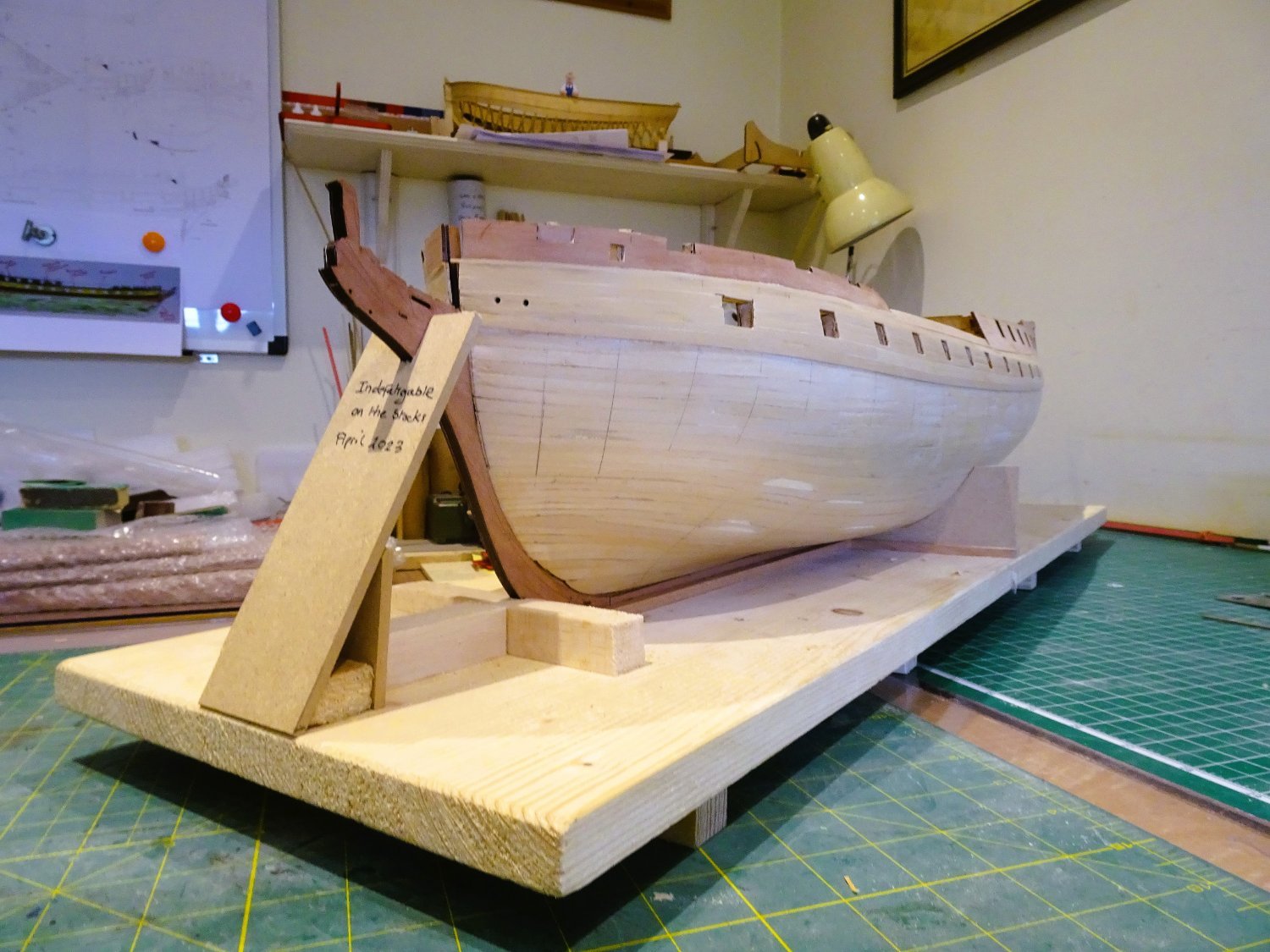
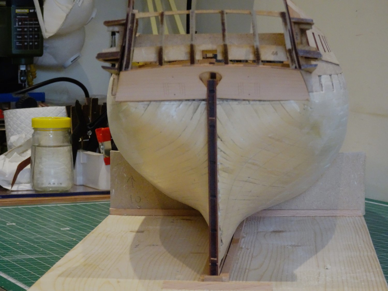
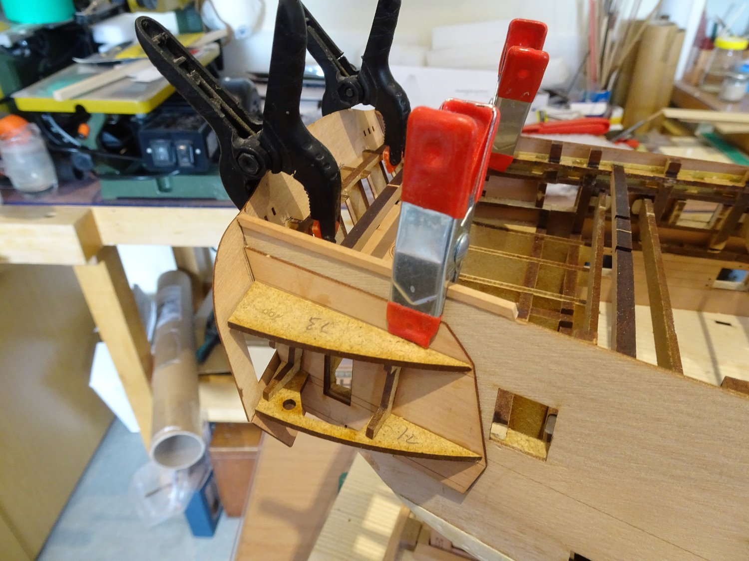
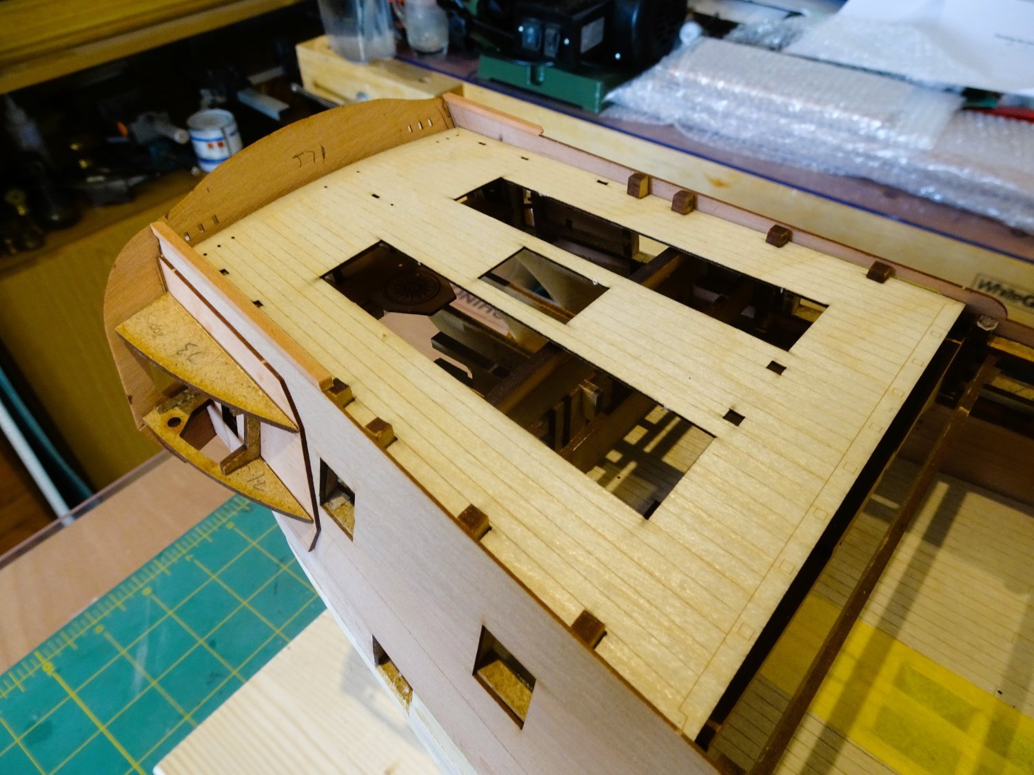
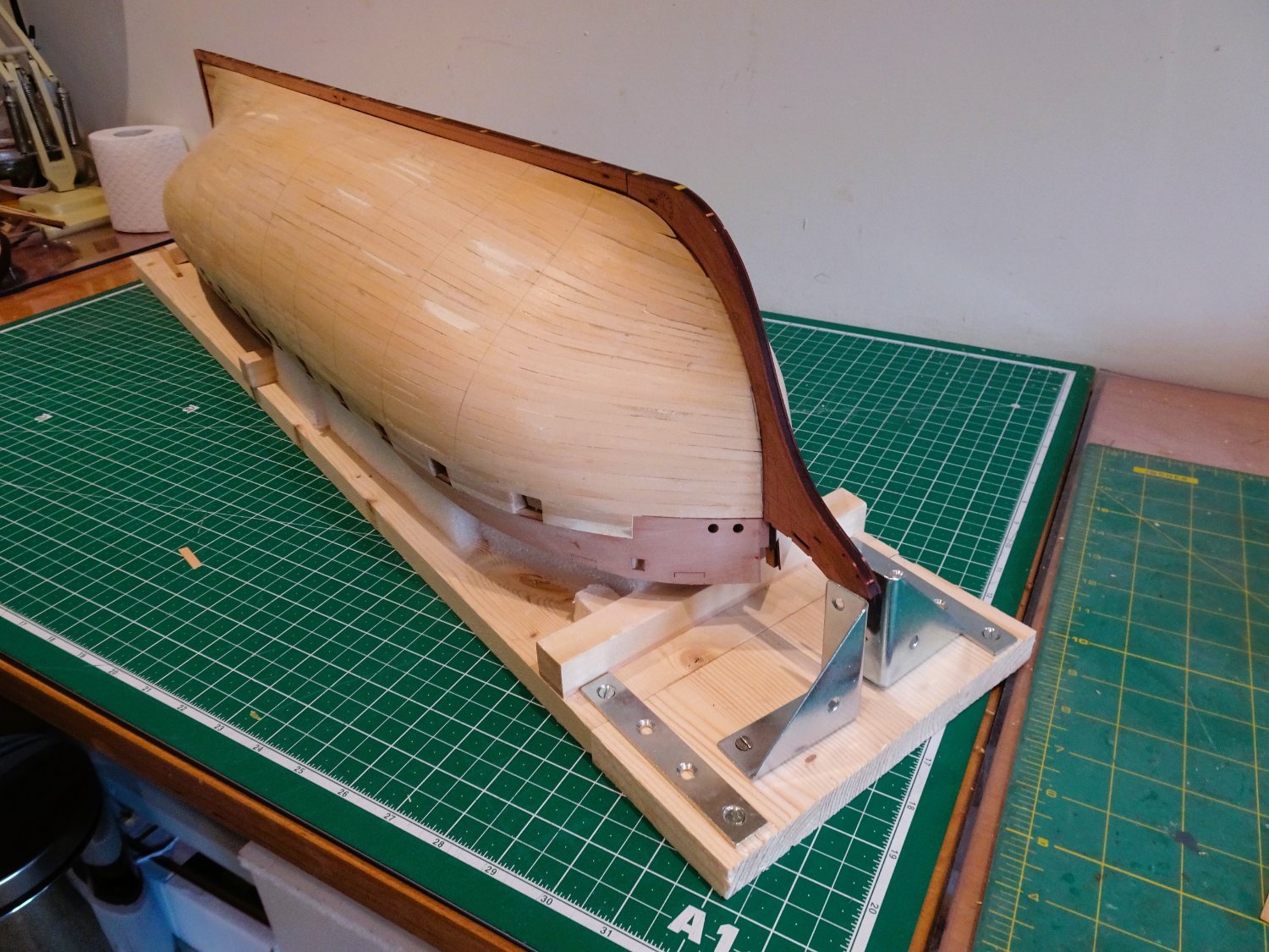
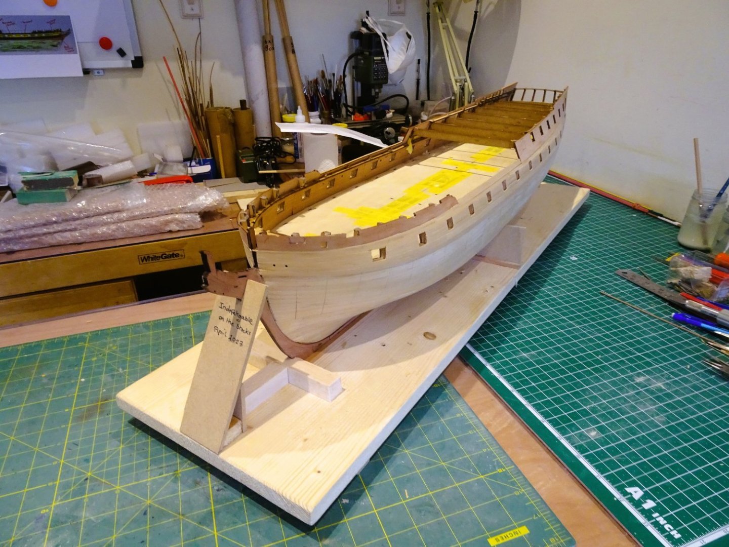
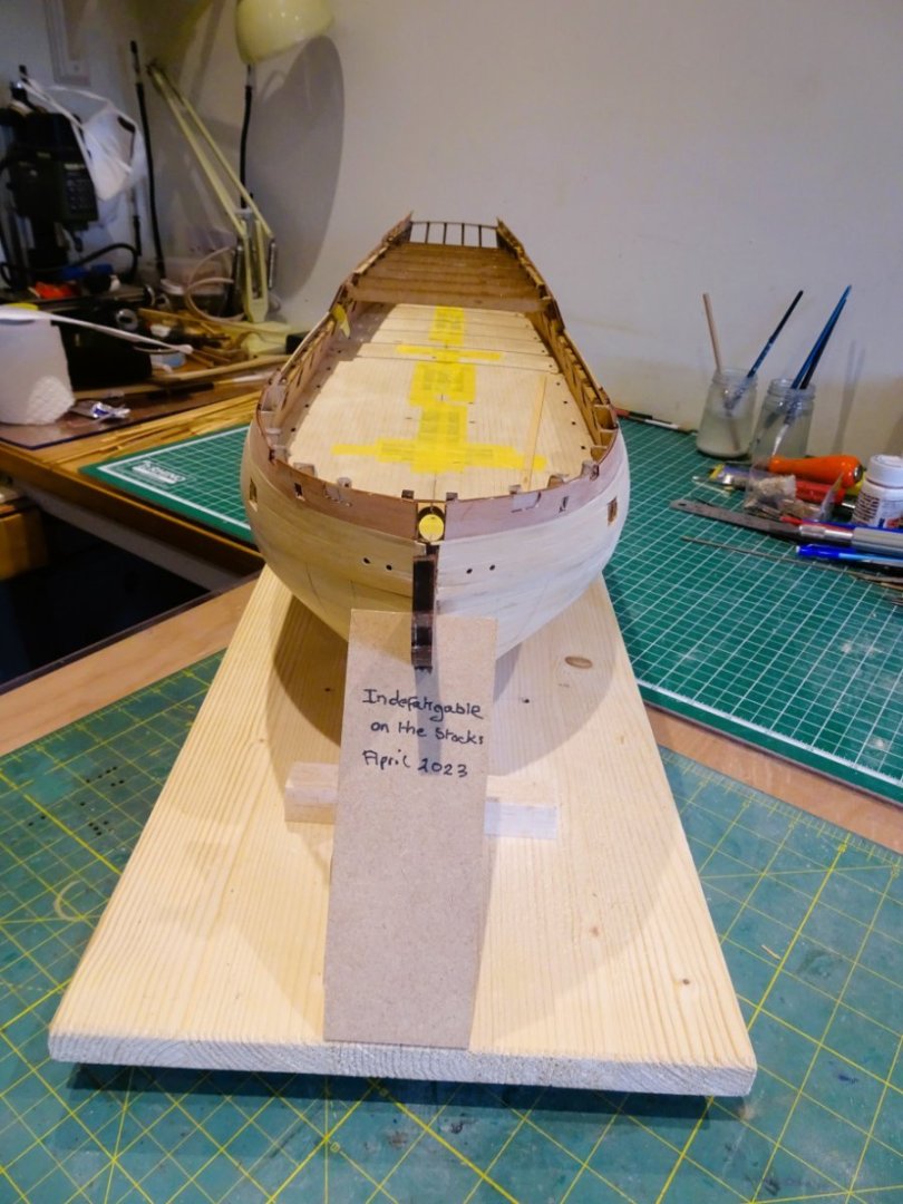
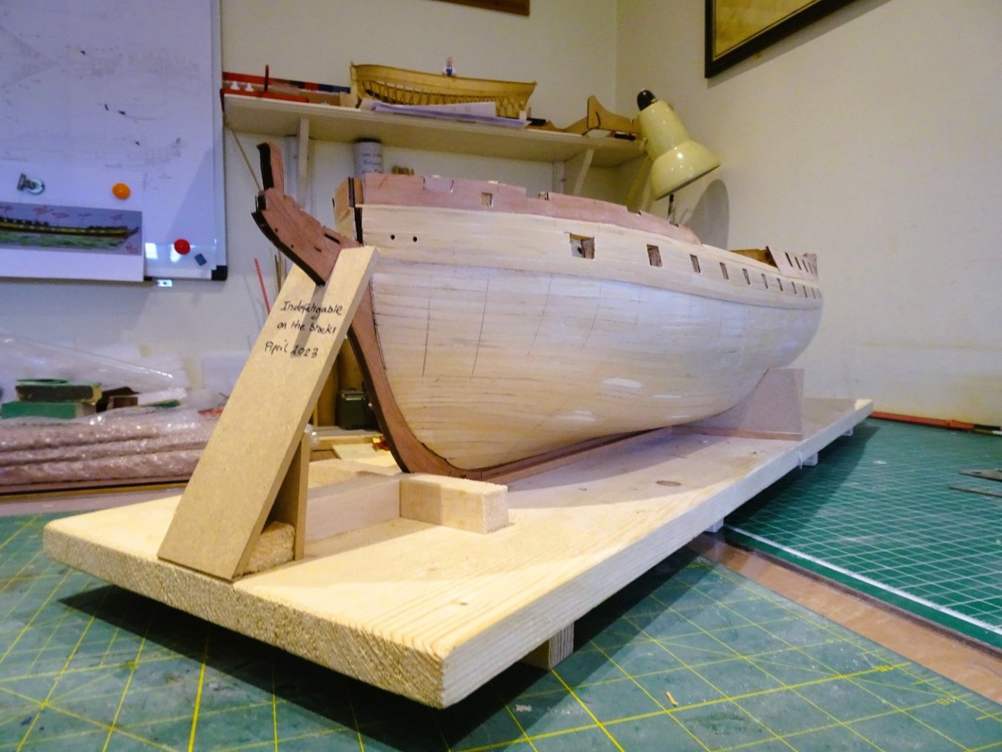
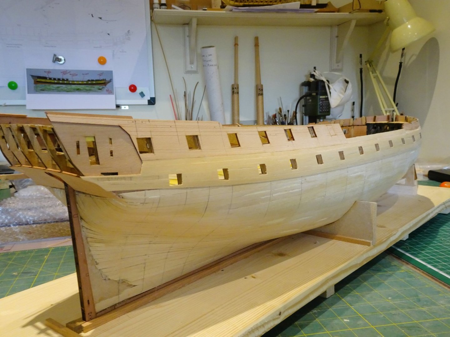
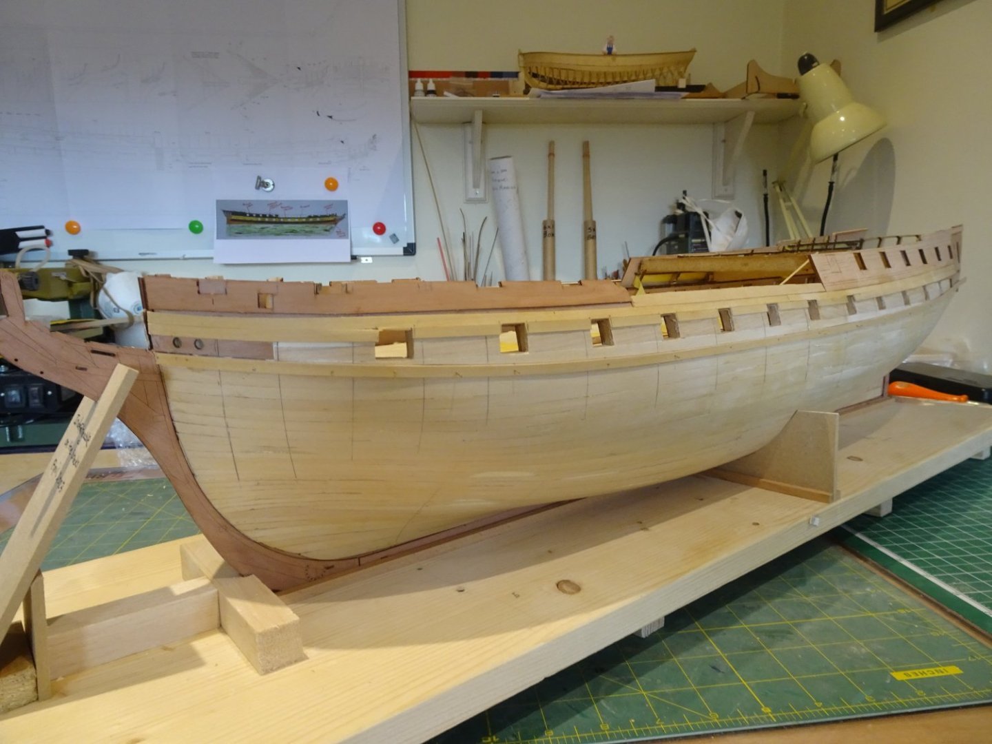
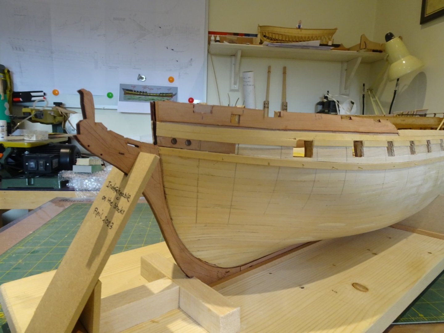
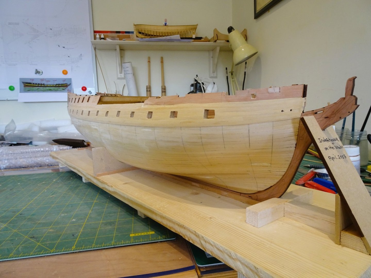
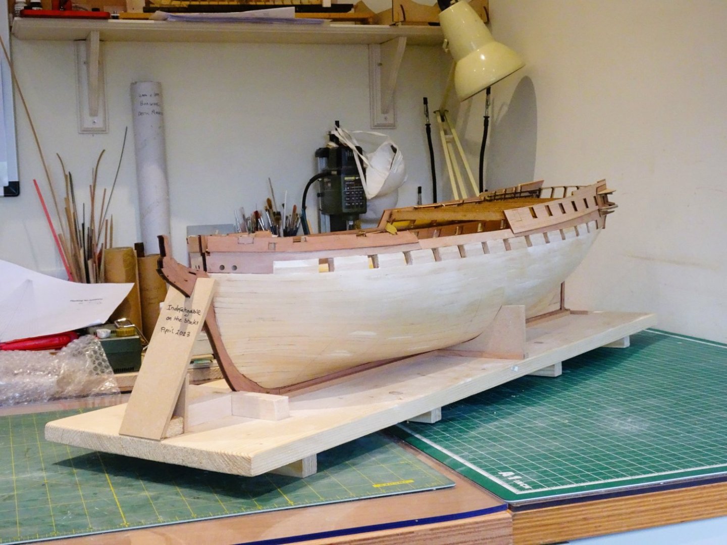
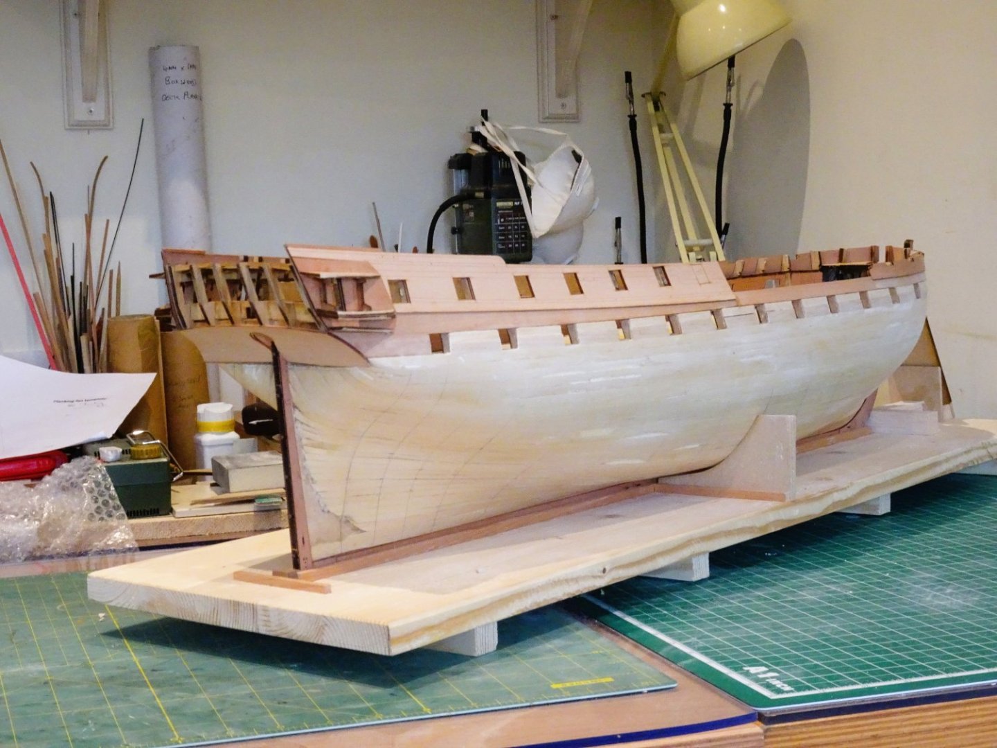
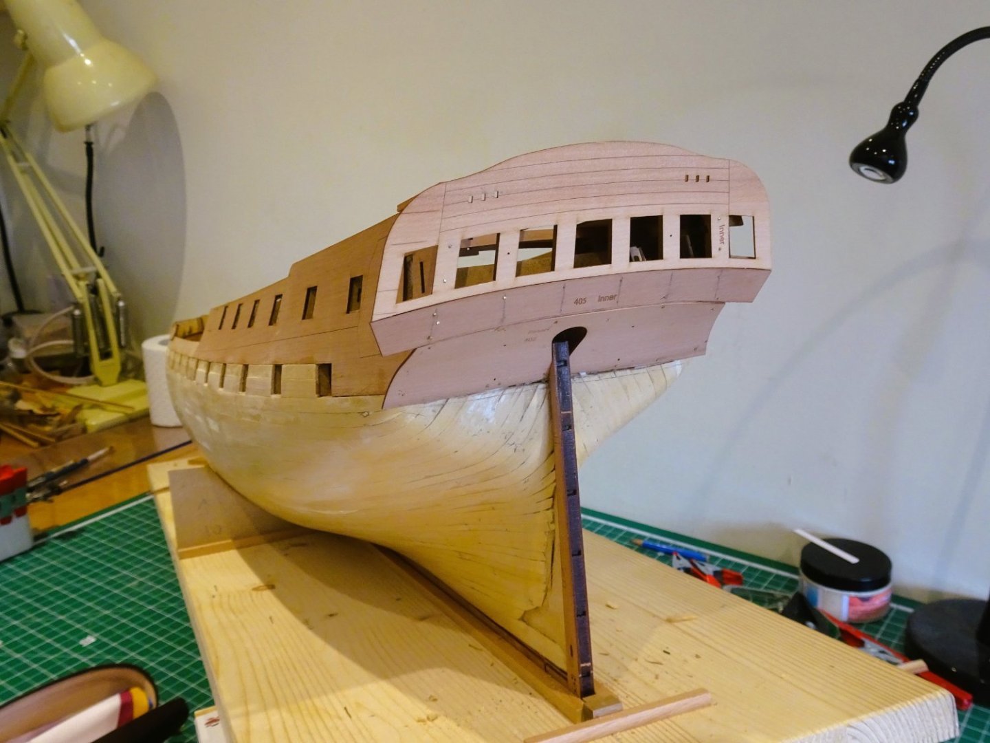
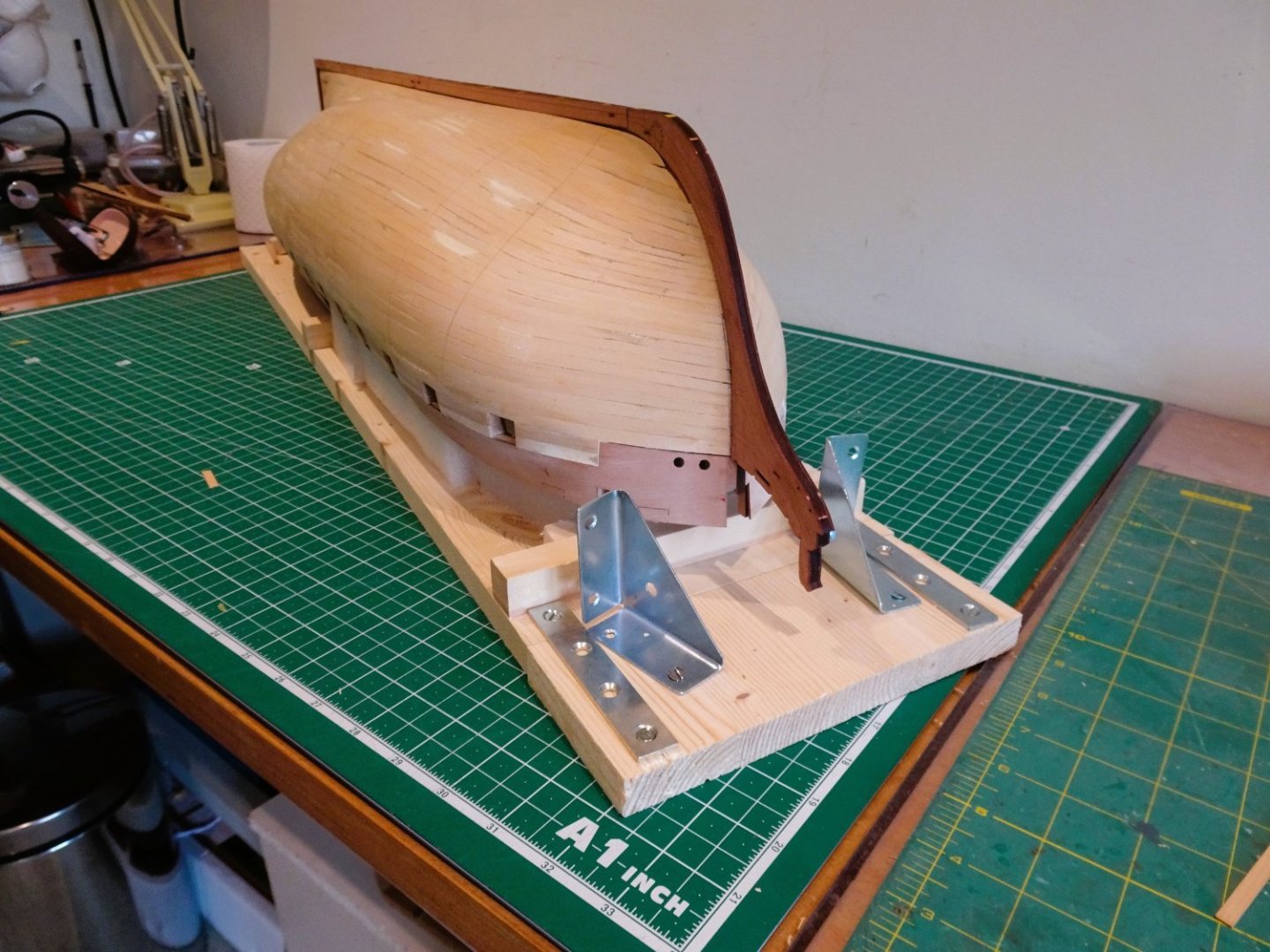
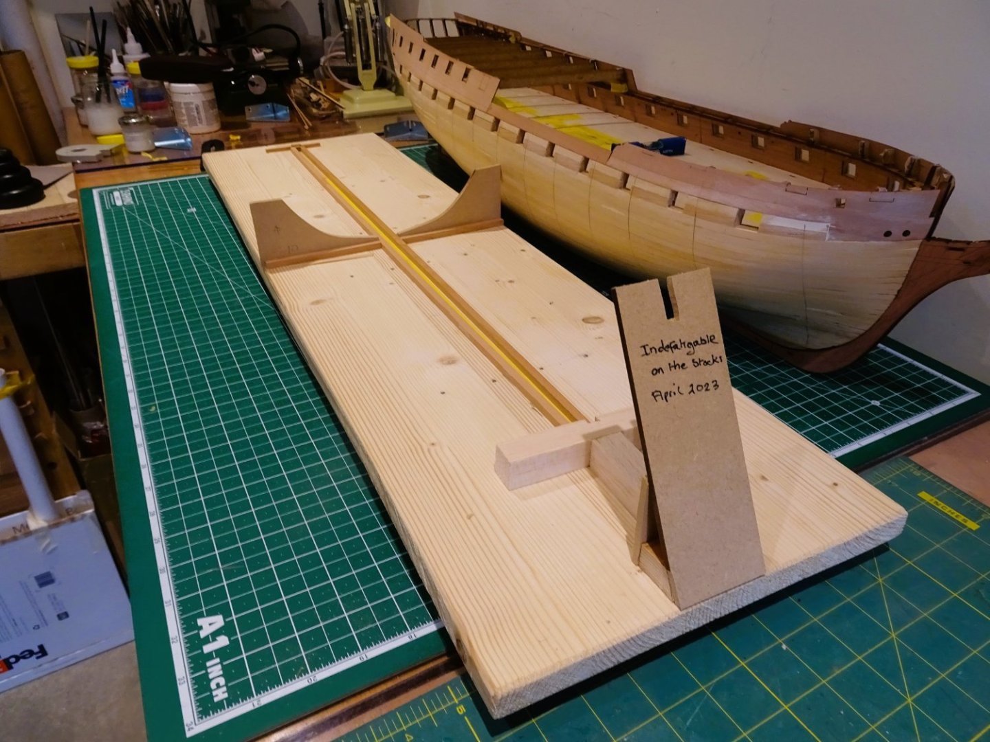
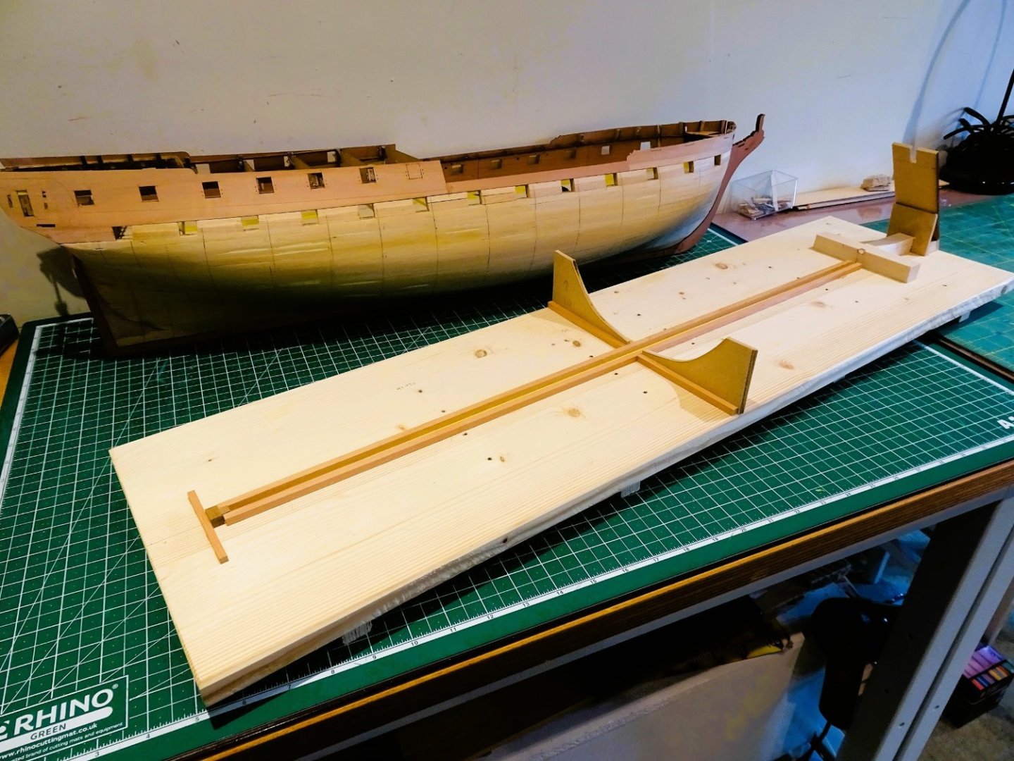
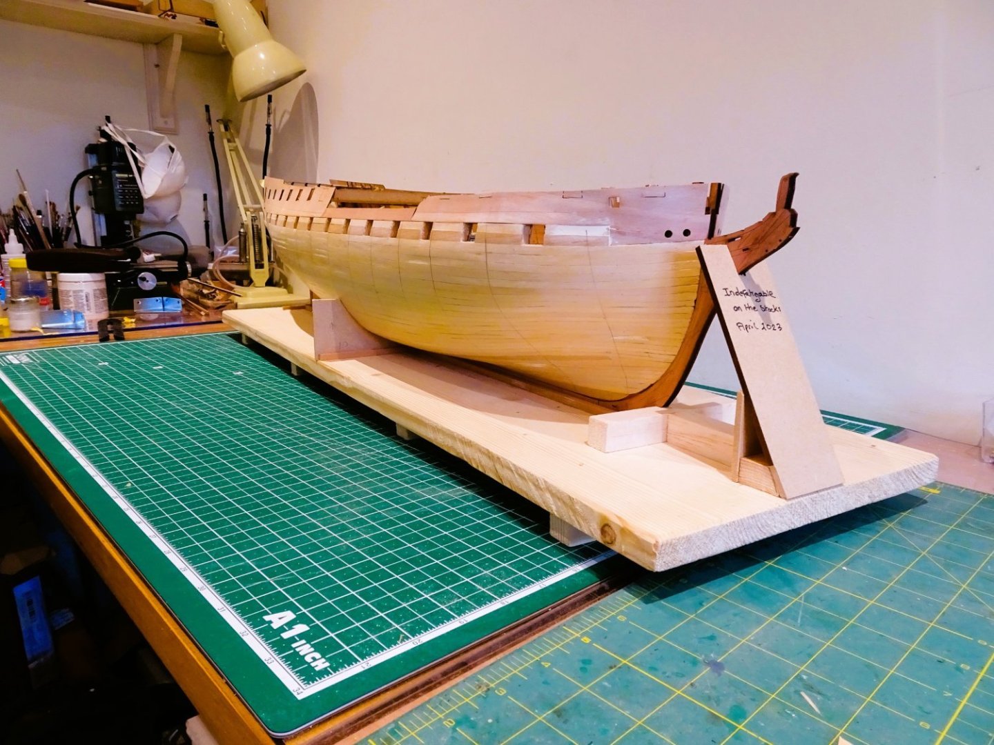
Post Twenty-four At this point I skip sections 165-191 and move to fit the keel, stem, and sternpost pieces. I want the keel pieces in place to modify the build board for the upright hull which will be used for most of the fitting out and detailing. All these pieces fit together nicely. Note: The keel facings are numbered 437/439 (Fore) and 438/440 (stern) – not as shown in the manual. The pieces are port and starboard specific. 0832 I found the trickiest part was fitting the stem facings. I needed to further tweak the planks ends using a micro chisel to allow the facing pieces to sit flat against the stem at all points, and line up with the peg slots. The hull will remain inverted for hull planking and that board has been modified to protect the vulnerable stem piece. 0833 0835 The stem protectors can be swung in and out of position. It would be a tricky issue if the delicate figure seating at the prow was to be broken off. 0840 0841 The upright building board has now been modified to support the planked hull. 0842 0838 Indy is now secure and sitting level, I don’t want this beast moving around whilst I am working on her. On with the show. B.E. 19/04/2023

- 648 replies
-
- 25
-
-
- Indefatigable
- Vanguard Models
- (and 1 more)
-
I'm not prepared to risk it Jason, it also has implications for the keel. Knowing when not to meddle is a valuable skill in our business.😉 Cheers, B.E.
- 648 replies
-
- 5
-
-
- Indefatigable
- Vanguard Models
- (and 1 more)
-
Glad to hear you're feeling better Hakan, hope you have a more settled 2023. I can continue to enjoy your model as she is, in frame, all that lovely woodwork, and I would be happy to display her as is. Regards, B.E.
-
I like your approach to hull planking Cisco, she's shaping up to be a very nice model. 👍 Regards, B.E.

-Copy.JPG.b5d6bc9684b3f573c16d3dd3259ff2ca.JPG)