HOLIDAY DONATION DRIVE - SUPPORT MSW - DO YOUR PART TO KEEP THIS GREAT FORUM GOING! (Only 13 donations so far - C'mon guys!)
×
.JPG.ca33079f5815b861e67b9c2cccd37982.JPG)

Blue Ensign
-
Posts
4,564 -
Joined
-
Last visited
Content Type
Profiles
Forums
Gallery
Events
Everything posted by Blue Ensign
-
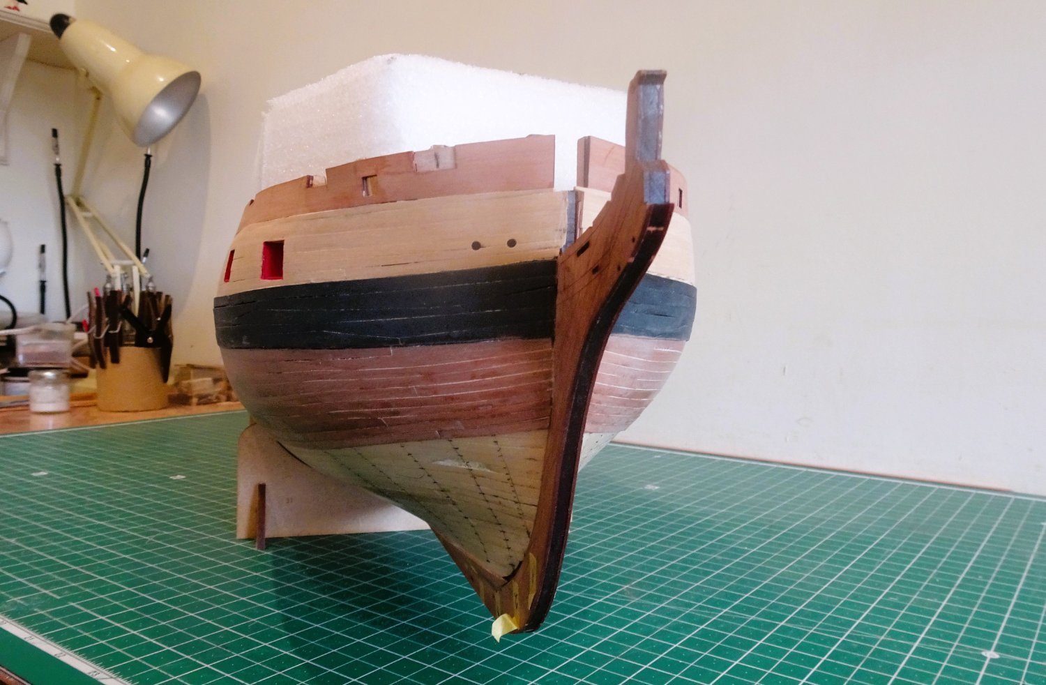
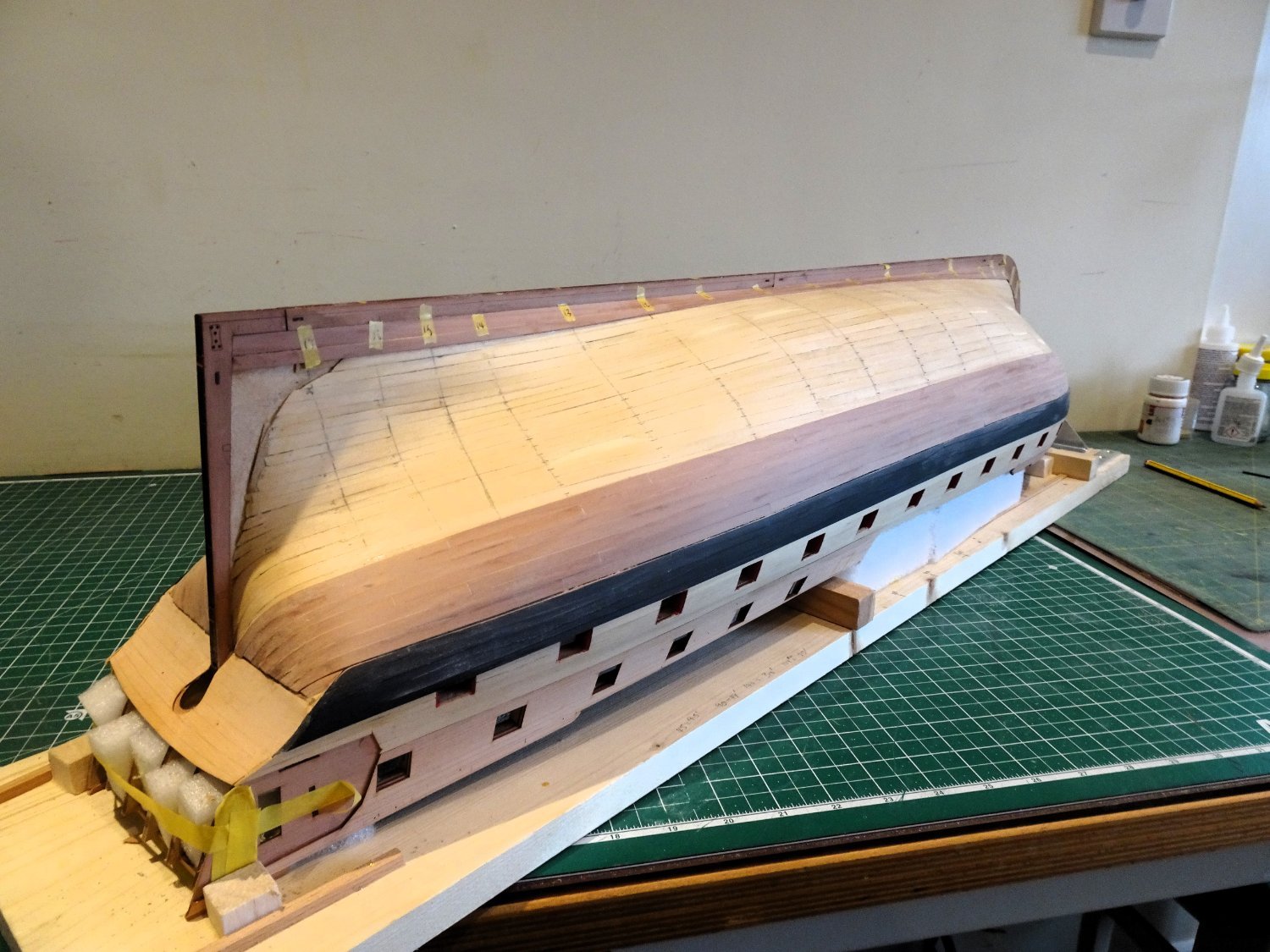
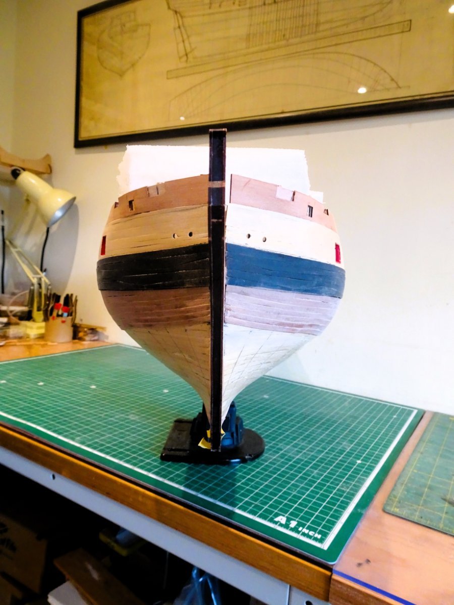
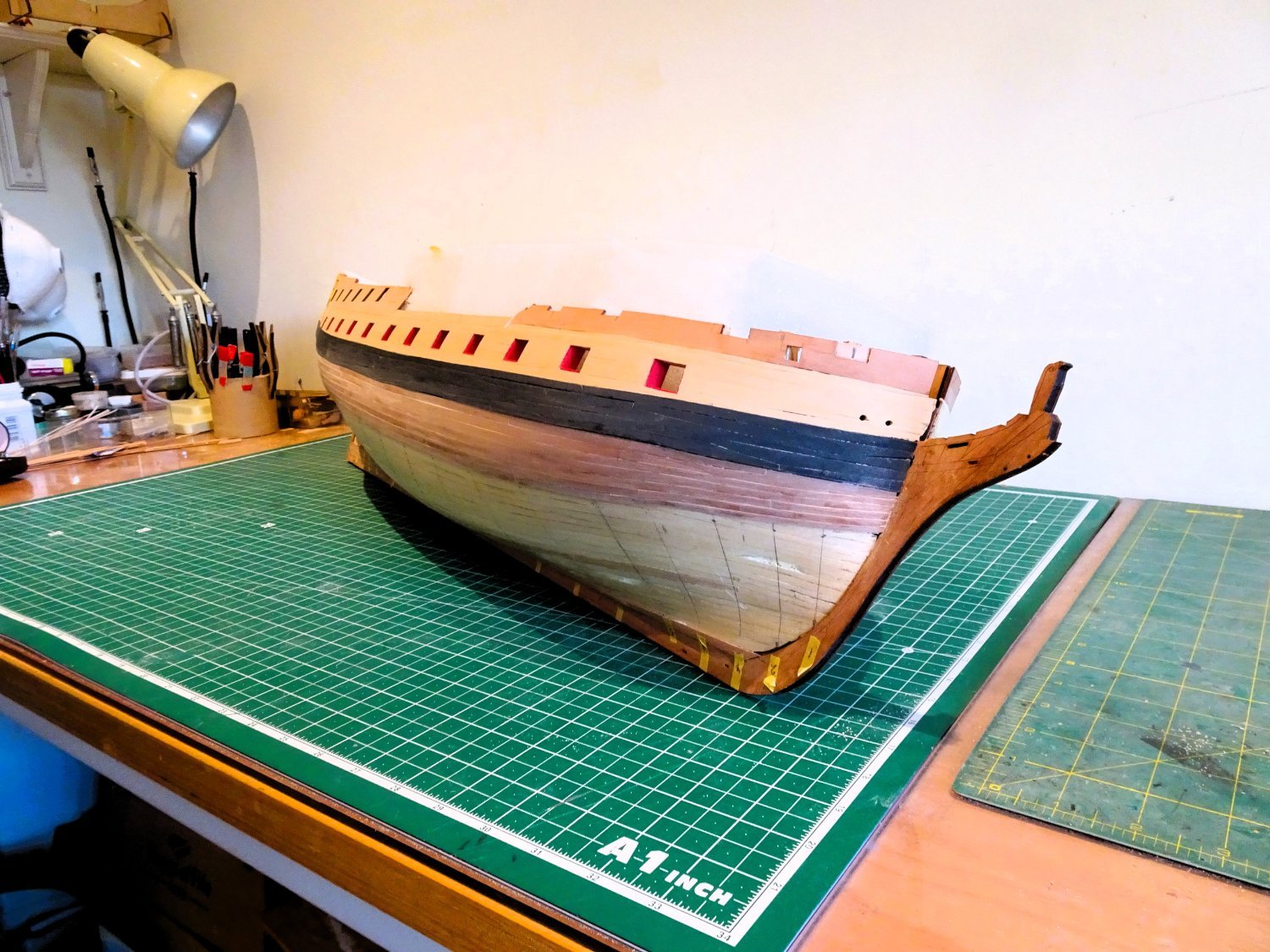
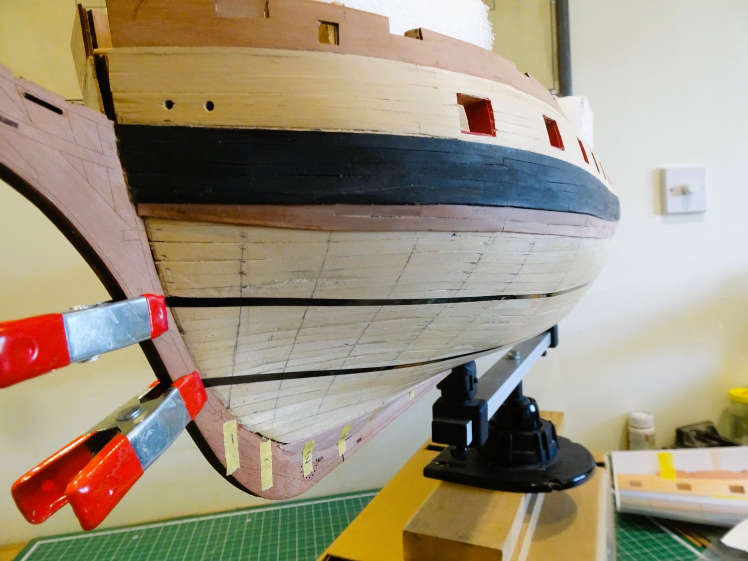
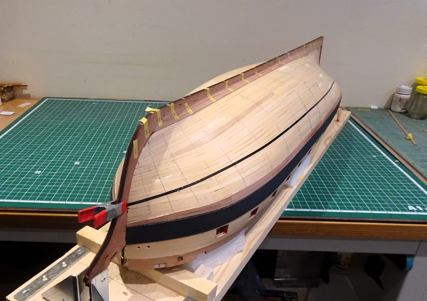
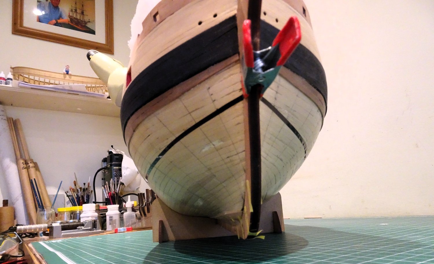
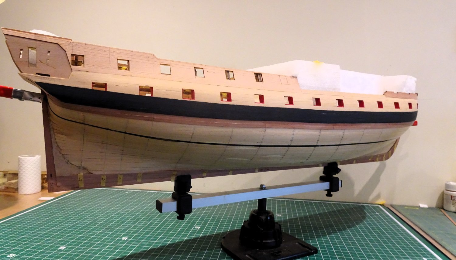
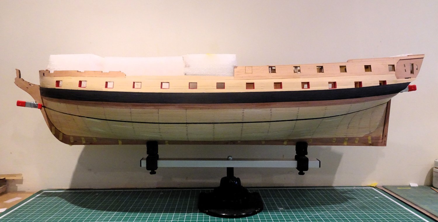
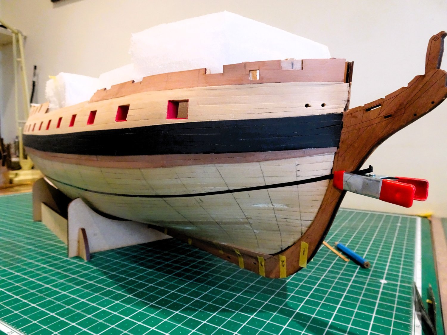
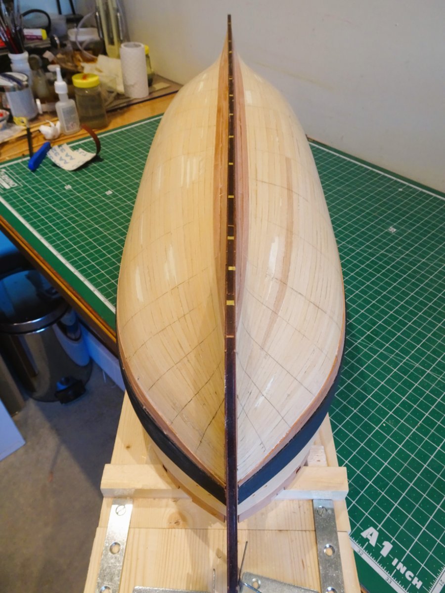
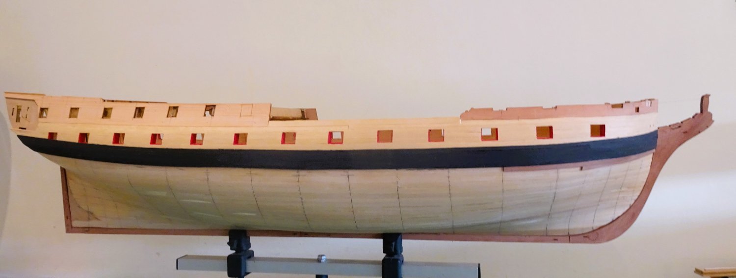
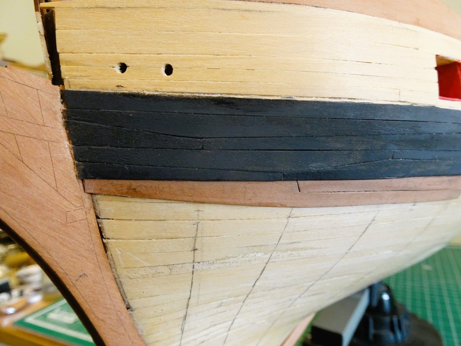
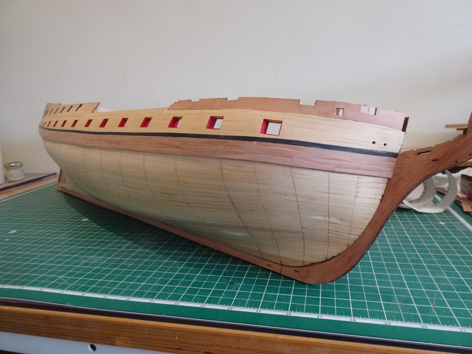
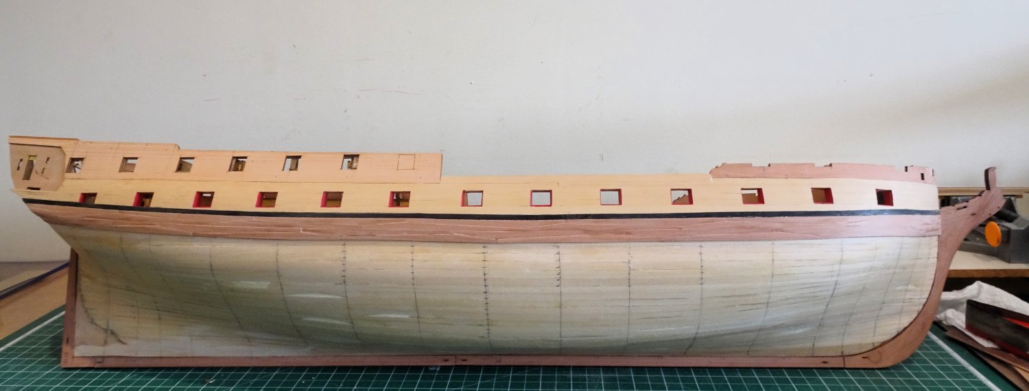
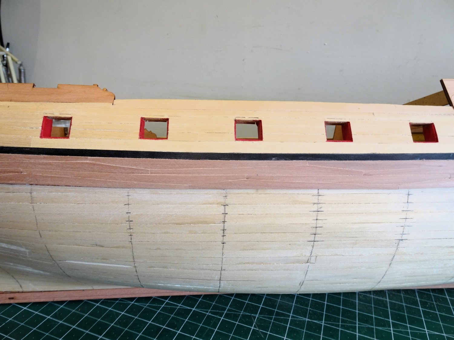
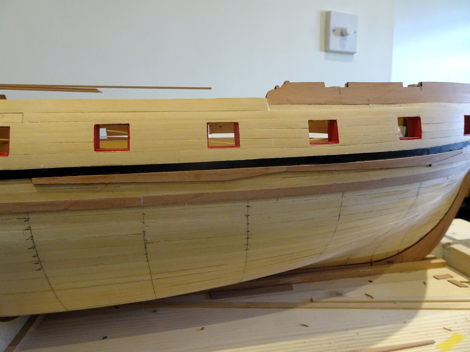
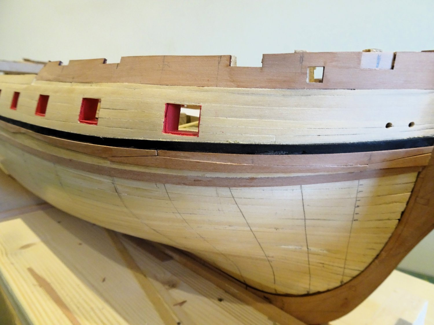
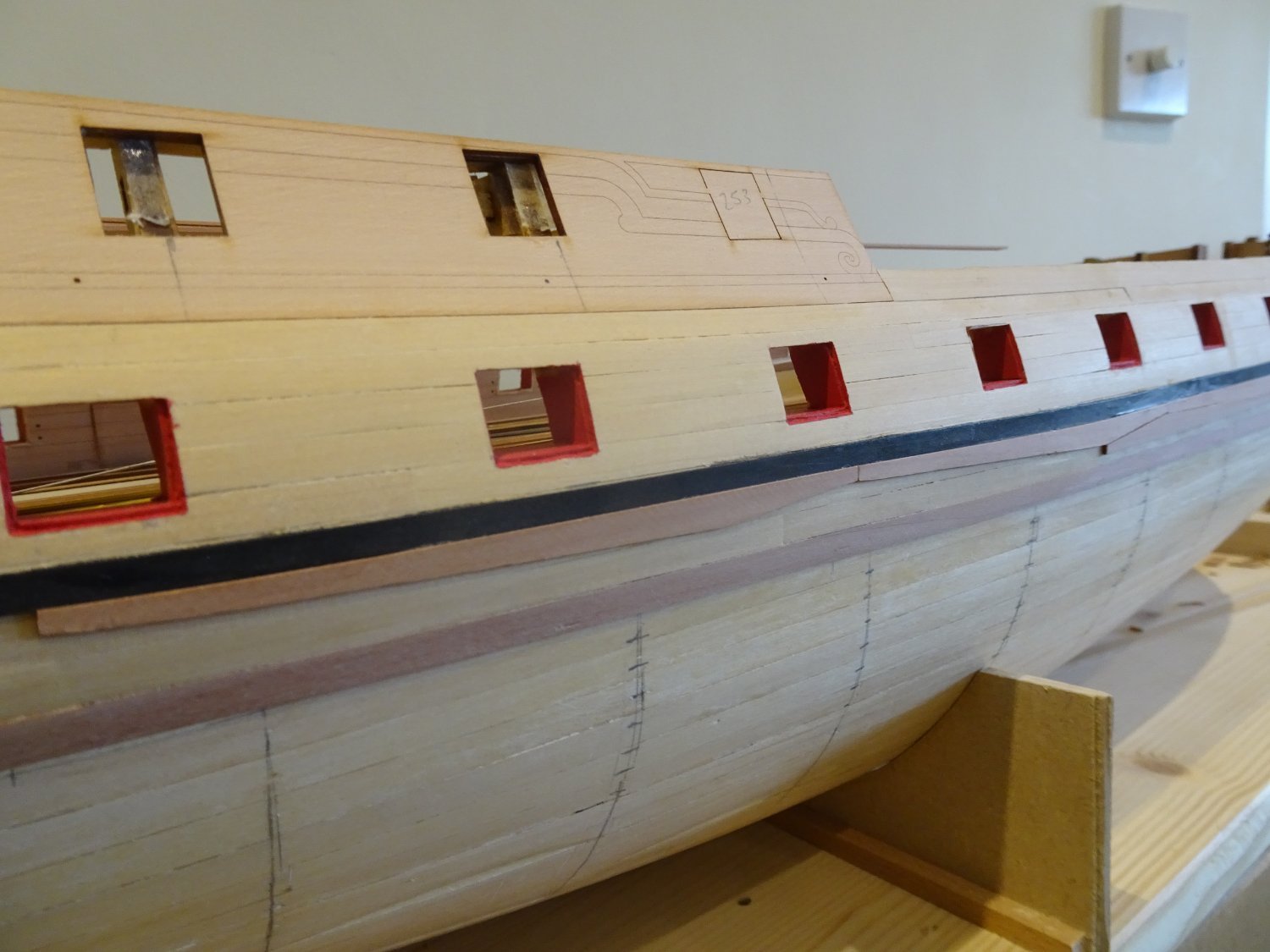
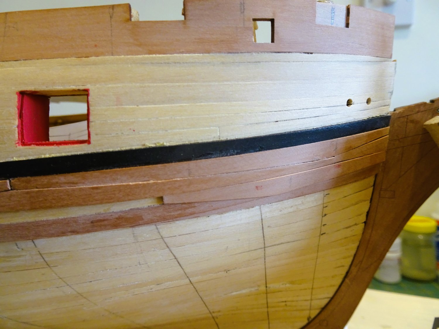
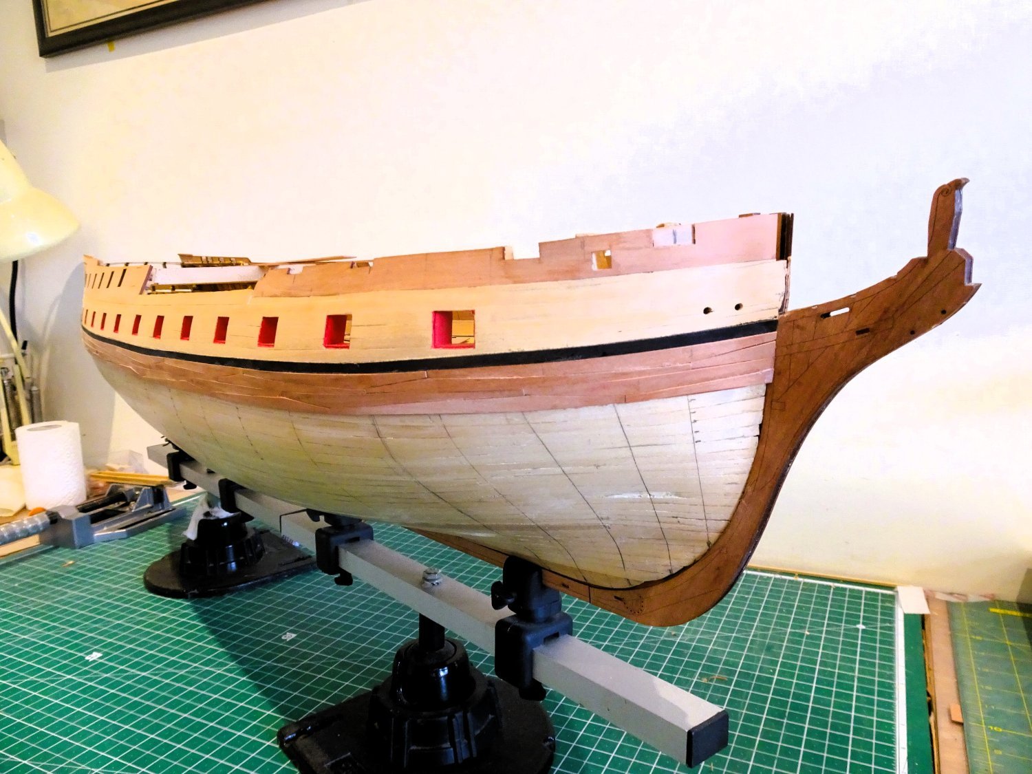
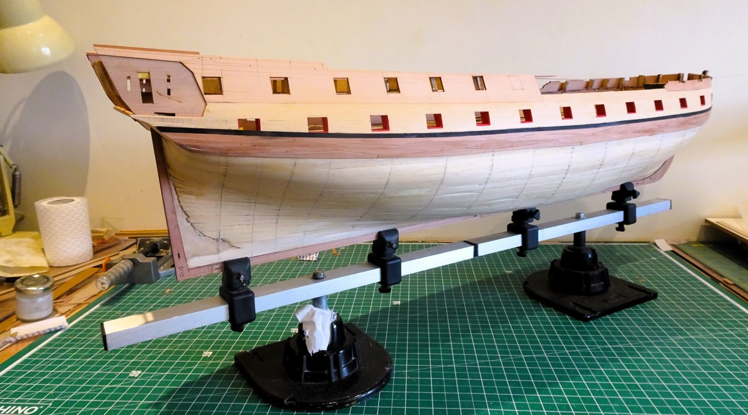
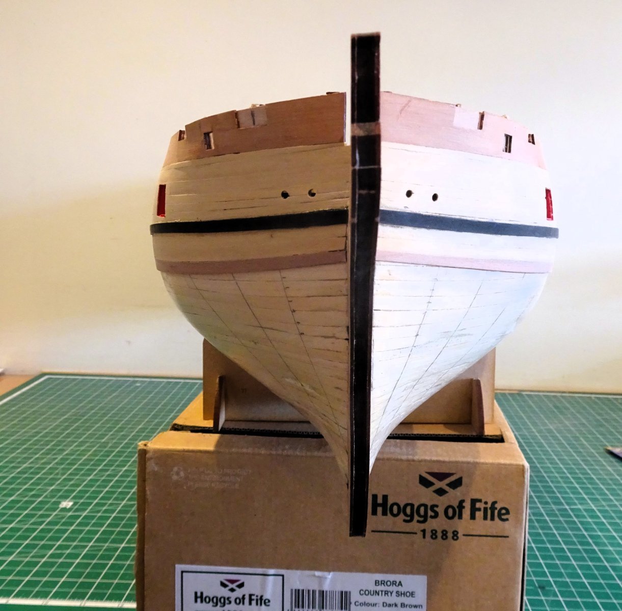
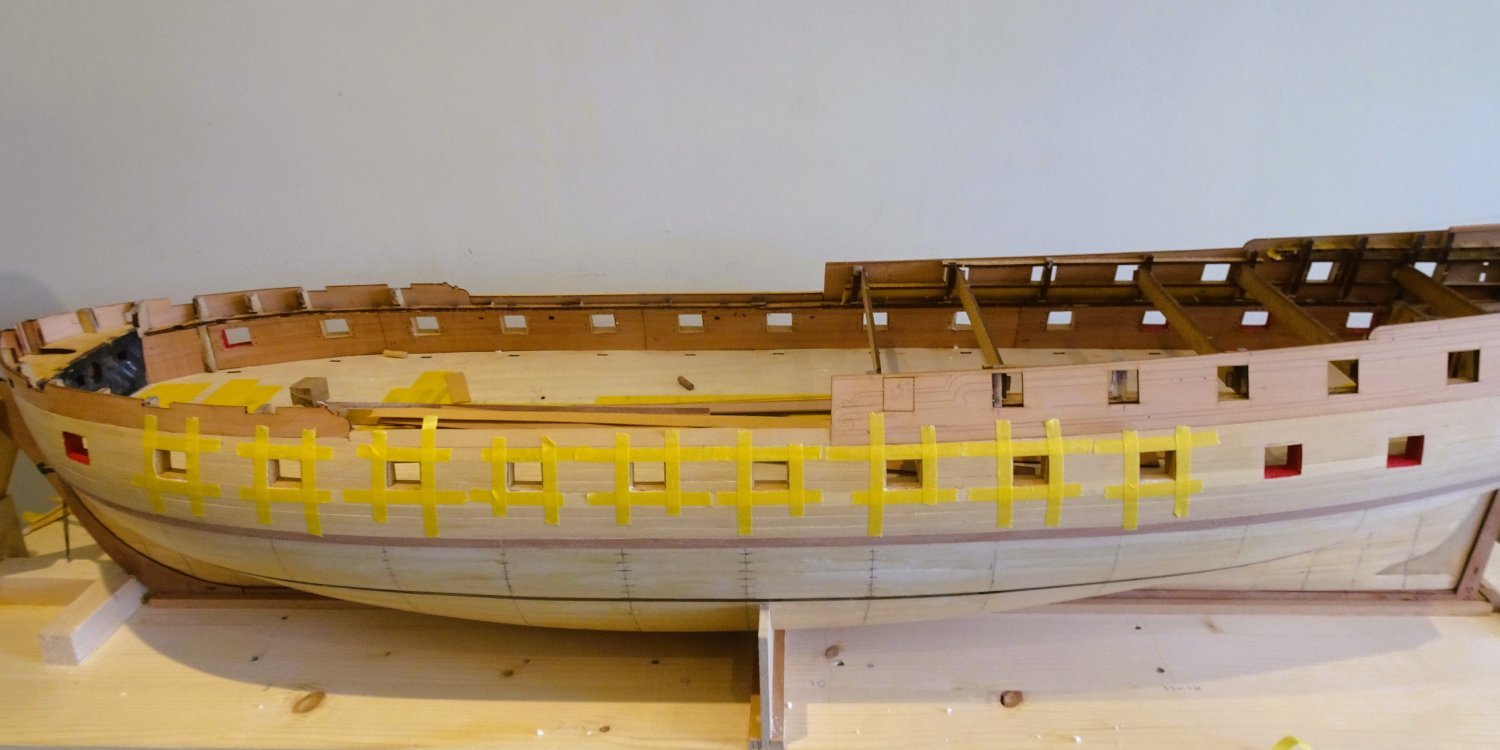
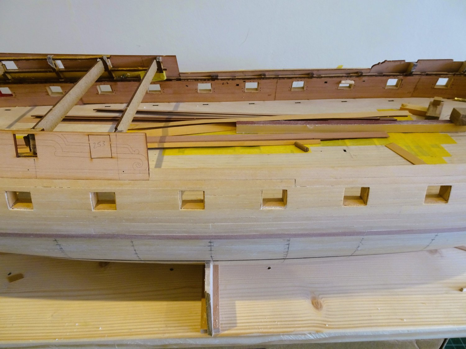
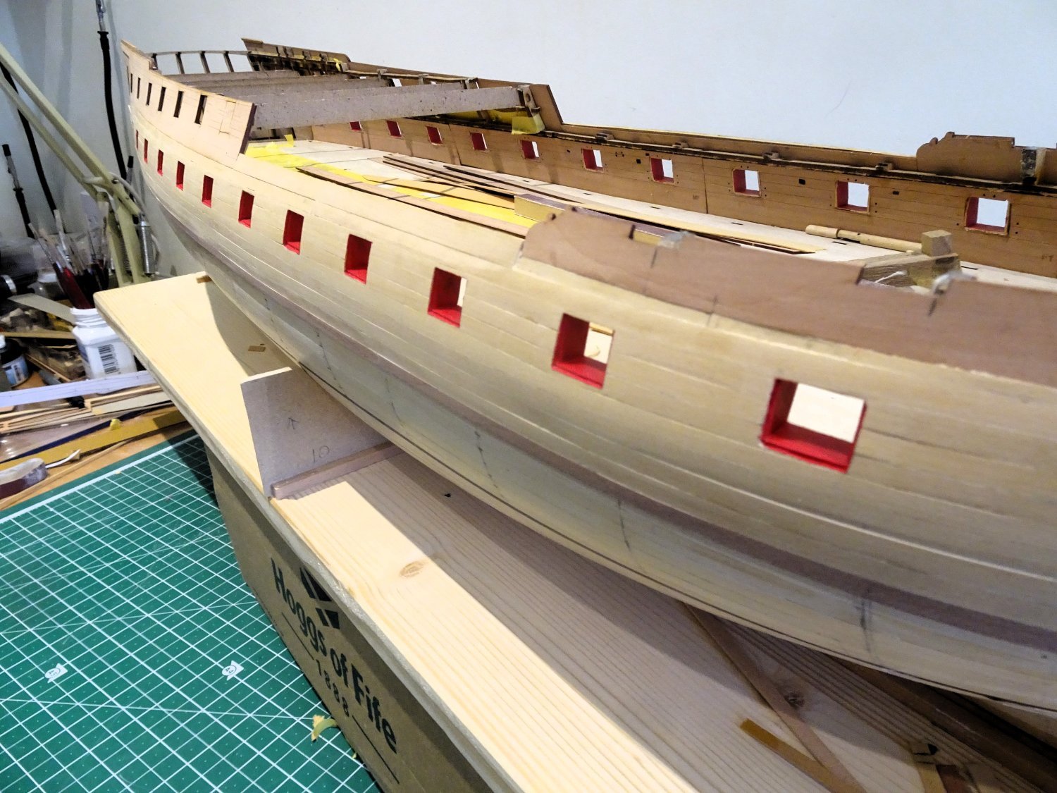
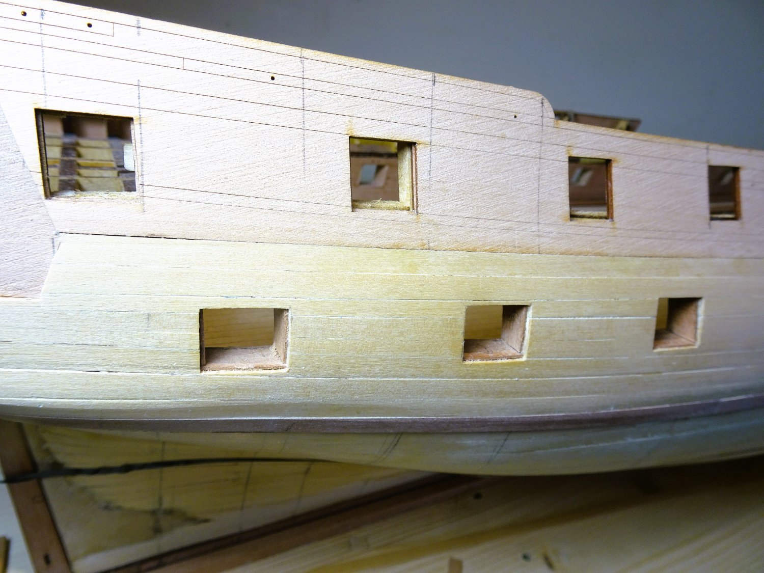
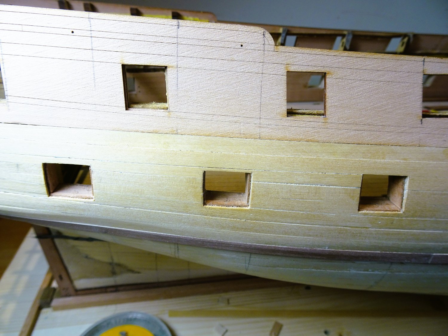
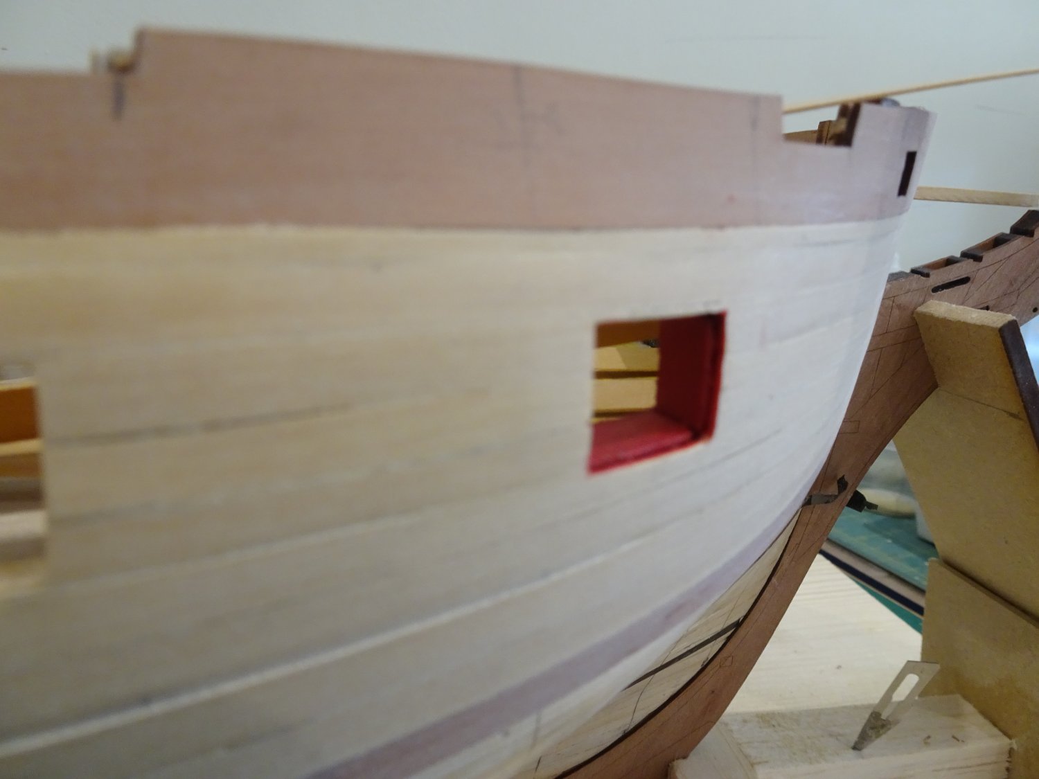
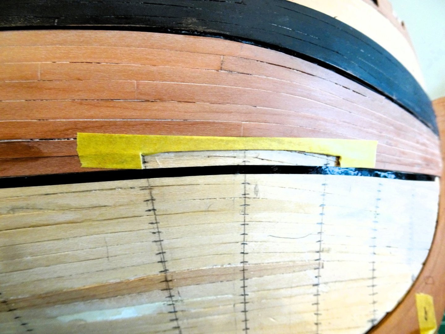
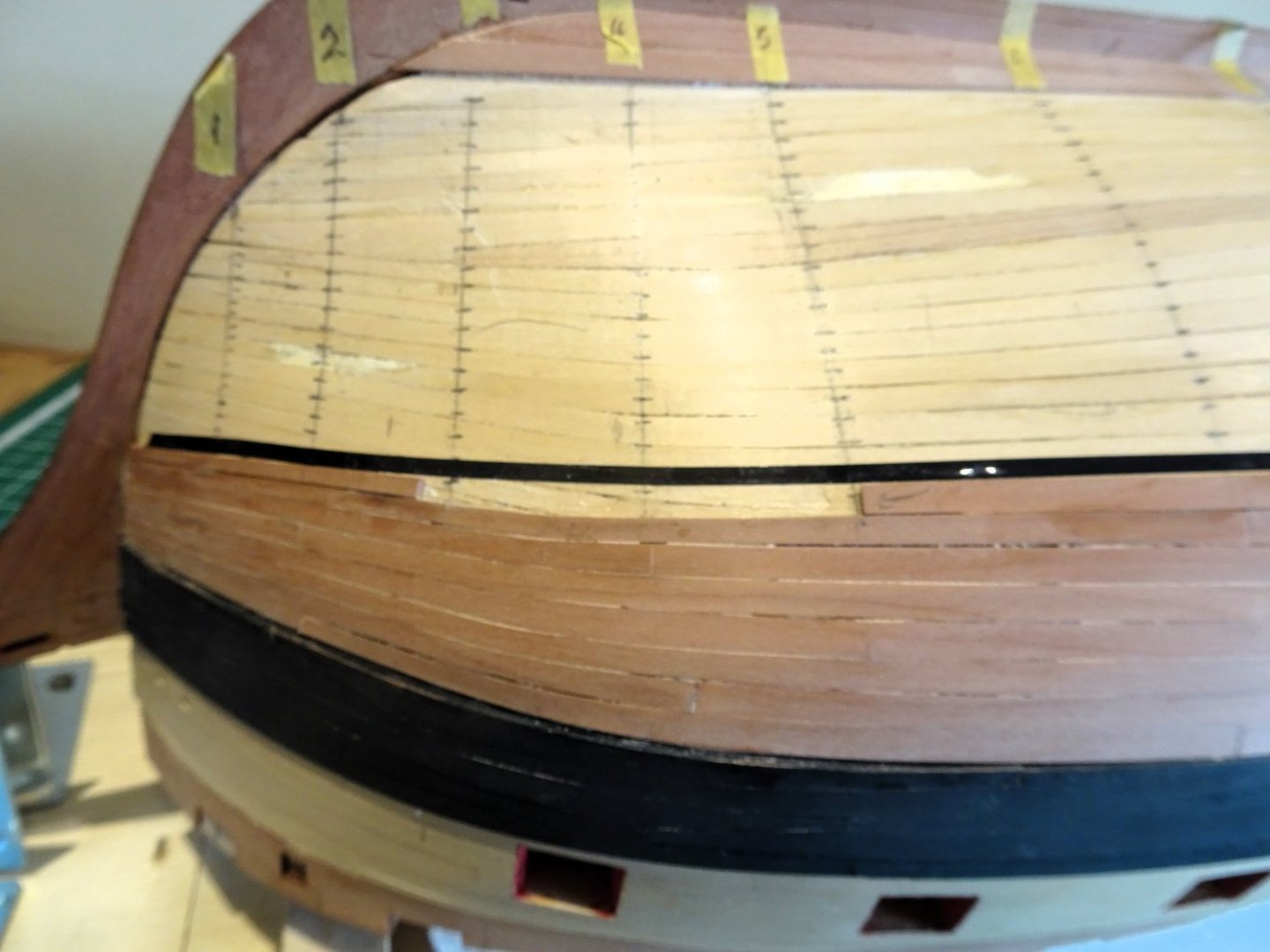
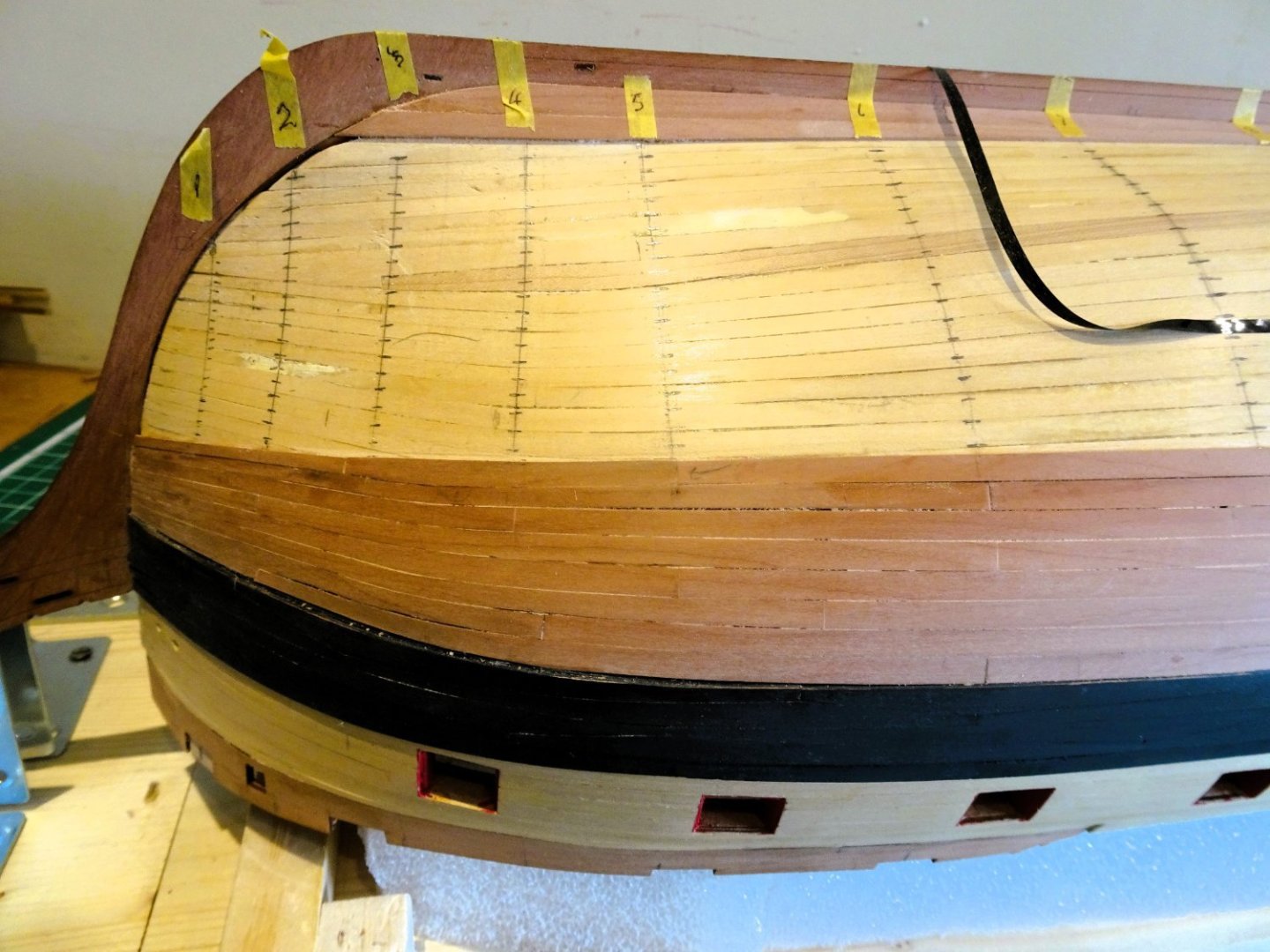
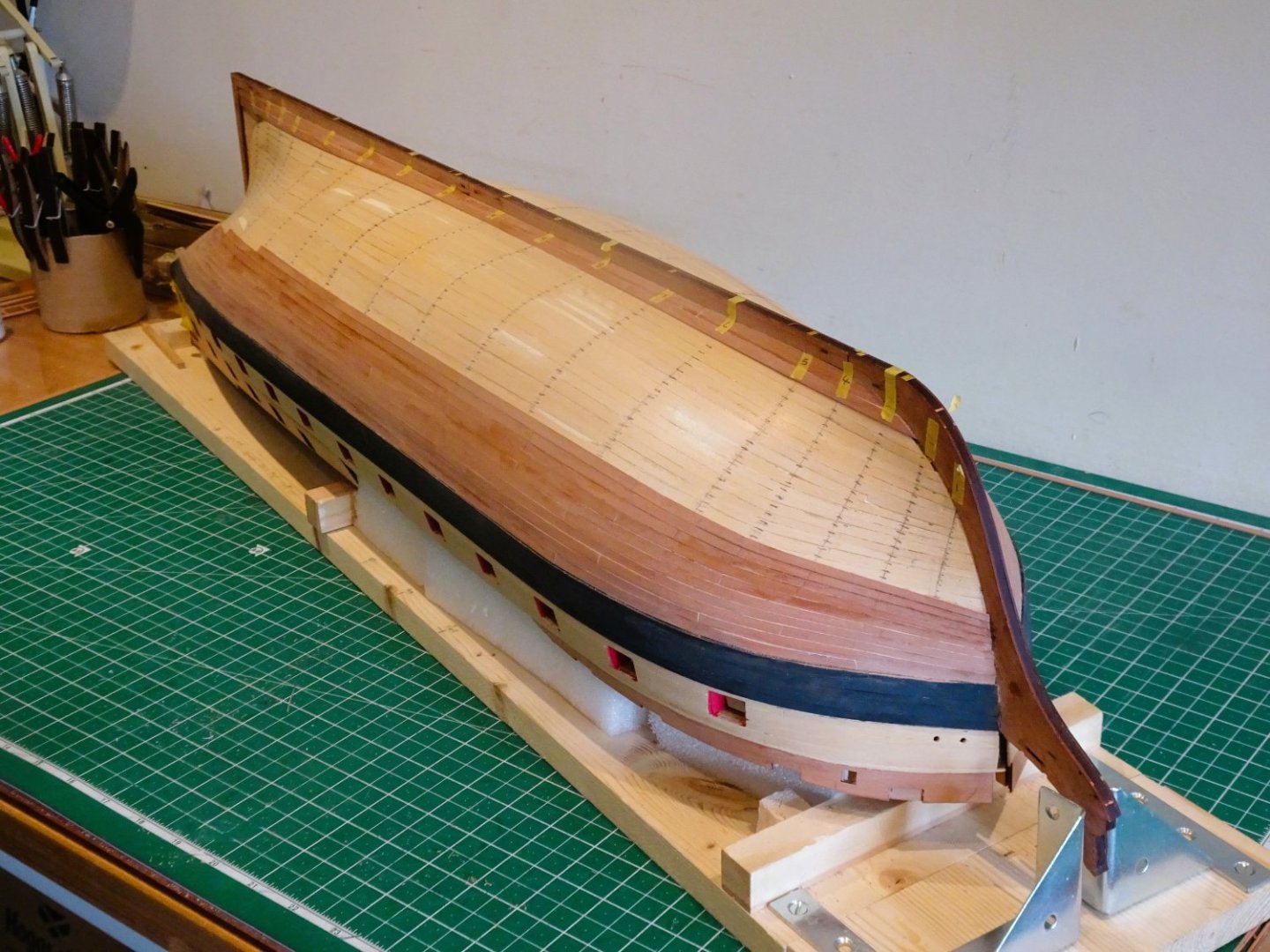
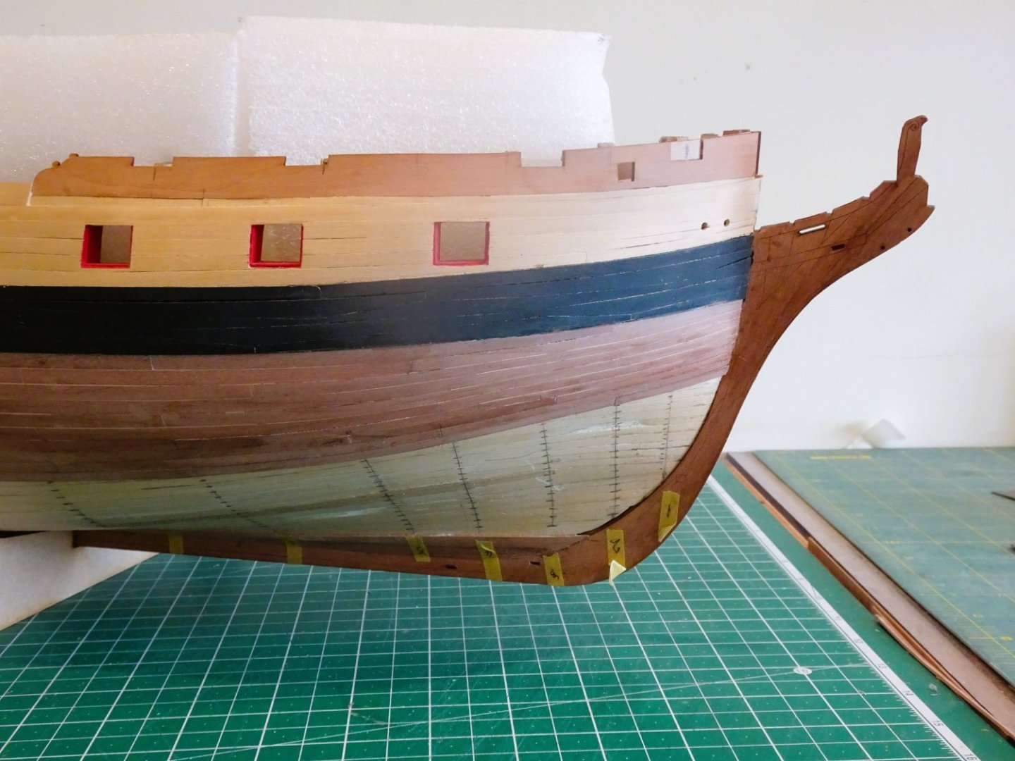
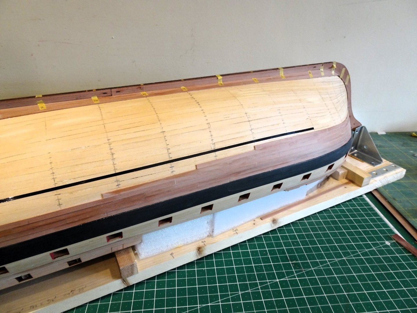
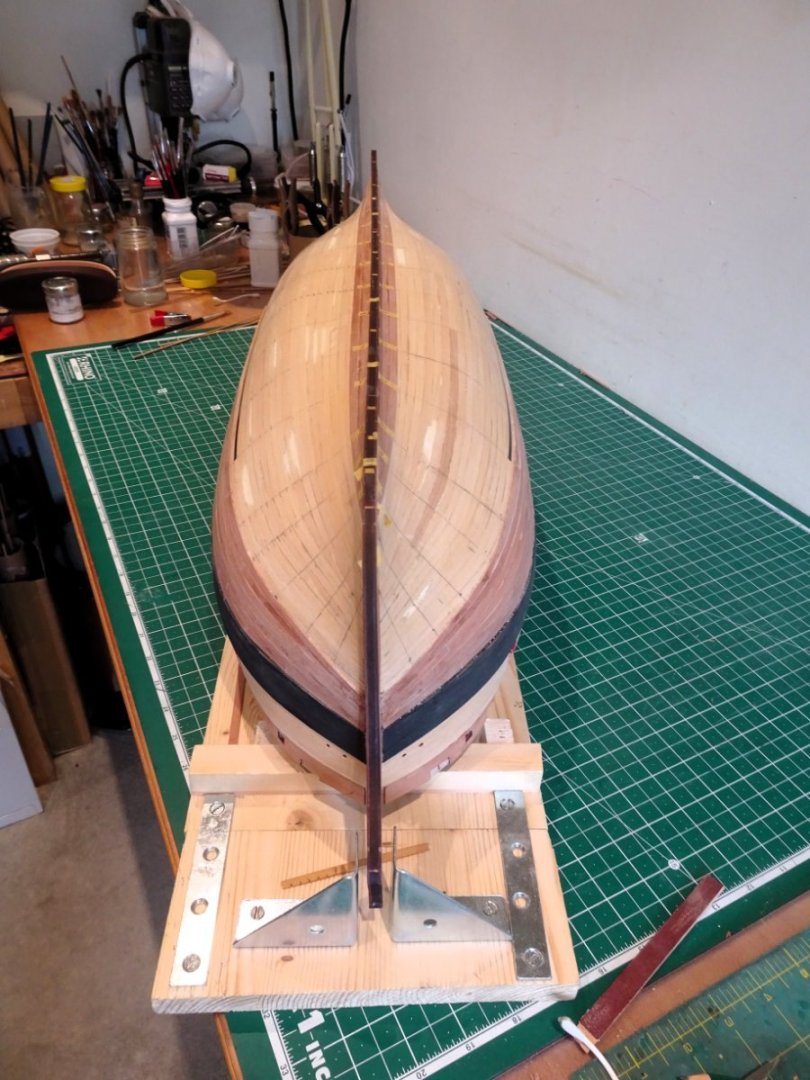
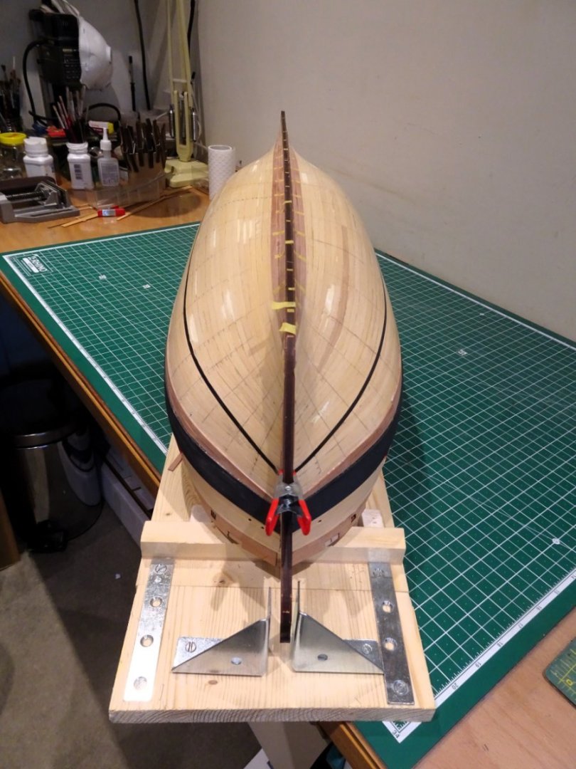
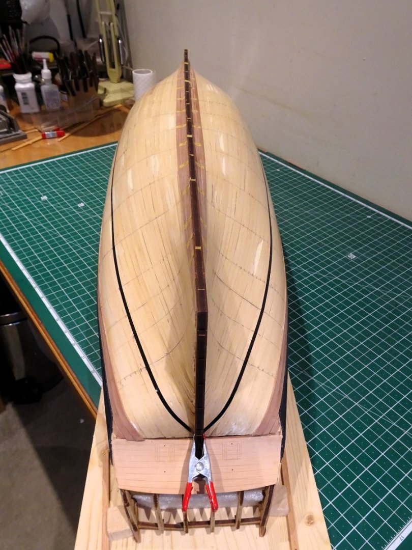
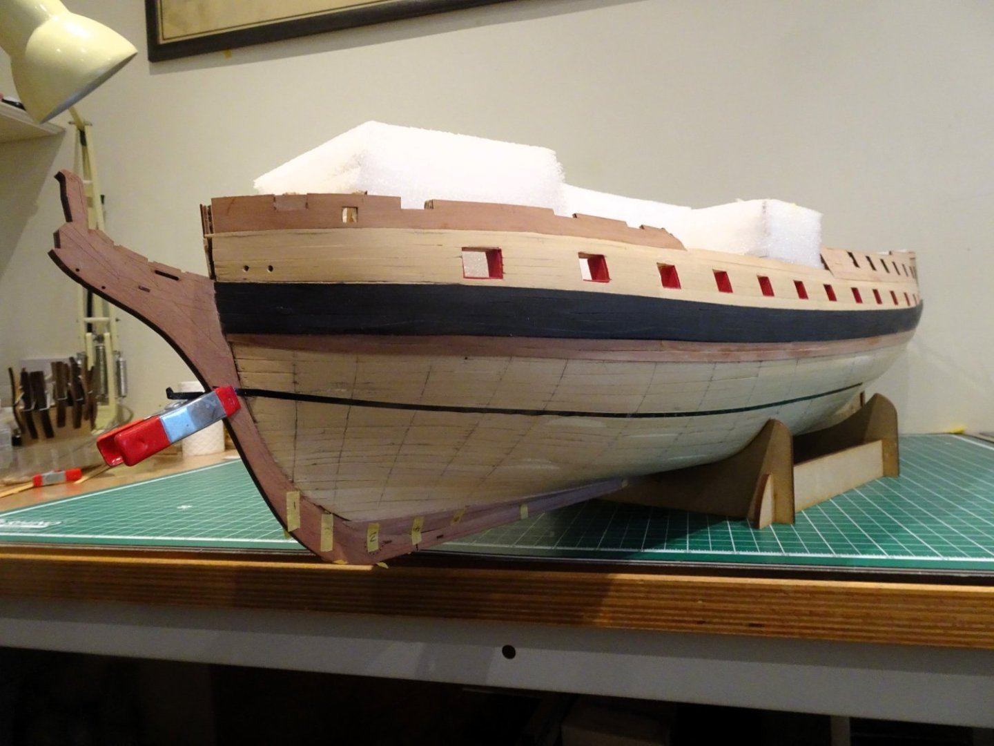
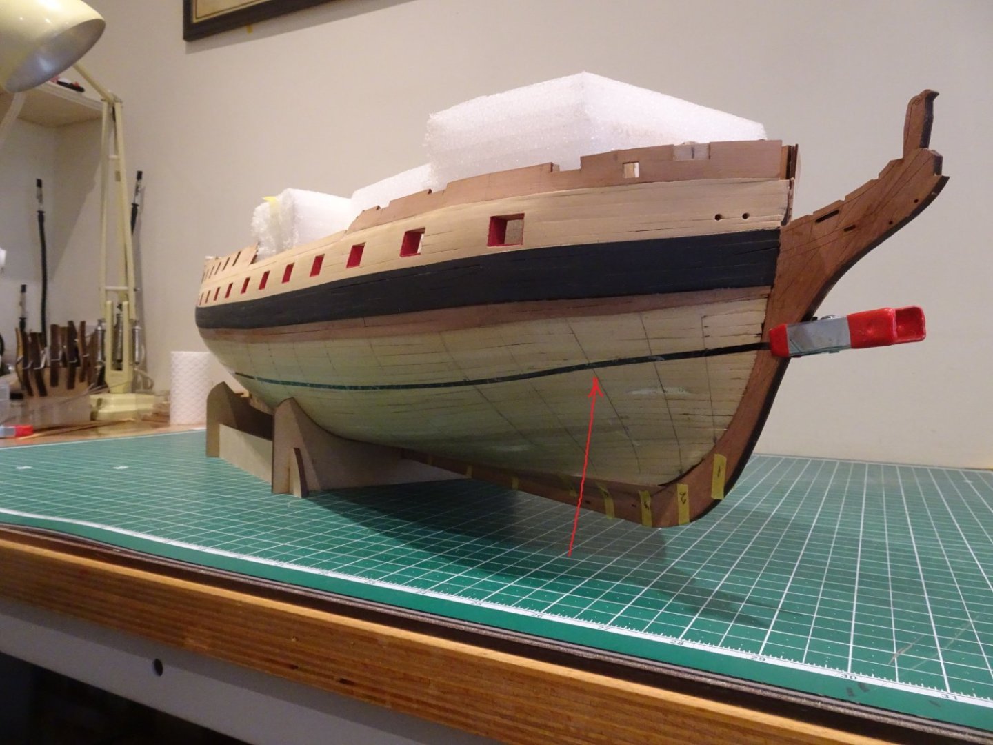
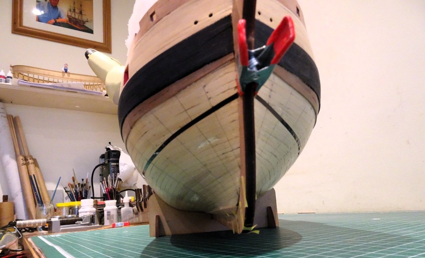
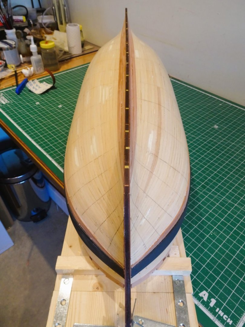
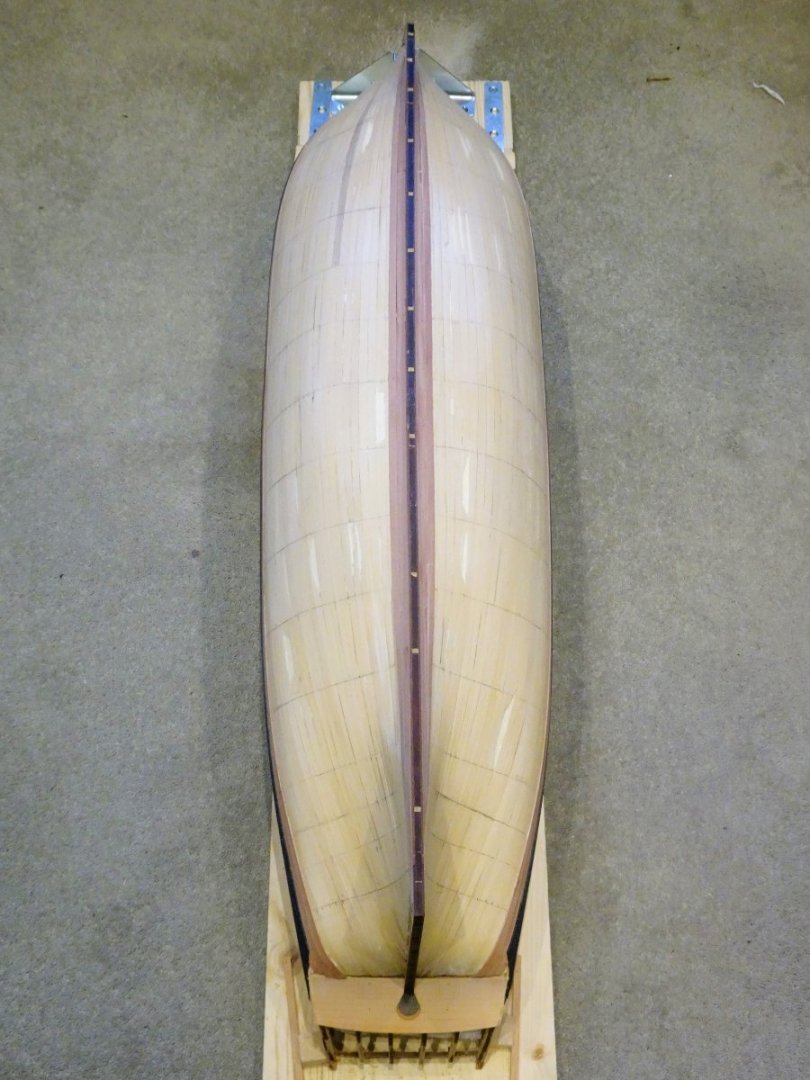
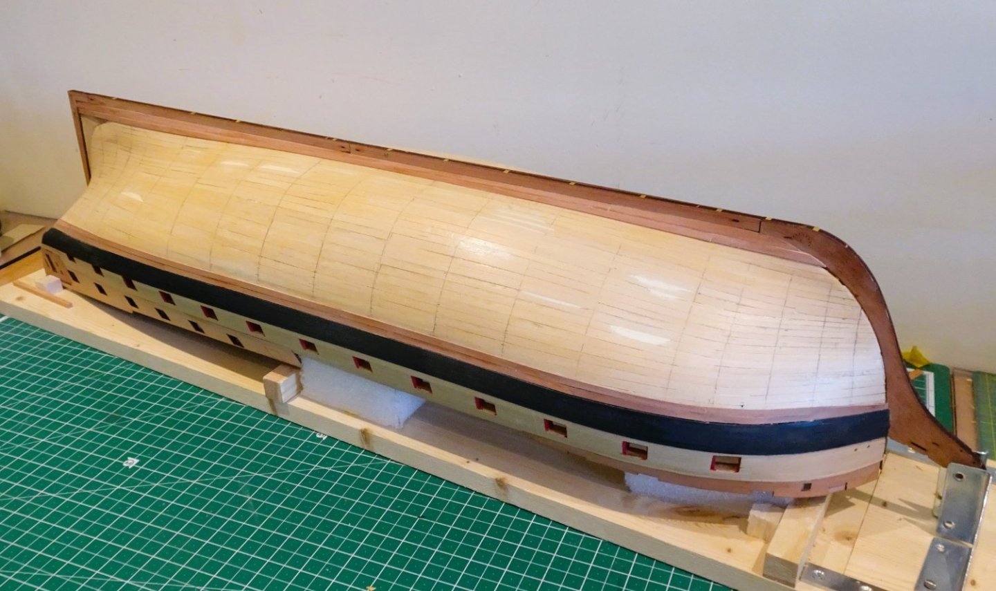
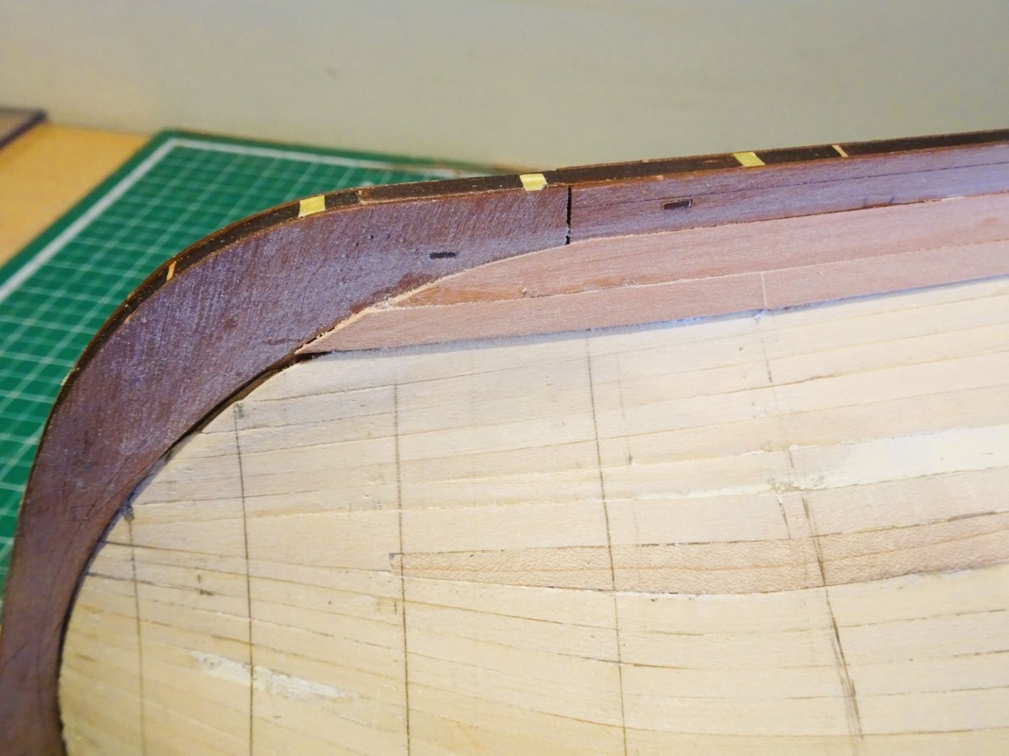
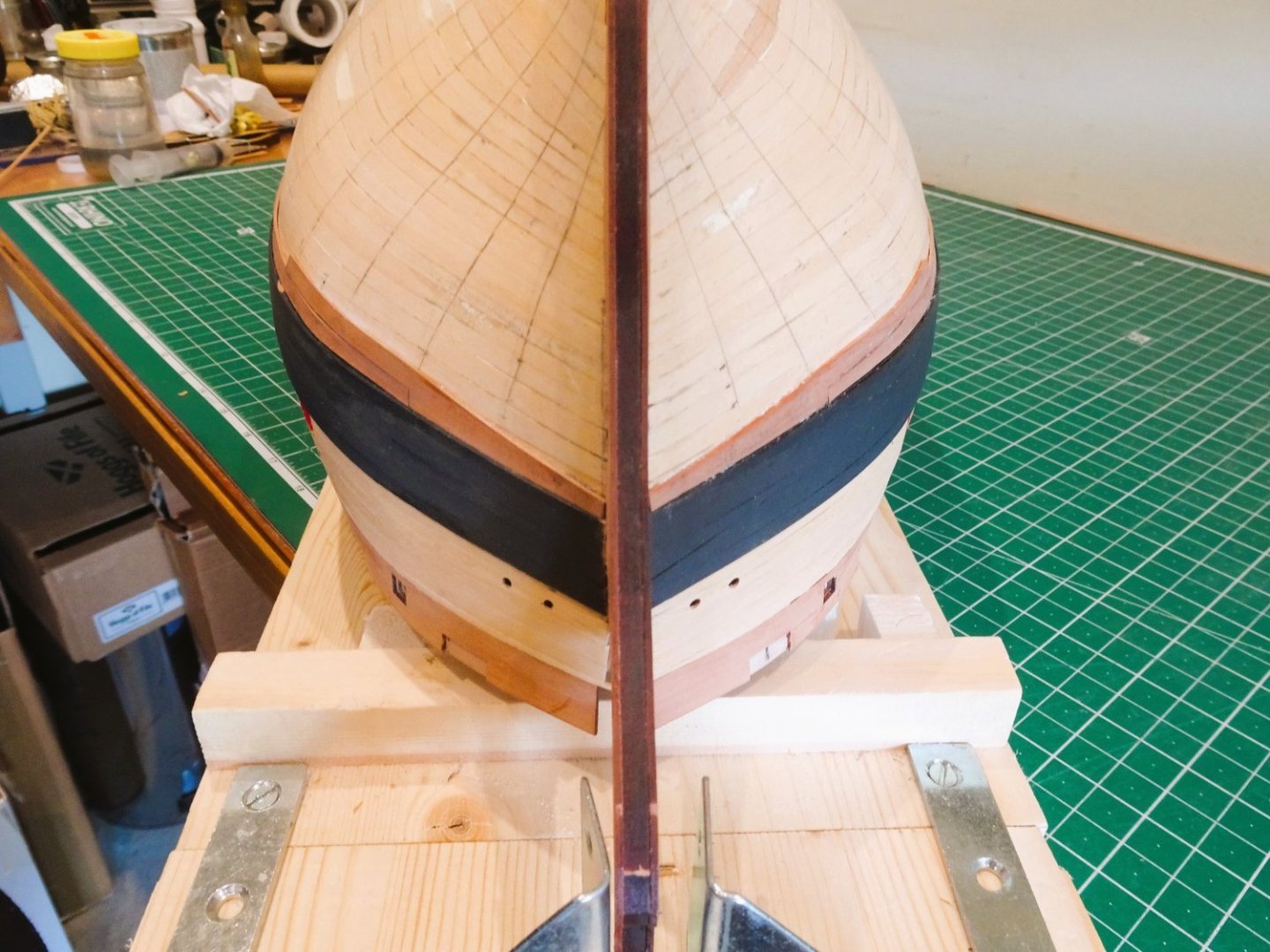
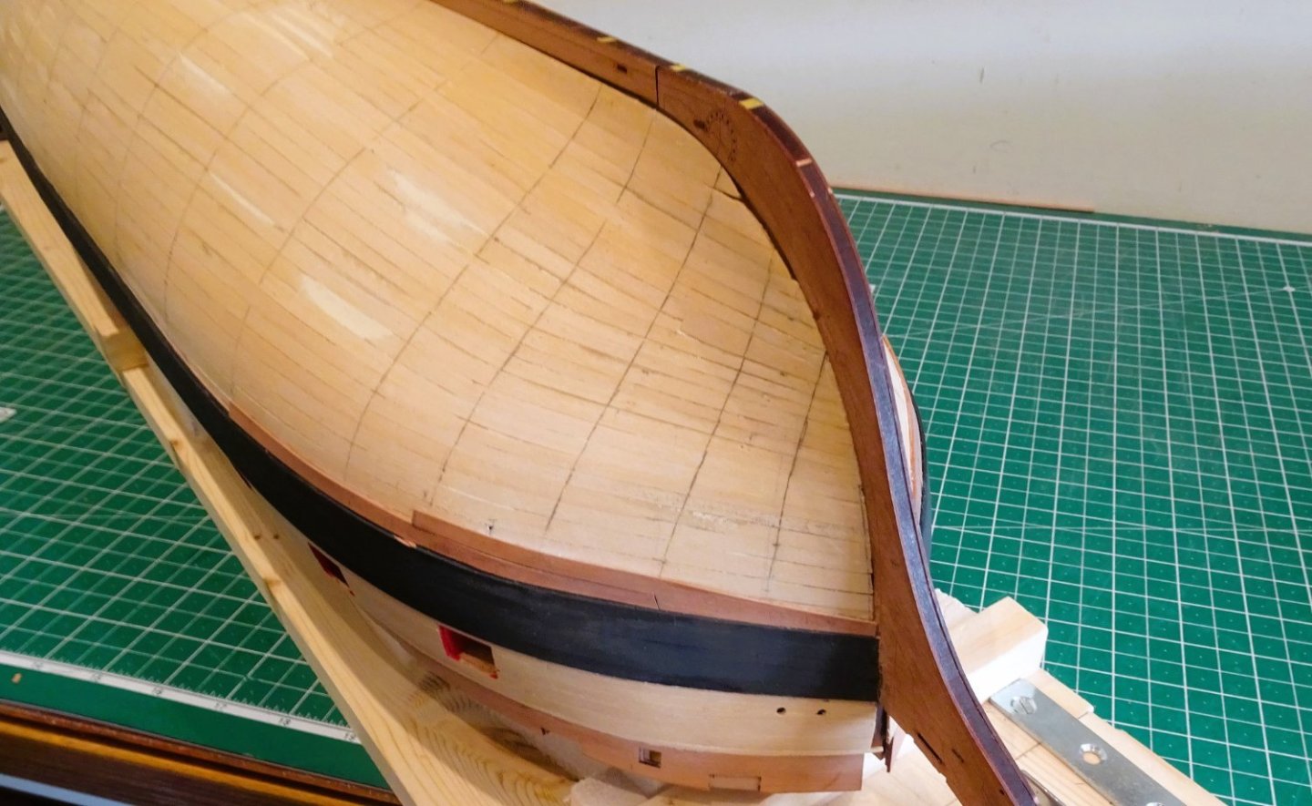
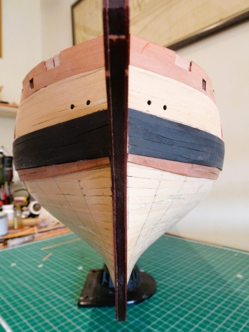
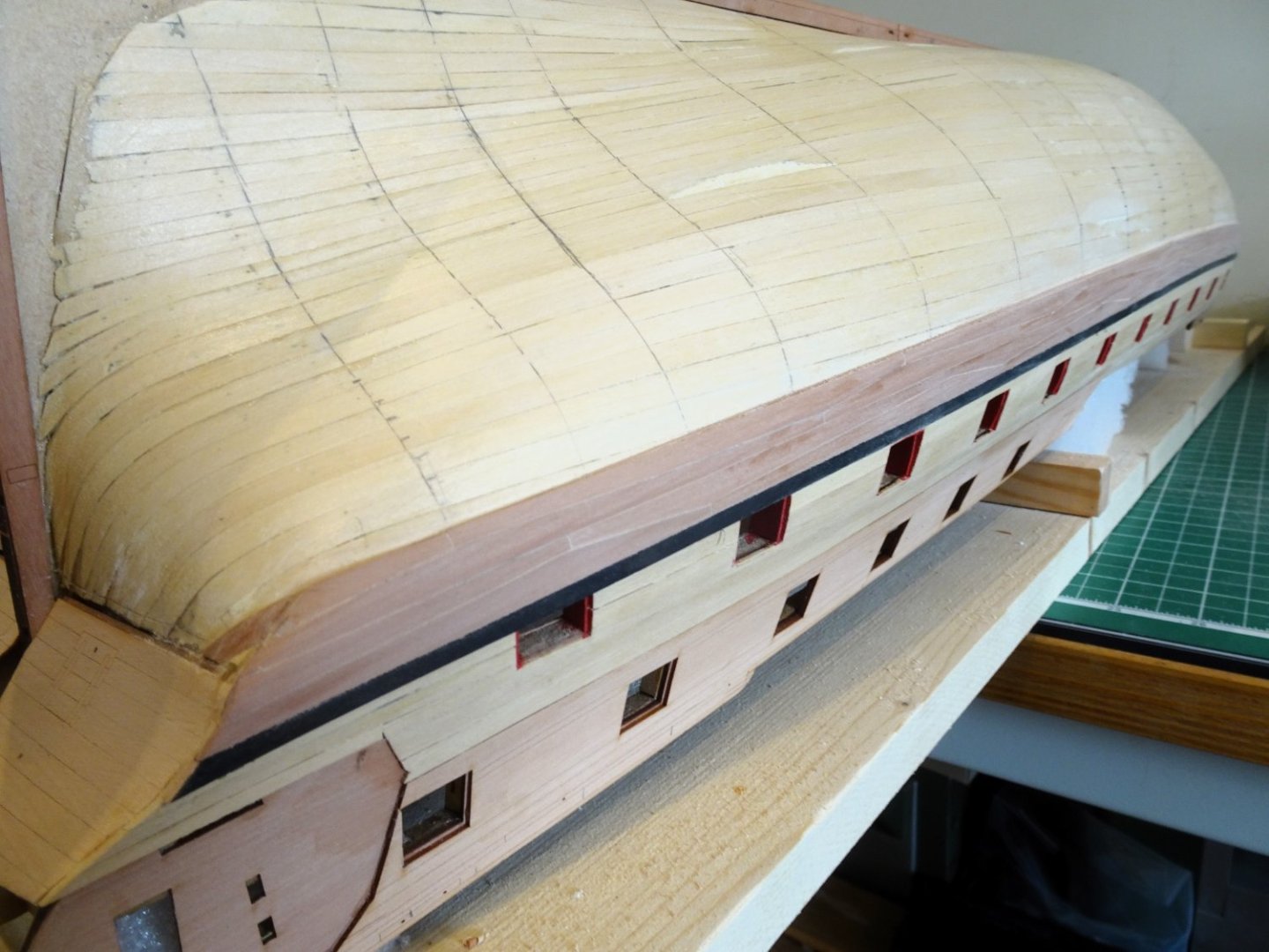
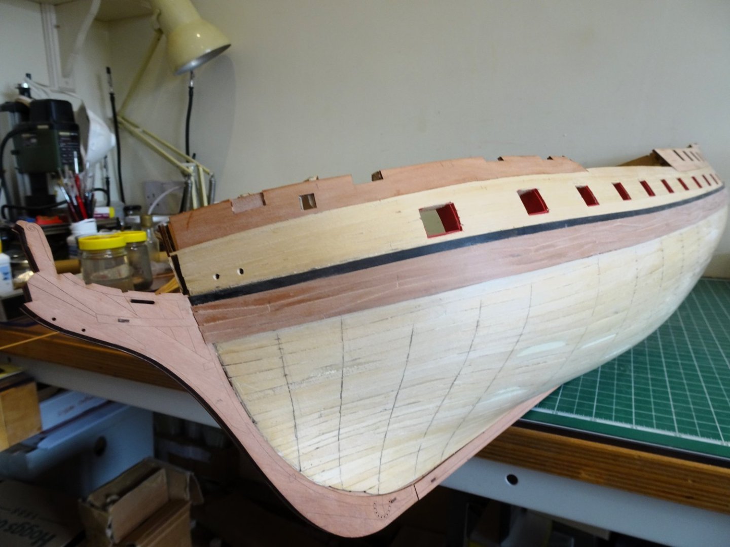
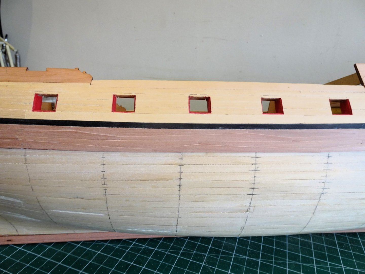
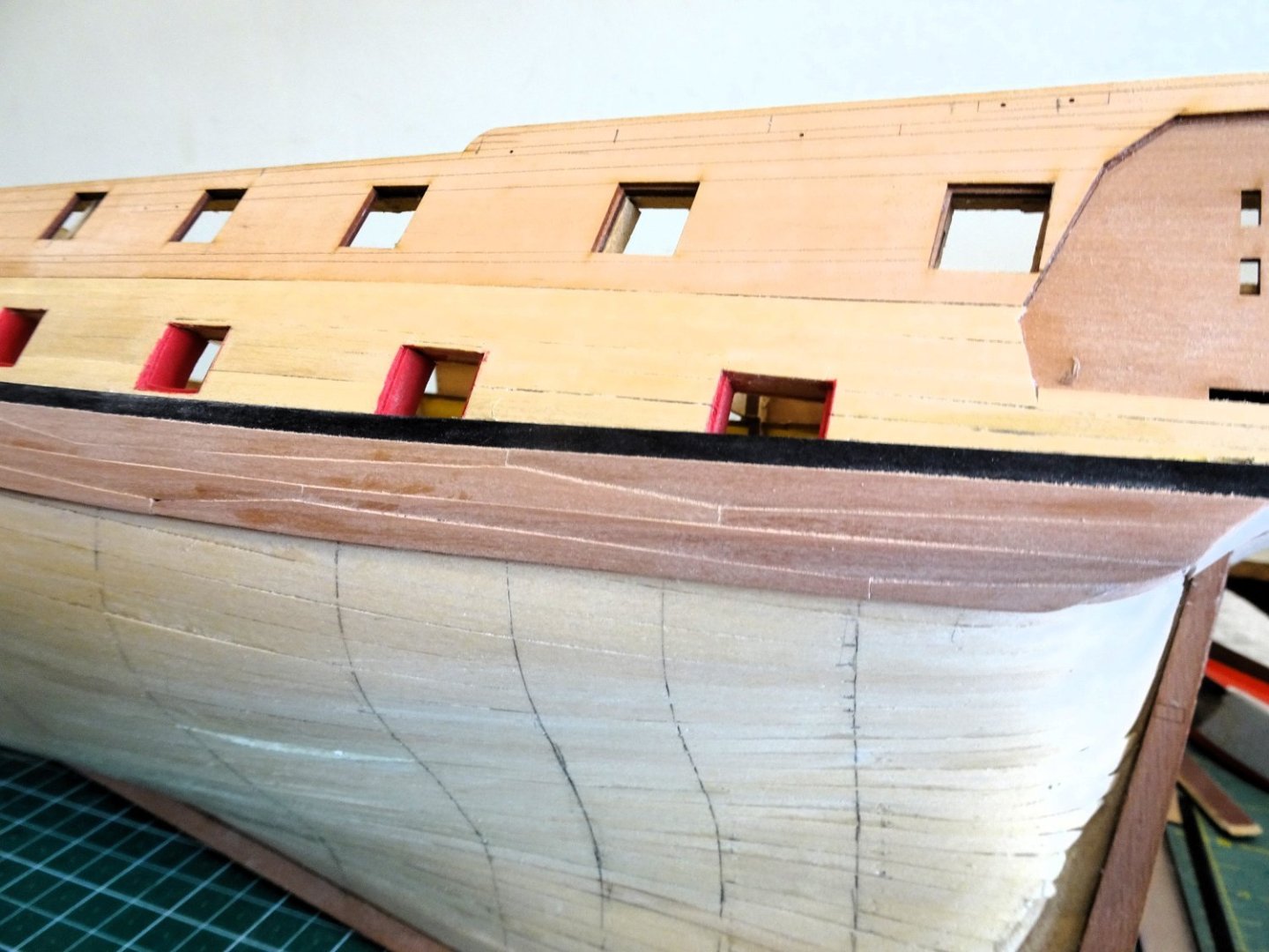
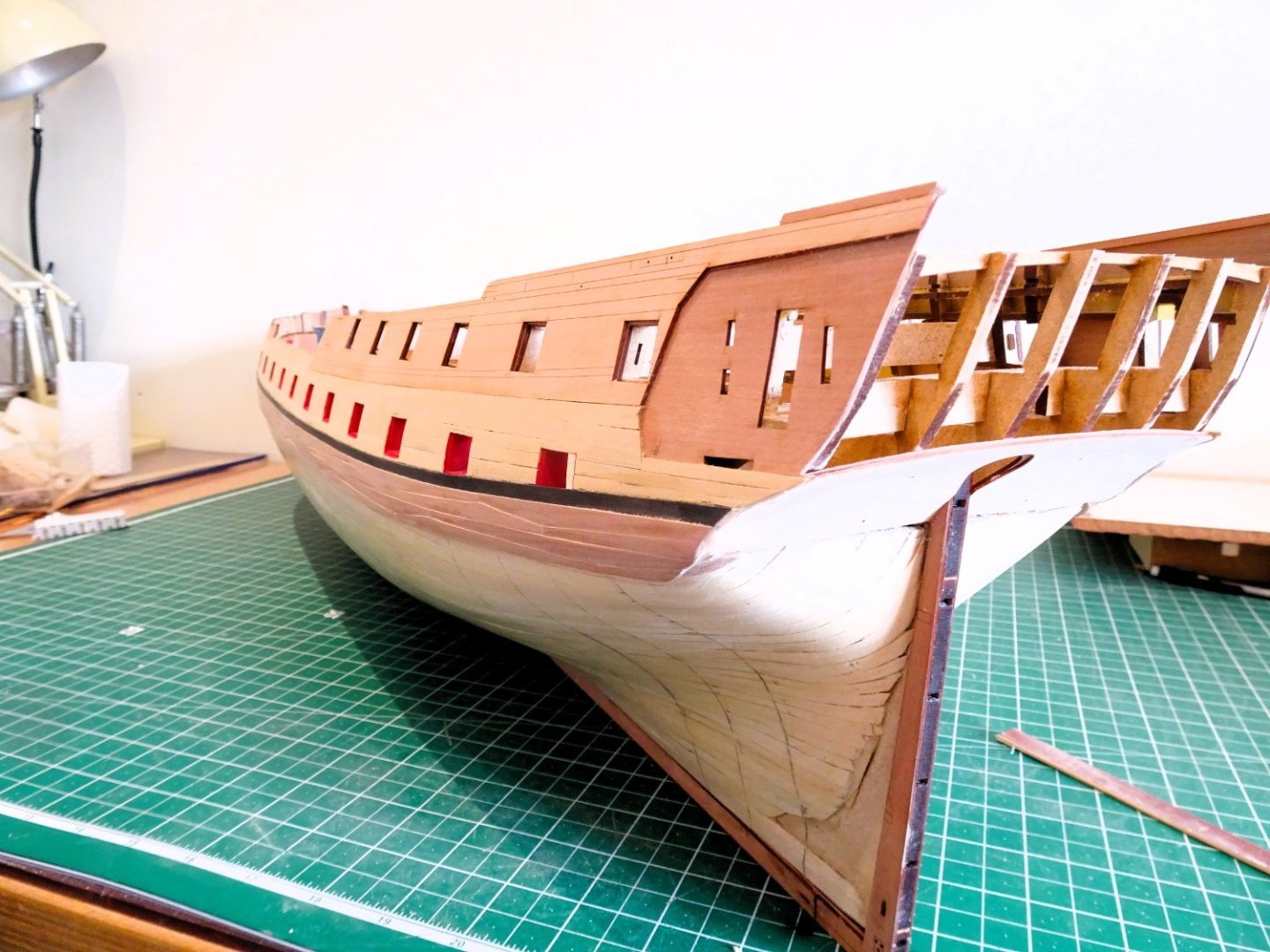
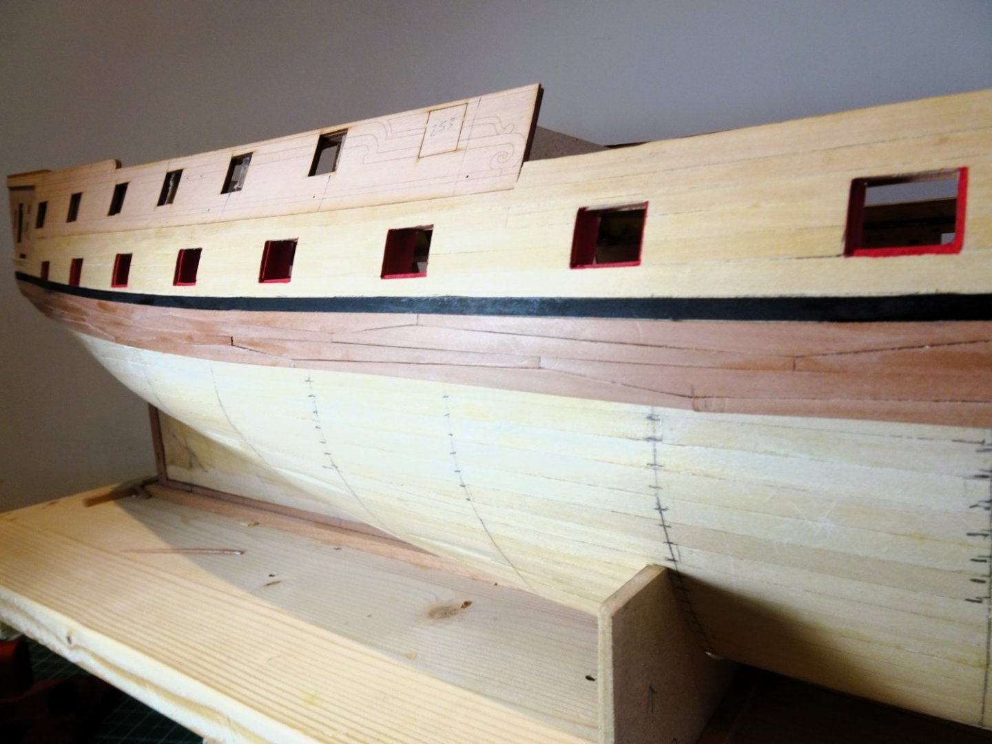
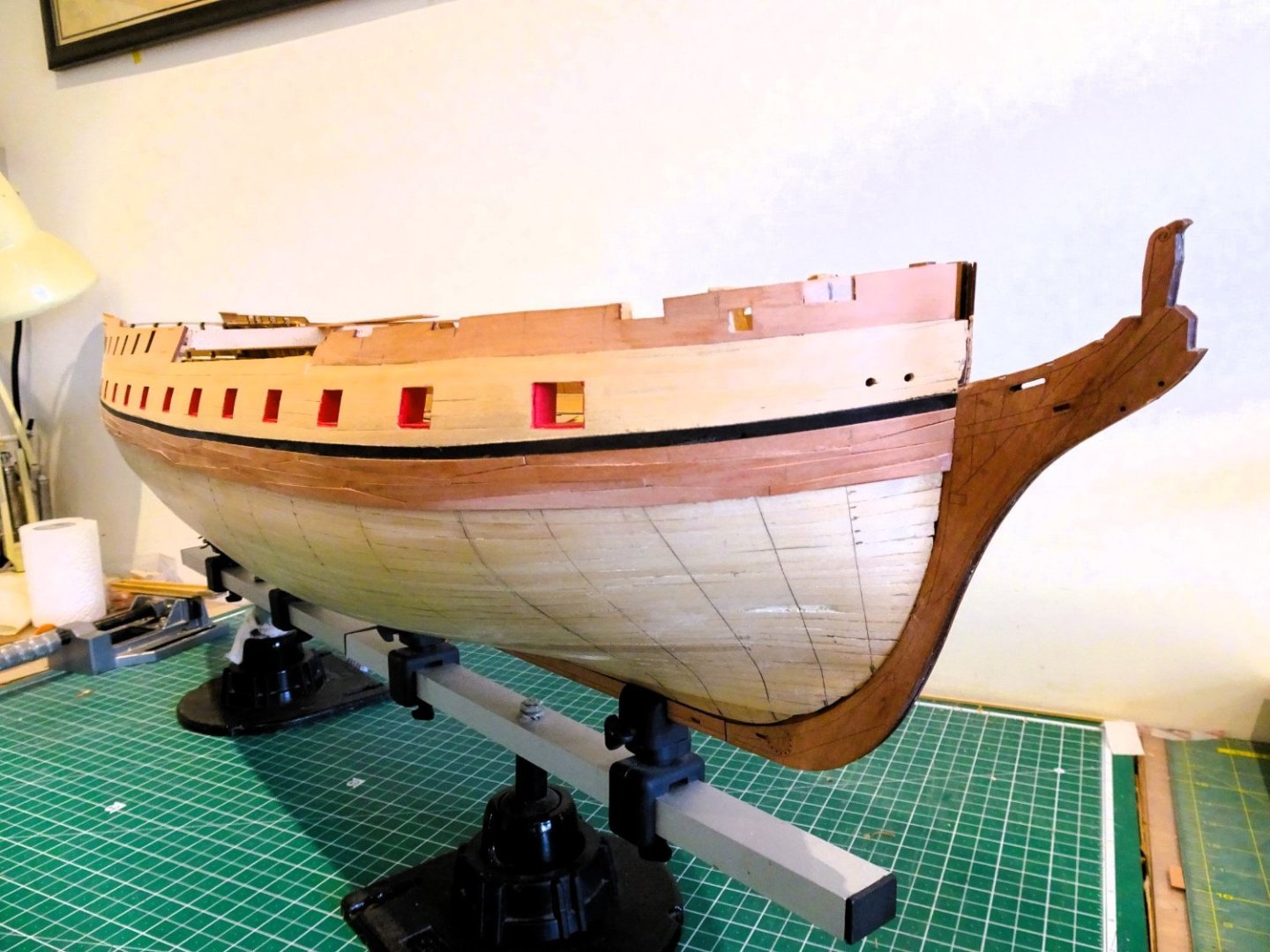
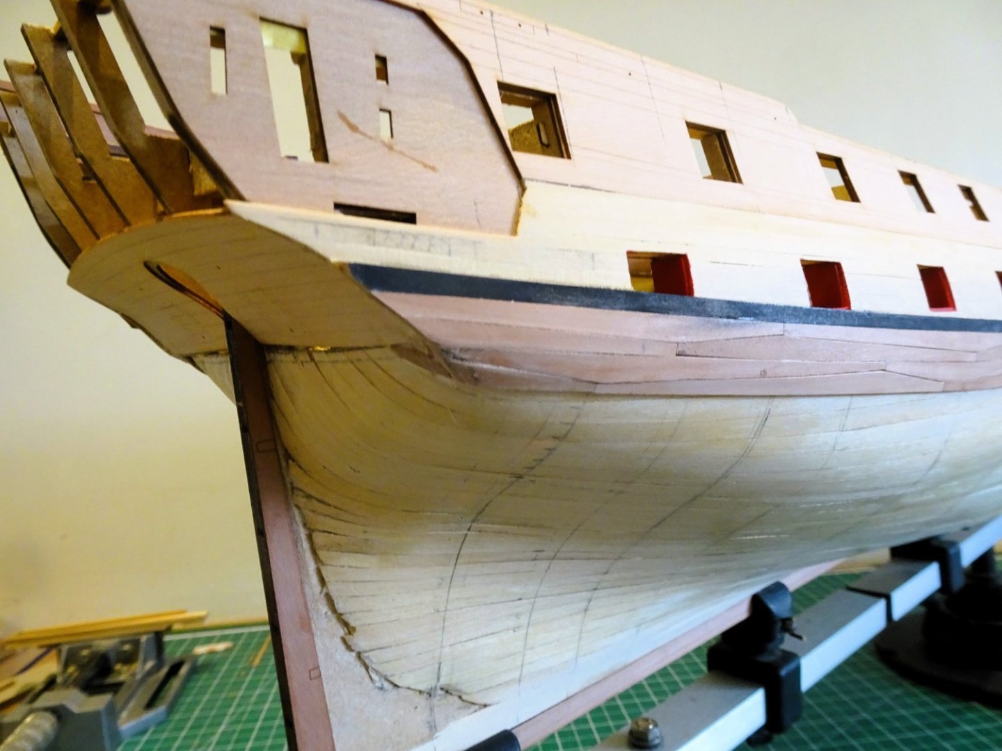
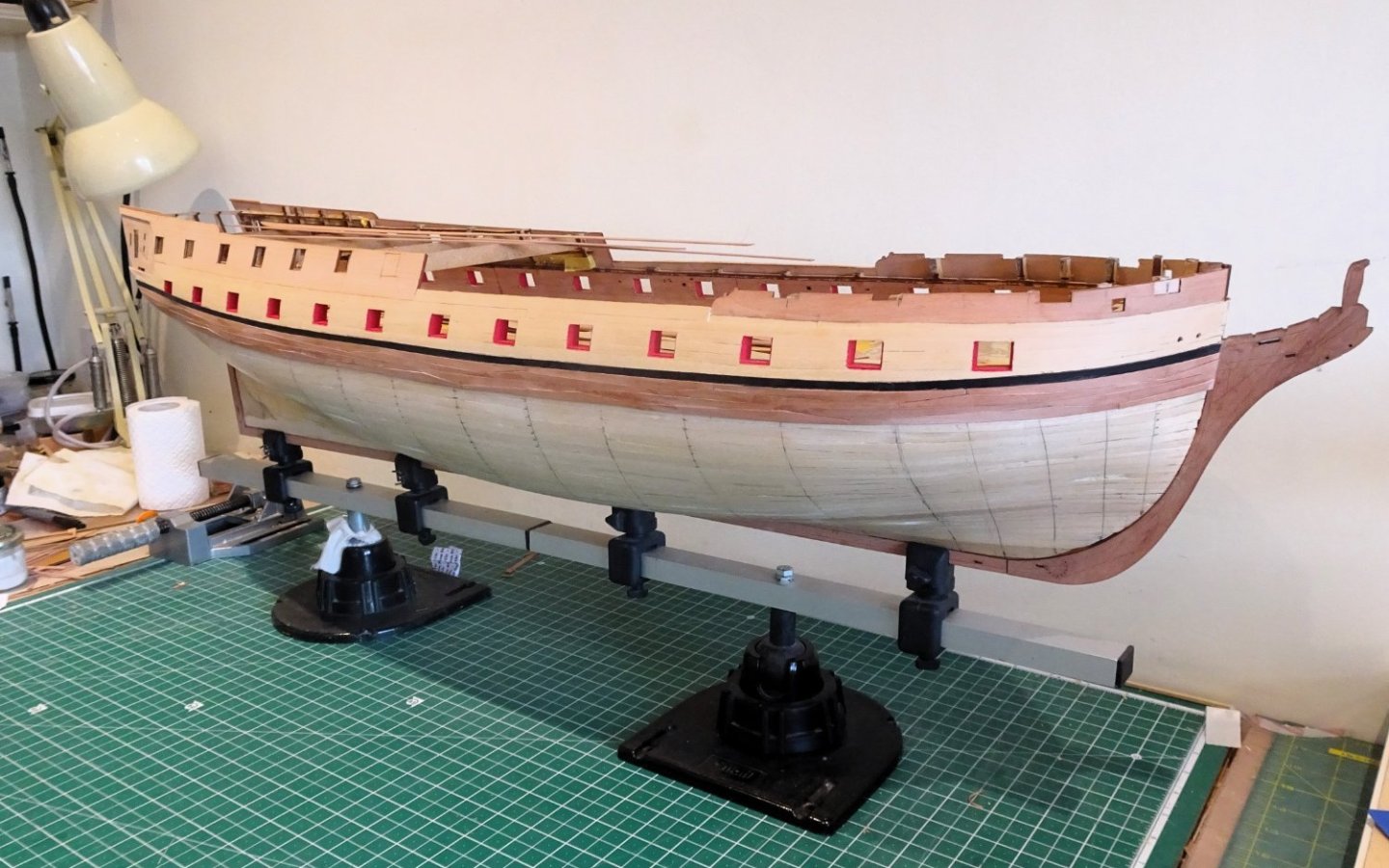
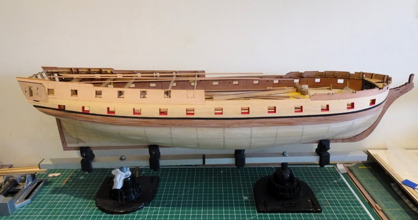
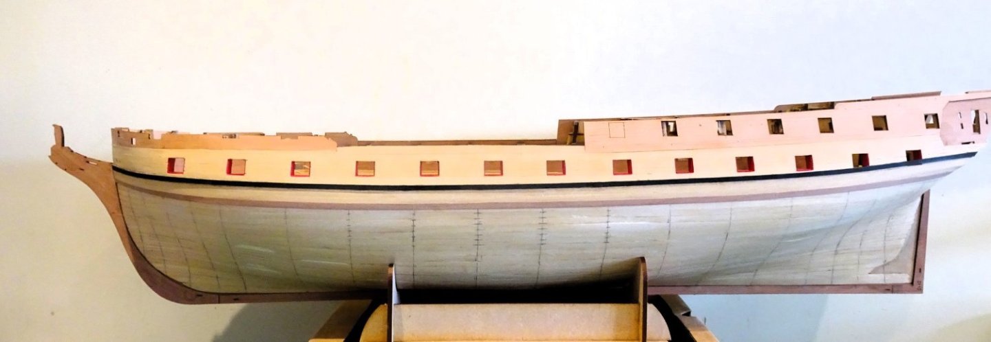
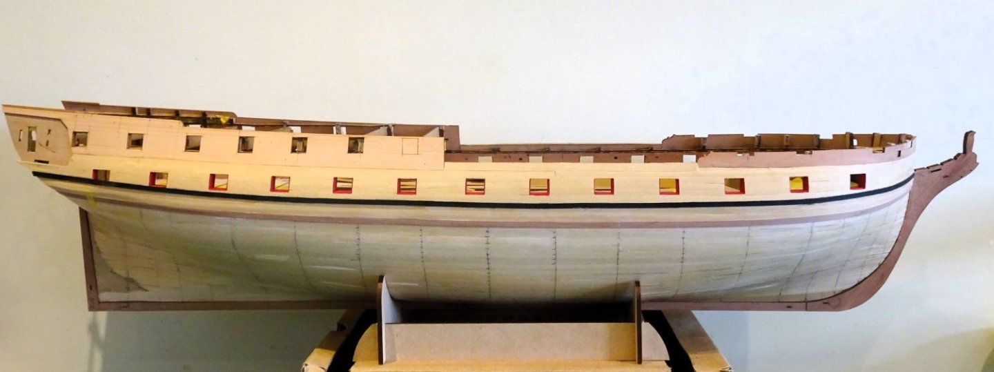
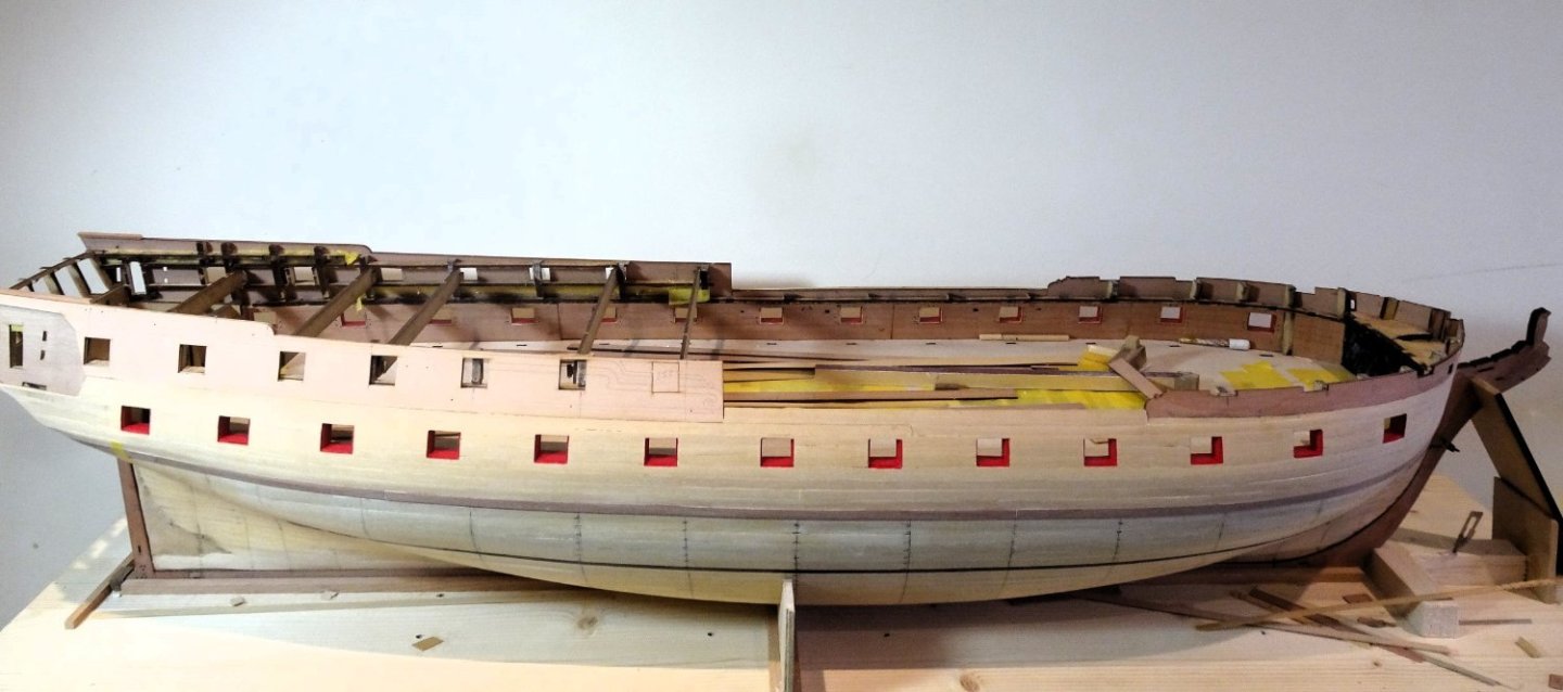
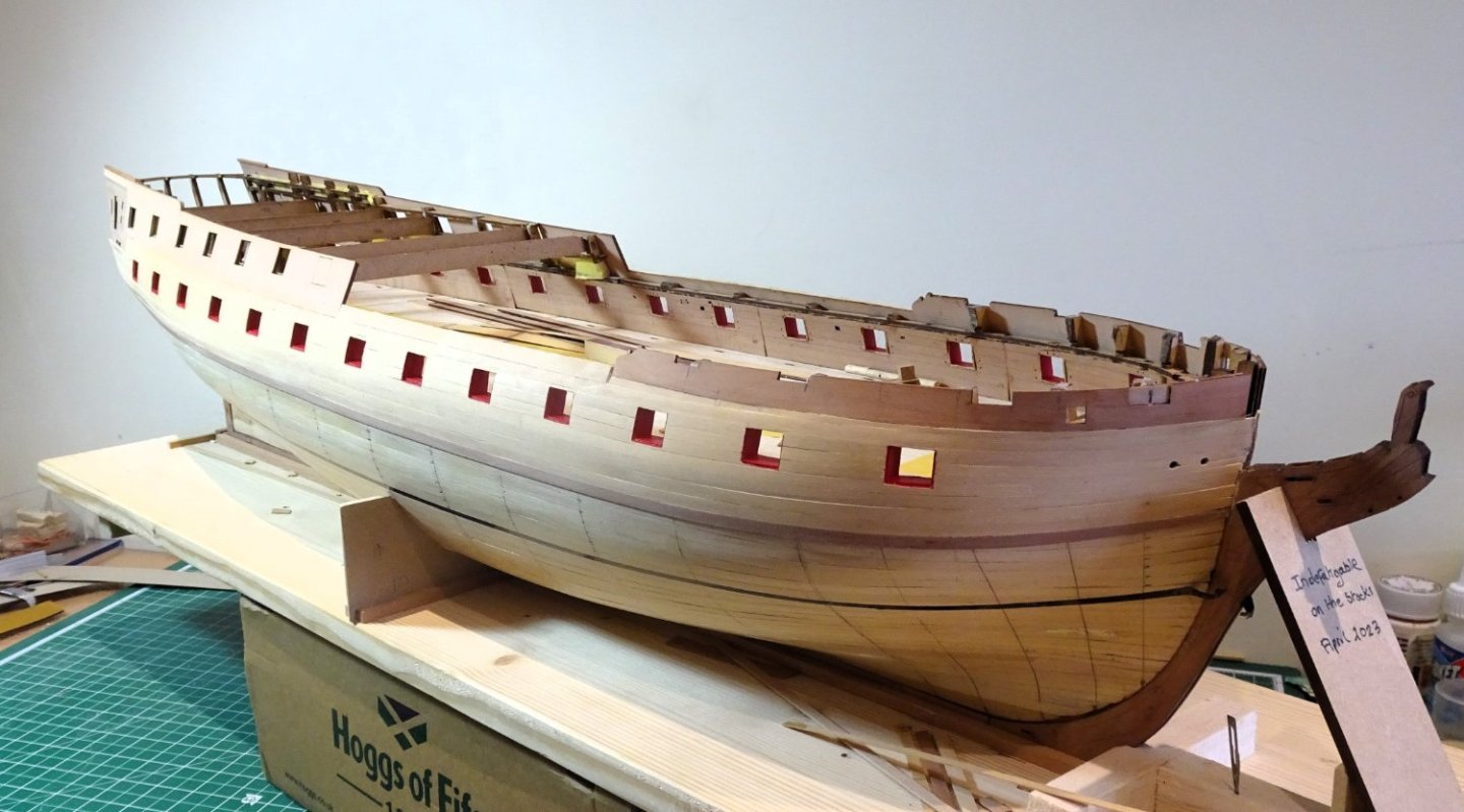
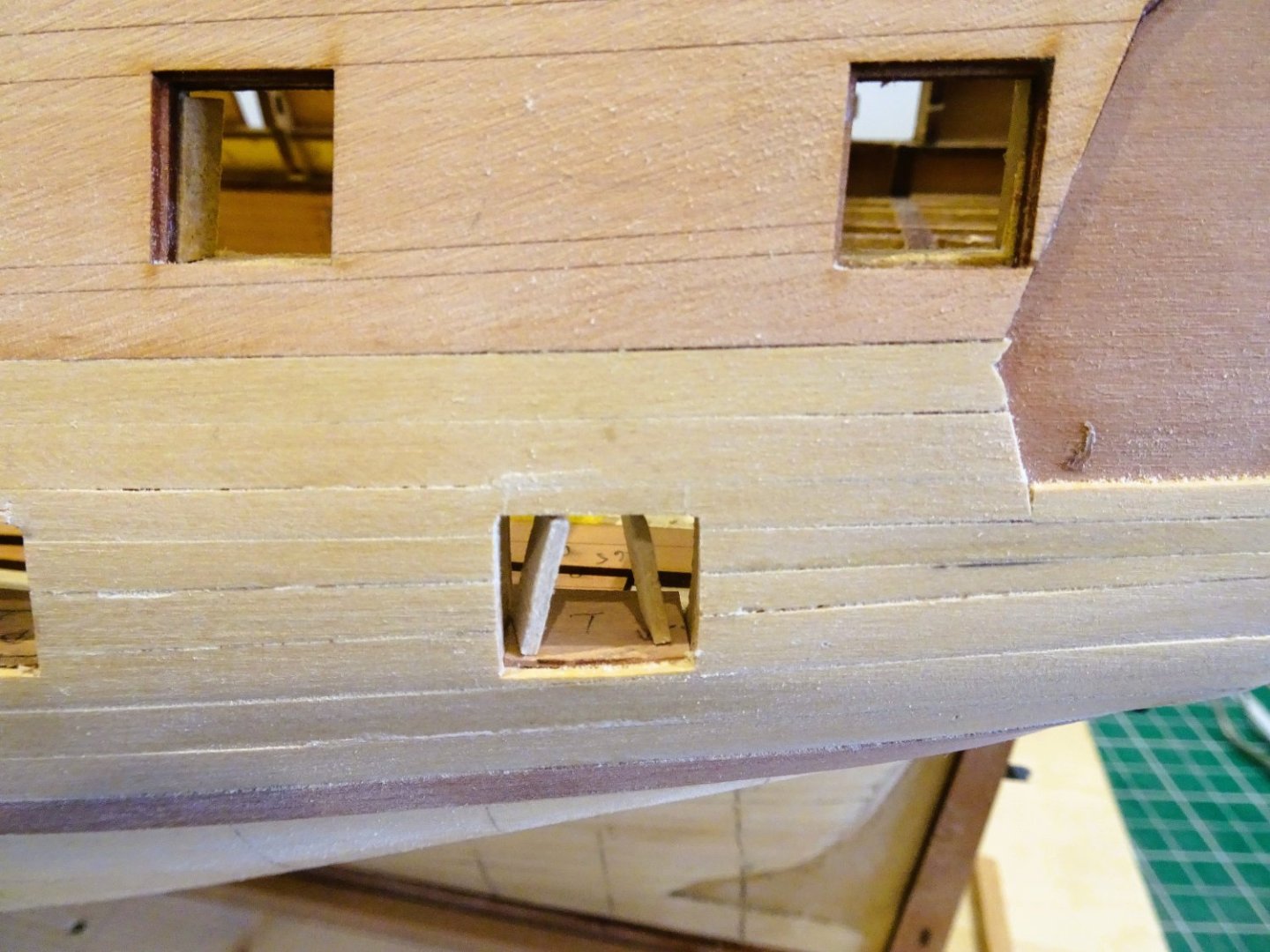
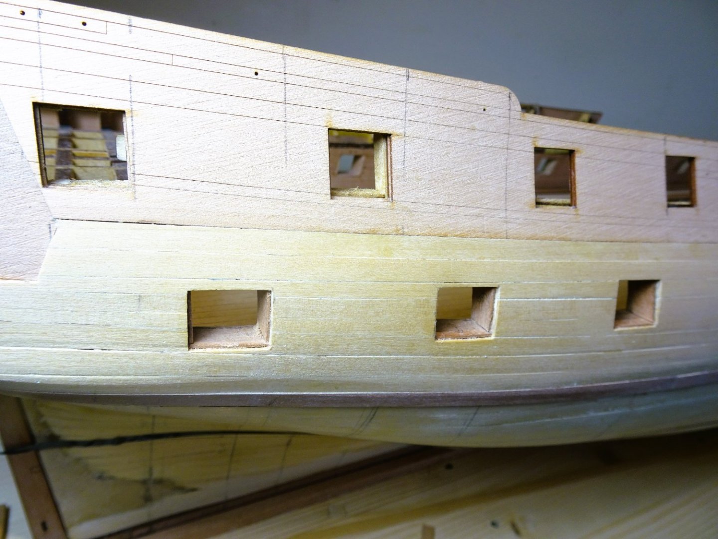
 POST Forty-five As planking continues, I become aware of an undesirable feature developing. The word is snying. In this context it relates to the excessive upward curve of a plank where the centre is higher than the extremities. 1258 This is a common problem in the bow area and I note on my hull there are slight indications of it developing eight strakes down from the wale. Probably due to deficiencies in my lining off/and or incorrect tapering, it occurs where the planks are edge bent as they round the bow, and strake upon strake, the effect is magnified. 1260 My solution is to remove a section of the last fixed bow plank, and spile in a new section to reduce the extremity of the curve for the next plank to lie against. 1261 Fortunately, the section came away cleanly without too much effort. 1262 The spiled insert is not easy to spot and is a better option than carrying on regardless with the result of visible excessive snying. 1263 With ten strakes now completed each side I am now below the waterline, and the planking runs looks better to my eye. 1268 1277 I’m about a third of the way down the hull, I will now add a further strake above the Garboard, re-check the strake arrangement, and carry on......... B.E. 03.07/2023
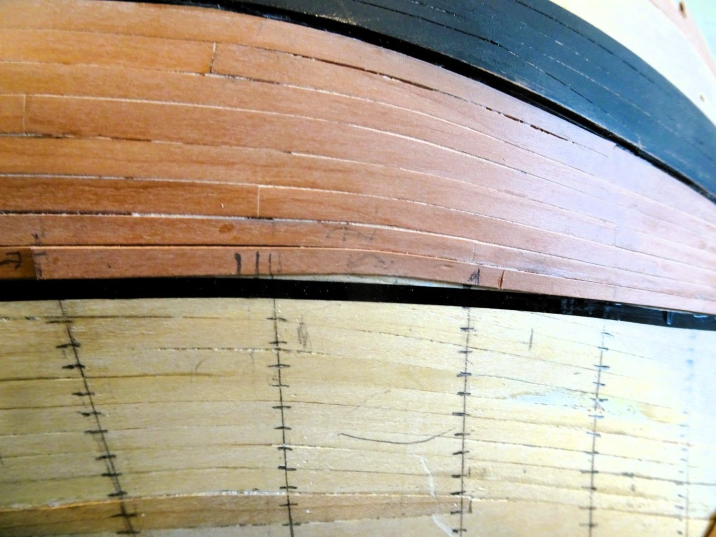

- 648 replies
-
- 28
-

-
- Indefatigable
- Vanguard Models
- (and 1 more)
-
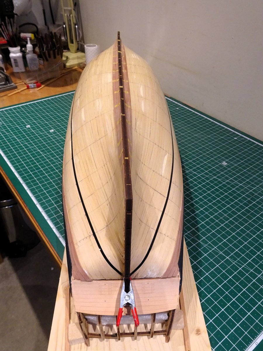
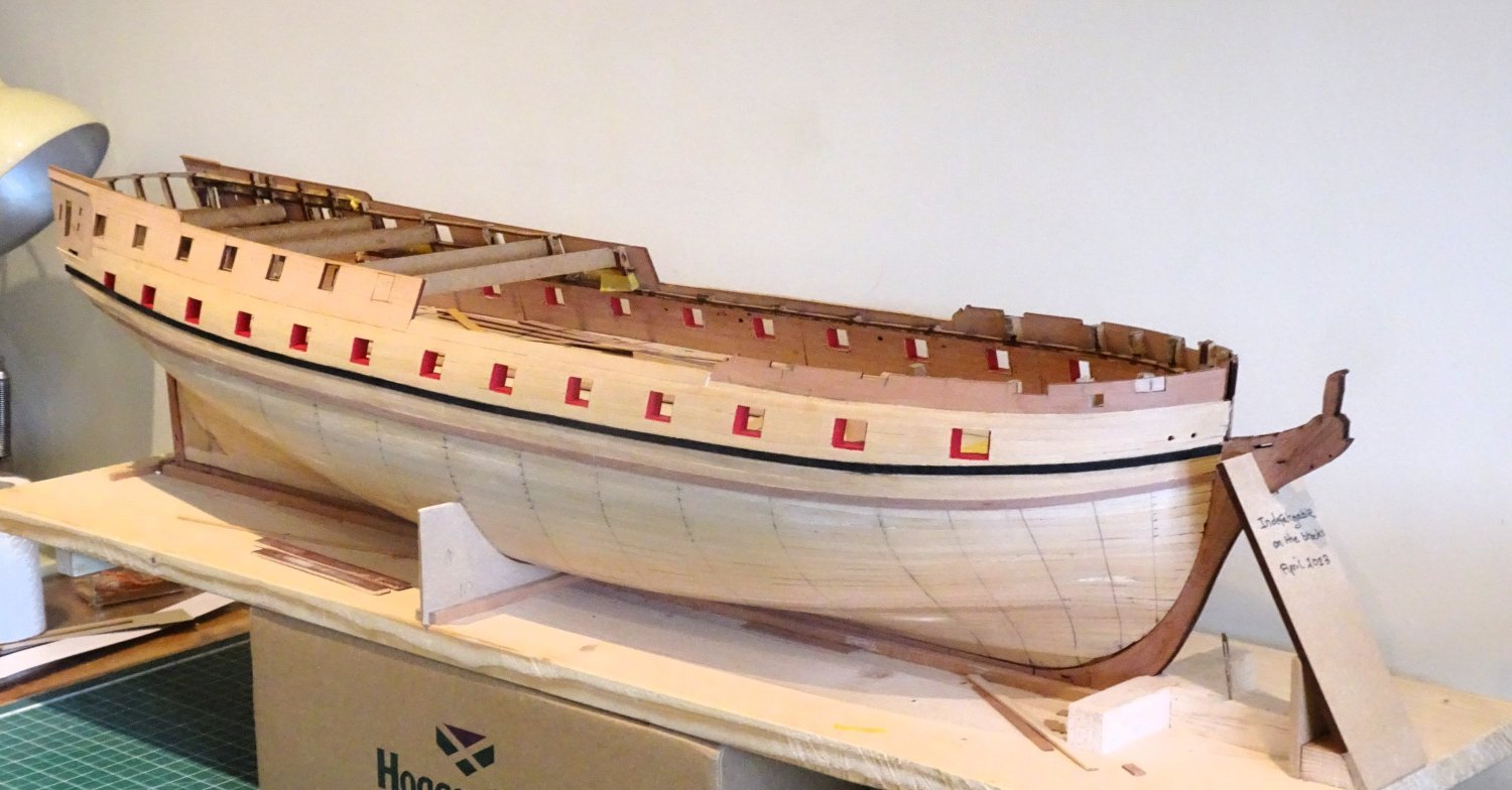
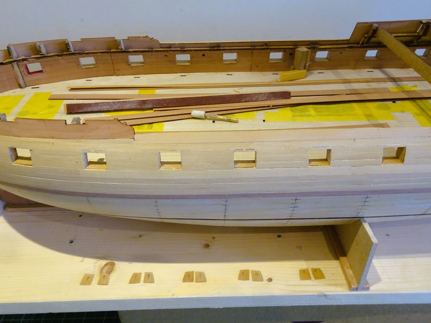
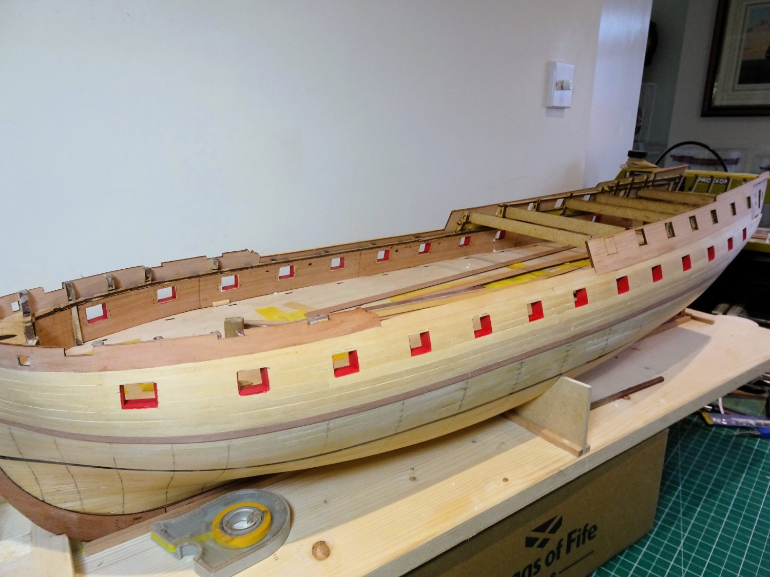
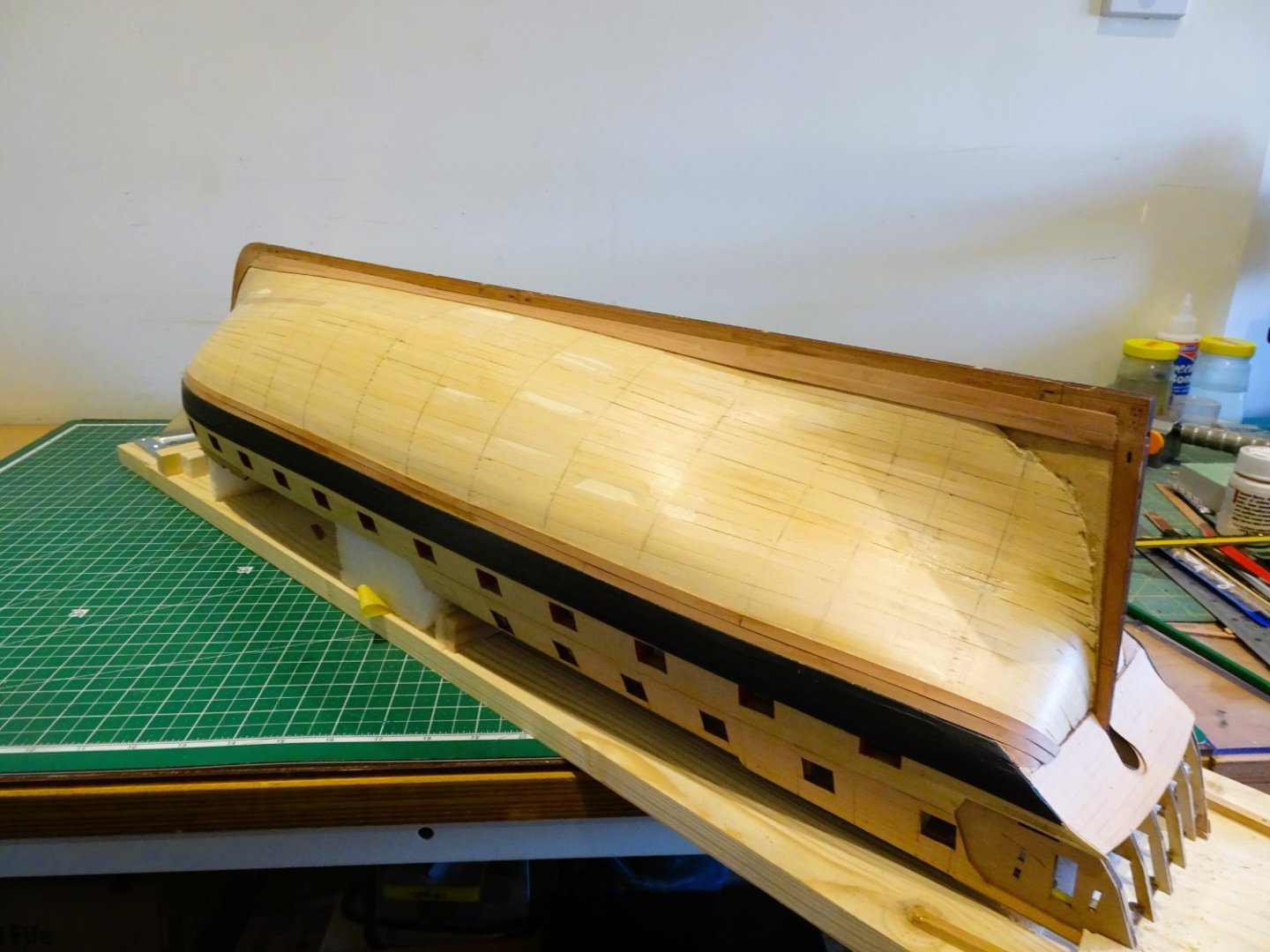
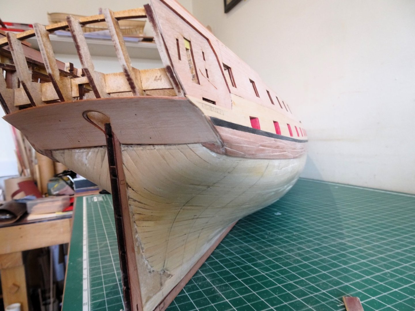
Post Forty-four The first Band. I am using fairly scale lengths with a 140mm maximum and around 45mm minimum lengths. 1219 I am not going for a set sequence of repeat patterns, but I am giving mind to the positions of butts on adjacent strakes. For deck planking I will take a more structured approach. 1224 I plank side and side about, and Ca is used throughout, with a pot of Acetone handy for wiping excess from plank faces as I go along. 1251 The required shape for the bow timbers is transferred to the planks, which are dampened, tapered, edge bent, bevelled, and generally fettled to fit. I found this necessary from around Bulkhead five to the stem. 1231 1253 One of the advantages of the Indy hull is that apart from the bow area there are long sections of using full width planks which proceeds quite quickly. 1247 Looking a bit rough at this stage, but I now need to re-mark the hull for the next band of planking. Onwards…. B.E. 01/07/2023


- 648 replies
-
- 25
-
-
- Indefatigable
- Vanguard Models
- (and 1 more)
-
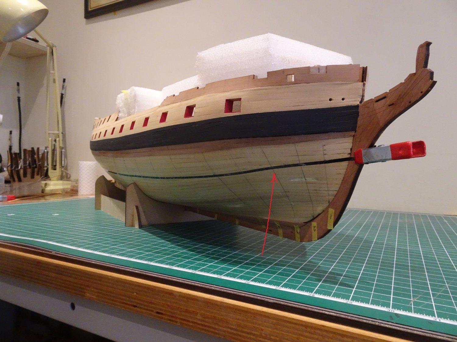
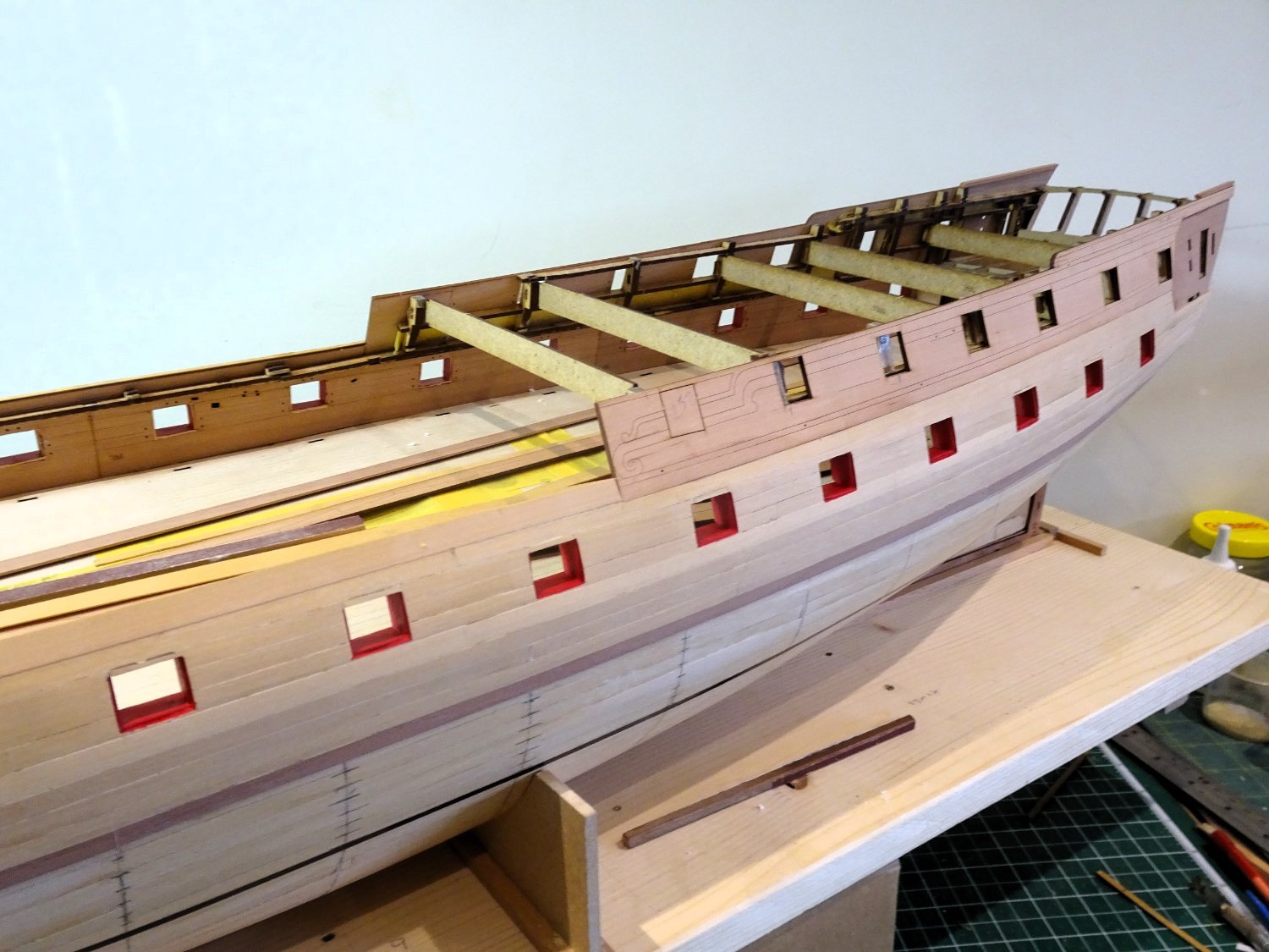
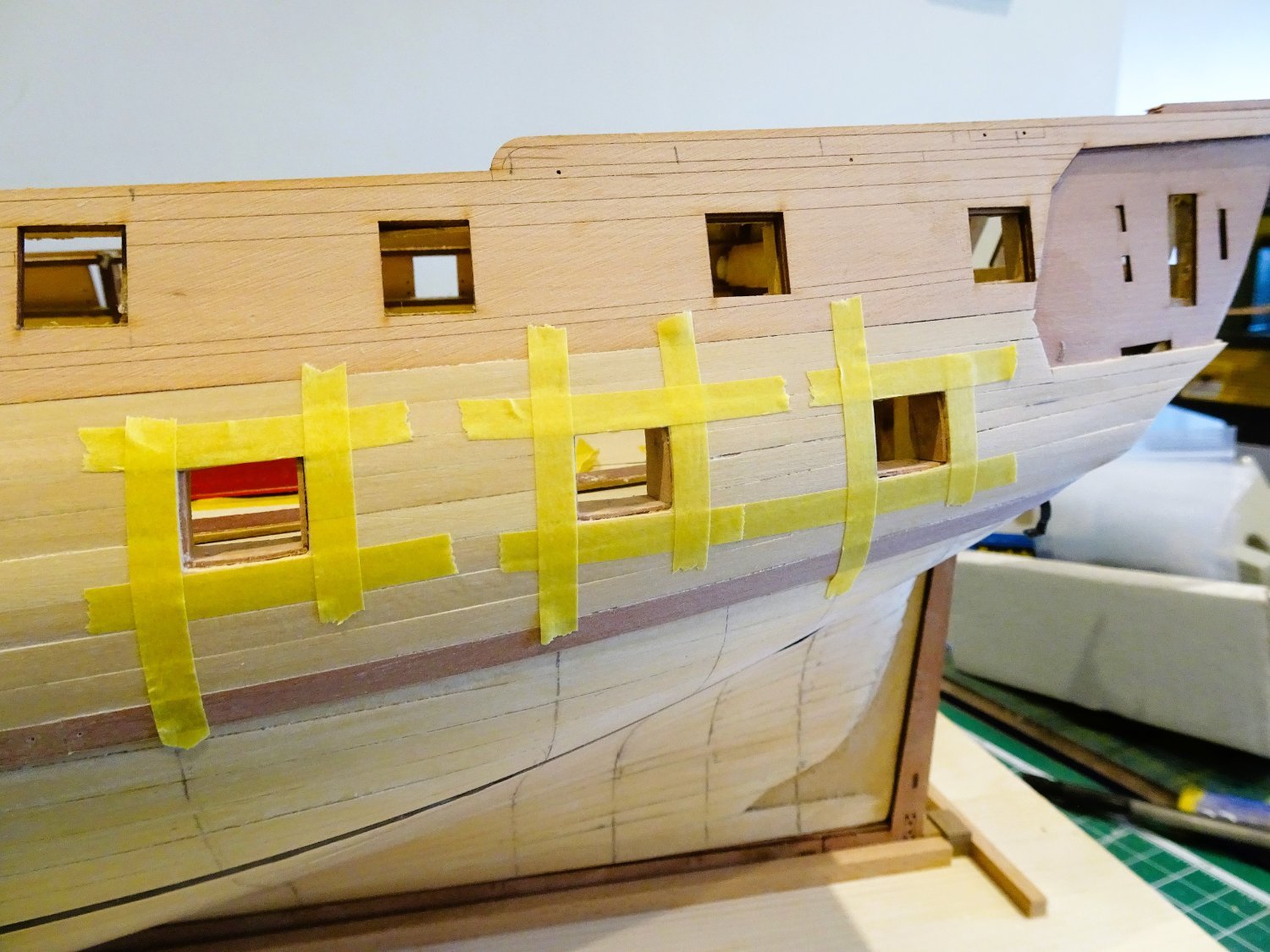
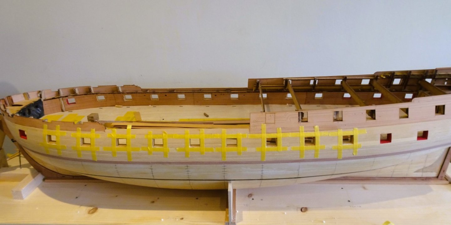
Post Forty-three The Preparation I have (26) 5mm planks at midships which are marked off on the hull using a tick strip. I intend to work a first band of six strakes below the existing planking, and I’m looking to have the plank ends at the stem not less than 3mm in width. With this in mind, I apply the lining tape. 1173 1179 The first application of the tape, now the tweaking begins. In these shots the upper tape marks the line of the first section. I am aiming to get a smooth sweep up to the stem using edge bent and tapered strips only. I hope to avoid the need for spiling except perhaps when I reach the under belly of the hull. The trouble with lining off is deciding when it is at its optimum line. This process is more art than arithmetic and I find myself in an agony of indecision wondering whether I have reached that point. Using strip wood there is inevitably error creep strake upon strake, so I will fit the first section and then recalculate. The following photos show the point where I think I am getting close to an acceptable run. 1191 1193 1195 1199 1212 1205 1207 1203a I think it needs a slight tweak as indicated. 1216 This looks better to my eye. I can now proceed to mark off the strake widths at each bulkhead point and begin planking. B.E. 27/06/2023.


- 648 replies
-
- 19
-
-

-
- Indefatigable
- Vanguard Models
- (and 1 more)
-
So, you could be up for another 30hrs work to complete both sides, a testing exercise Kevin, and that's without any consideration of copper nail heads.🫤 She will look good tho' with the copper against the black.👍 B.E.
- 443 replies
-
- 5
-
-
- Indefatigable
- Vanguard Models
- (and 1 more)
-
Looks to be going on ok Kevin,👍 Are you cutting individual plates, or applying longer strips, and marking the vertical plate joins post fitting? B.E.
- 443 replies
-
- 5
-
-
- Indefatigable
- Vanguard Models
- (and 1 more)
-
Mrs Kevin looks a natural for coppering, a good job to sub-contract me thinks. B.E.
- 443 replies
-
- 6
-
-

-
- Indefatigable
- Vanguard Models
- (and 1 more)
-
Congratulations Mark, on completing your Sphinx despite the physical challenges you have had to endure. No easy task, these things are hard enough as it is. I admire your perseverance, well done.👍 B.E.
- 505 replies
-
- 8
-
-

-
- vanguard models
- Sphinx
- (and 1 more)
-
Cheers Guys, The repair seems to have held, but work is now suspended for a week whilst I enjoy a week in Dorset. An opportune time for a break, in the better sense of the word, I think. B.E.
- 648 replies
-
- 5
-
-
- Indefatigable
- Vanguard Models
- (and 1 more)
-
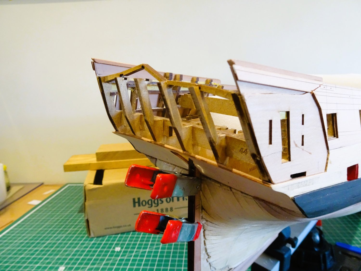
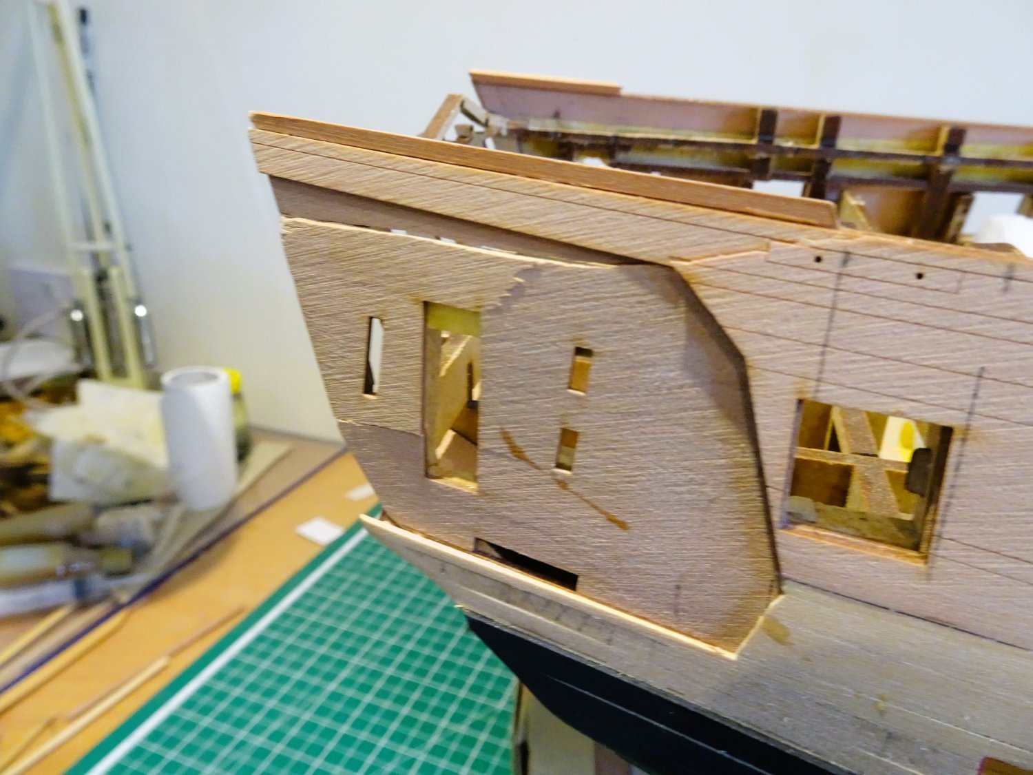
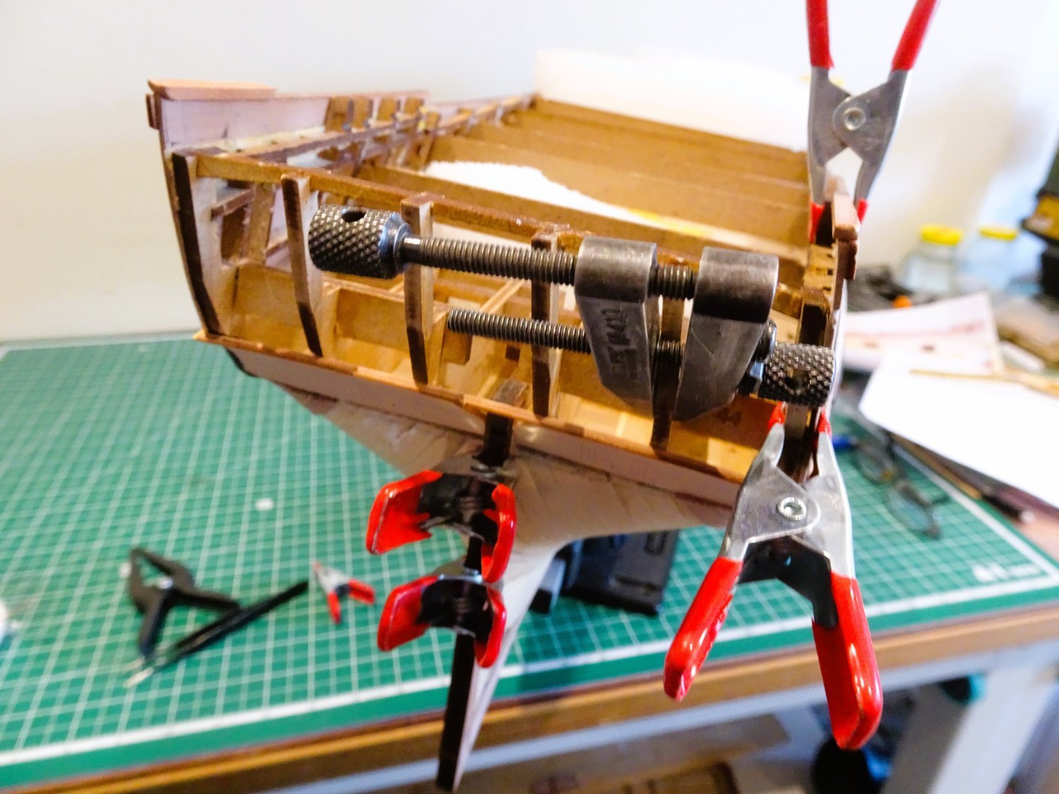
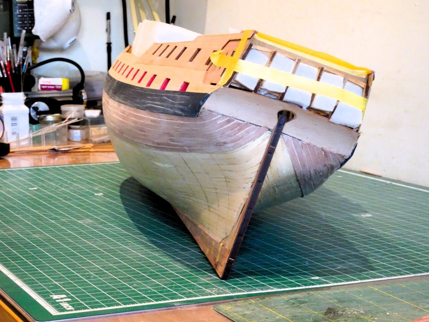
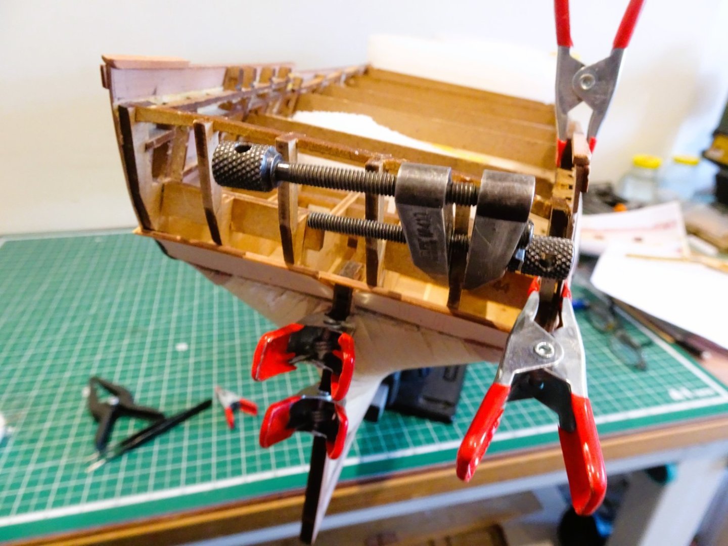
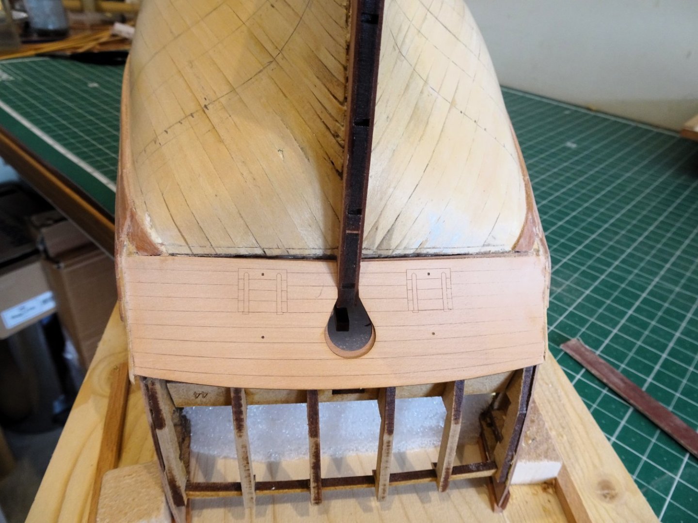
Post Forty-two A bit of a set back What I feared may happen with a hull this size has happened. Manoeuvring to check the lining off resulted in the hull toppling off its support with the stern crashing against the wall. 1185 The stern frame bracing has buckled, and one of the mdf stern frames split. 1186 The Upper stern pattern above the gallery has been split. 1187 1188 I’m bloody annoyed with myself letting this happen, but pva and clamps should sort the issue. Not a good start to the day.☹️ B.E. 16/06/2023


- 648 replies
-
- 22
-

-
-
-
- Indefatigable
- Vanguard Models
- (and 1 more)
-
Nicely planked Derek, that'll do very nicely. 👍 ps I like your idea of using pipe insulation for inverted hull support, an effective and lightweight solution. Regards, B.E.
-
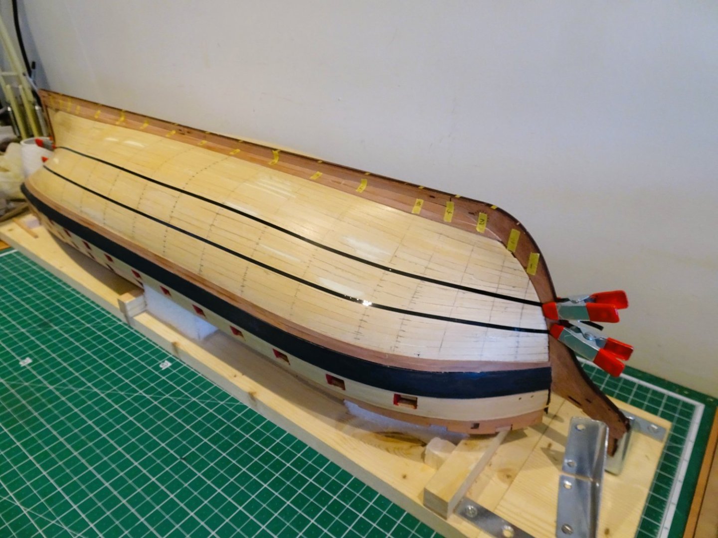
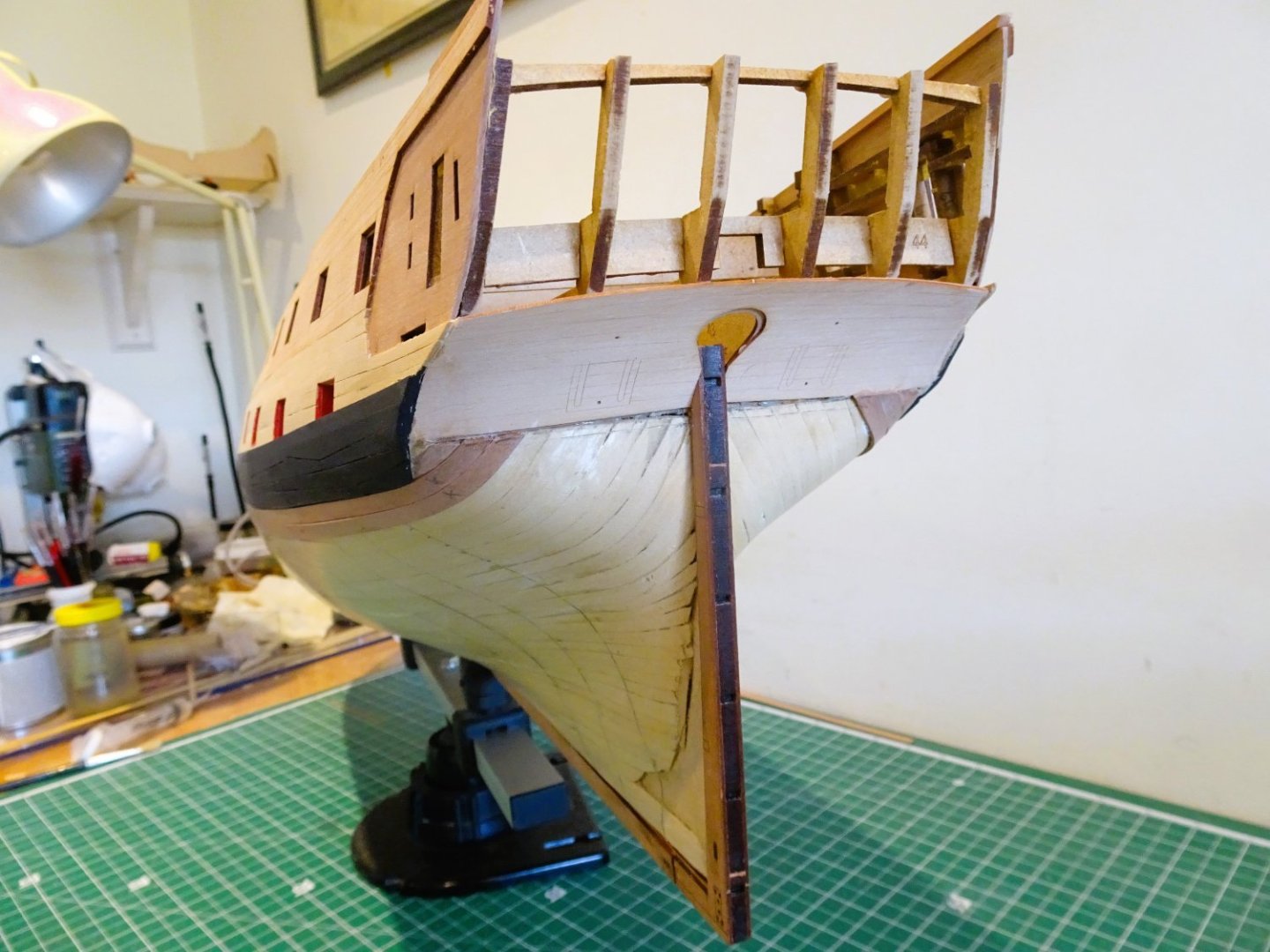
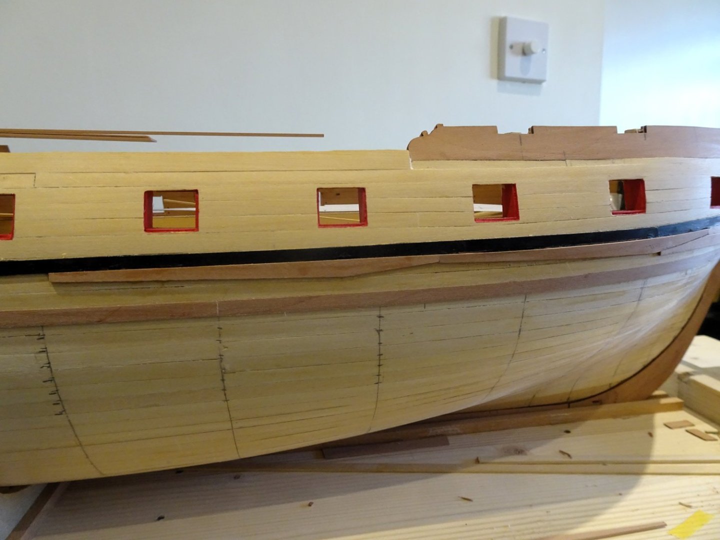
Post Forty-one Garboard Planks The two strakes below the wale are completed before I move onto the Garboard. 1152 These were fitted as individual planks, and attached using ca. According to the Construction and Fitting of the English Man of War (Peter Goodwin) the width of the Garboard Strake is 2/3 the moulded depth of the keel which would be 6.5mm at scale. At midships the depth from drop plank strake to keel is 141mm On paper this represents 28.2 number of 5mm planks. 1168 I have opted to round up to 7mm wide strips for the Garboard planks which I think better shows the difference to the usual hull planking. 1166 I next added the strake above the Garboard. 1161 1157 1165 At last, I can now move onto prepare for the remainder of the hull planking. B.E. 15/06/2023
- 648 replies
-
- 19
-
-
- Indefatigable
- Vanguard Models
- (and 1 more)
-
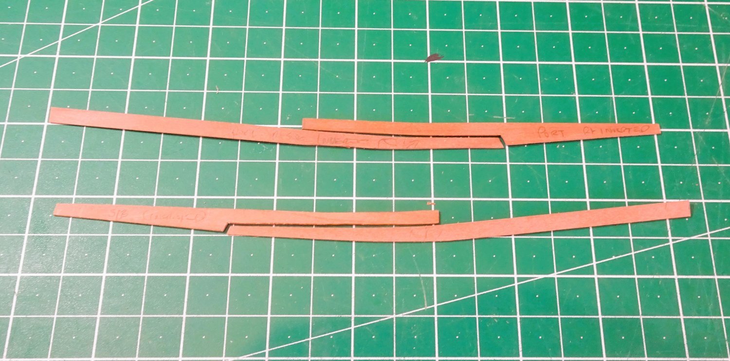
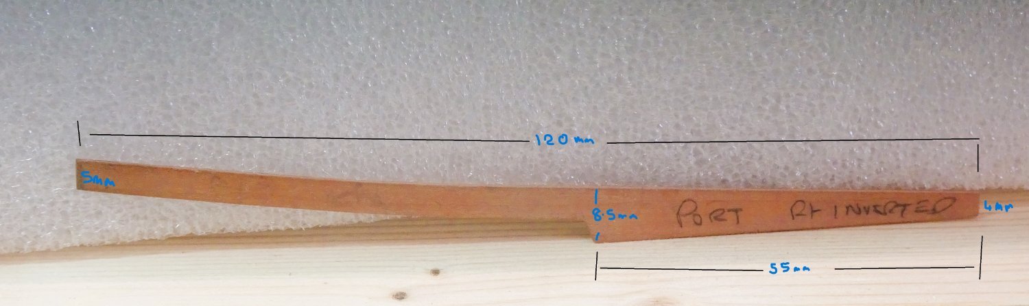
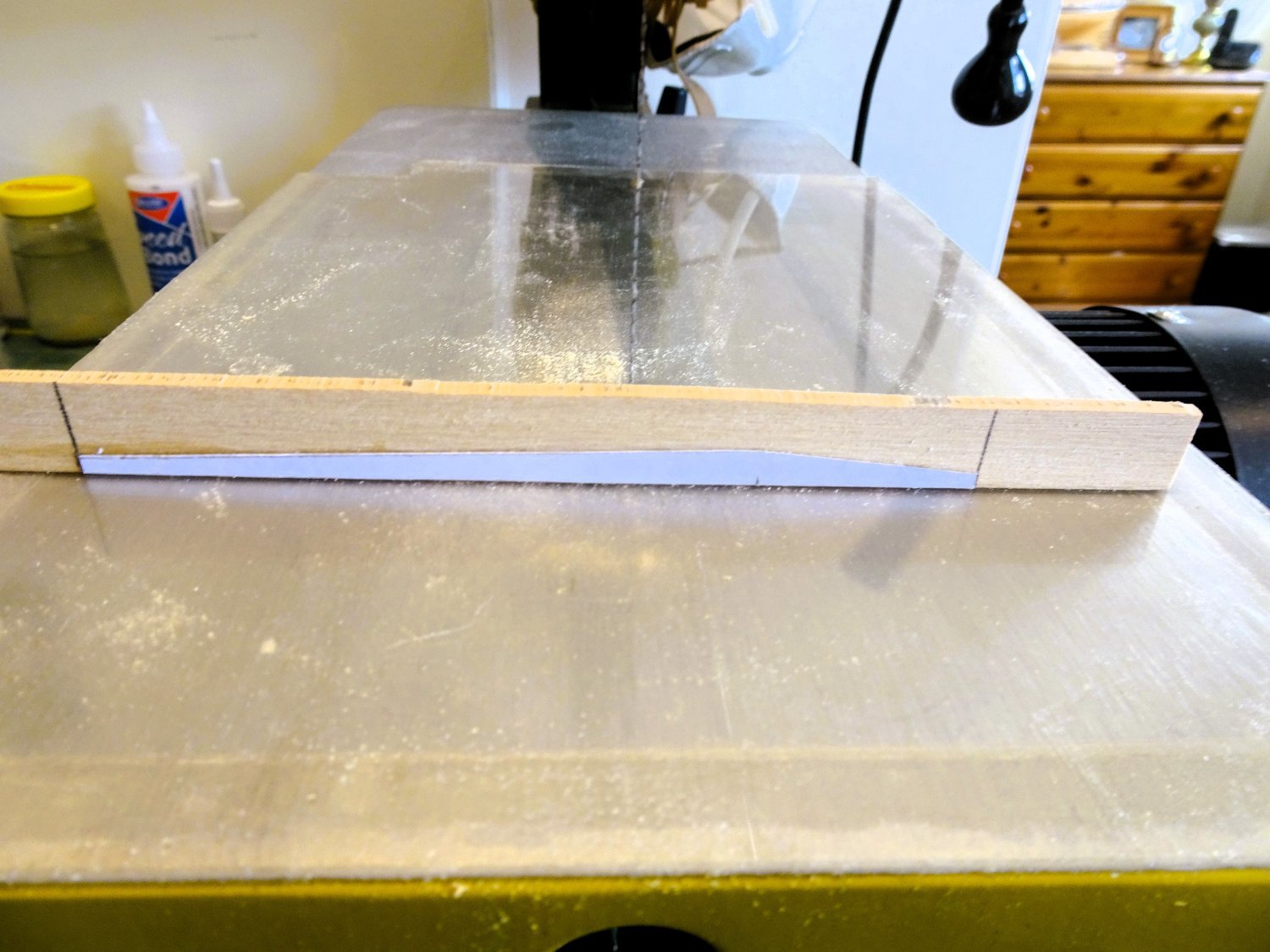
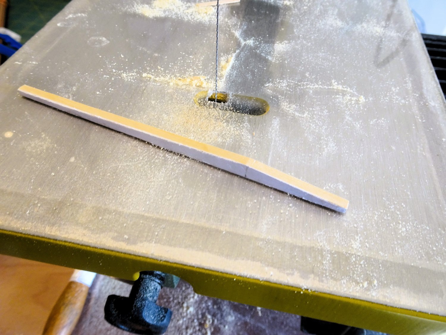
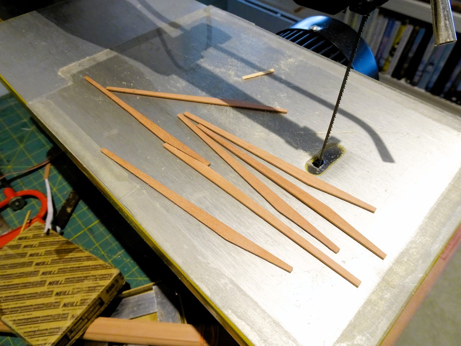
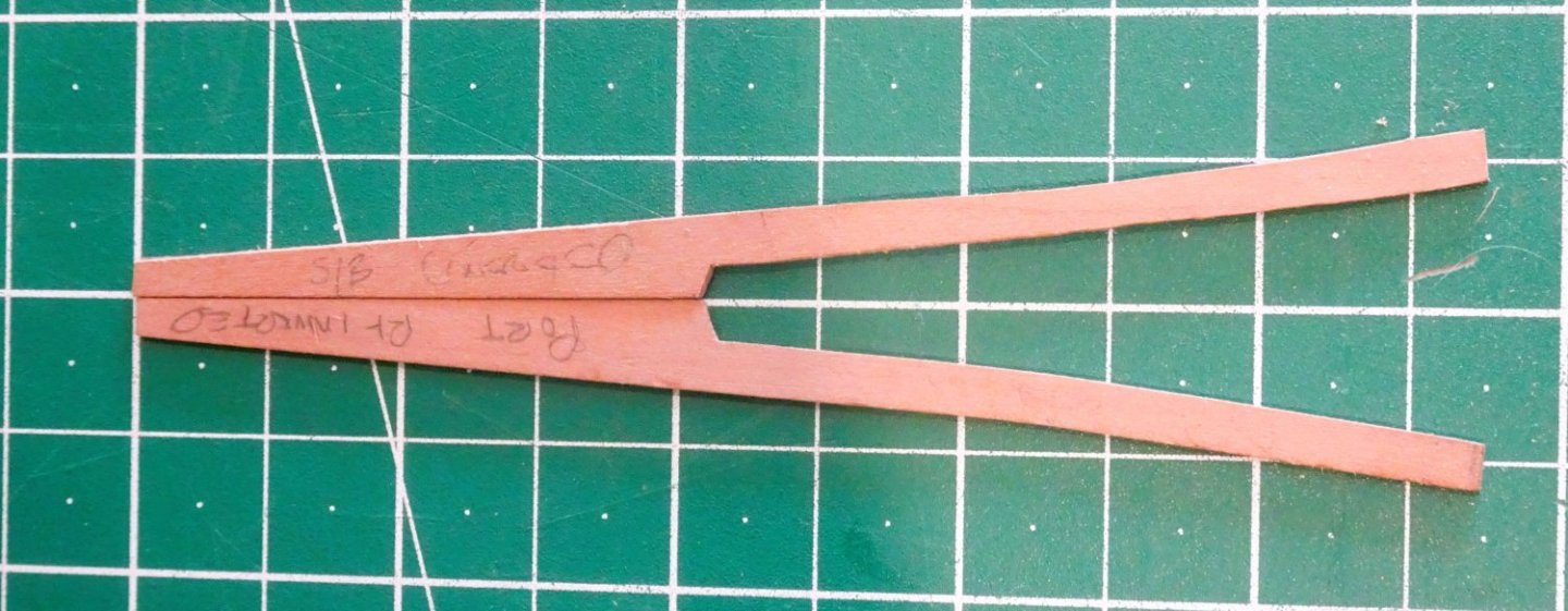
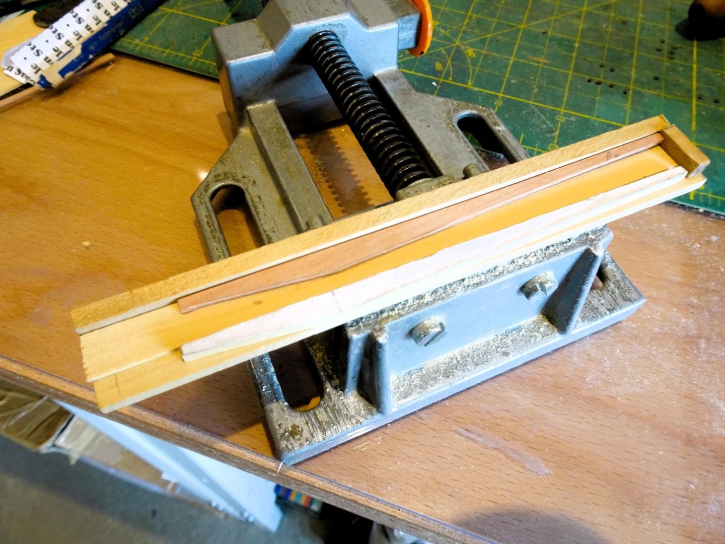
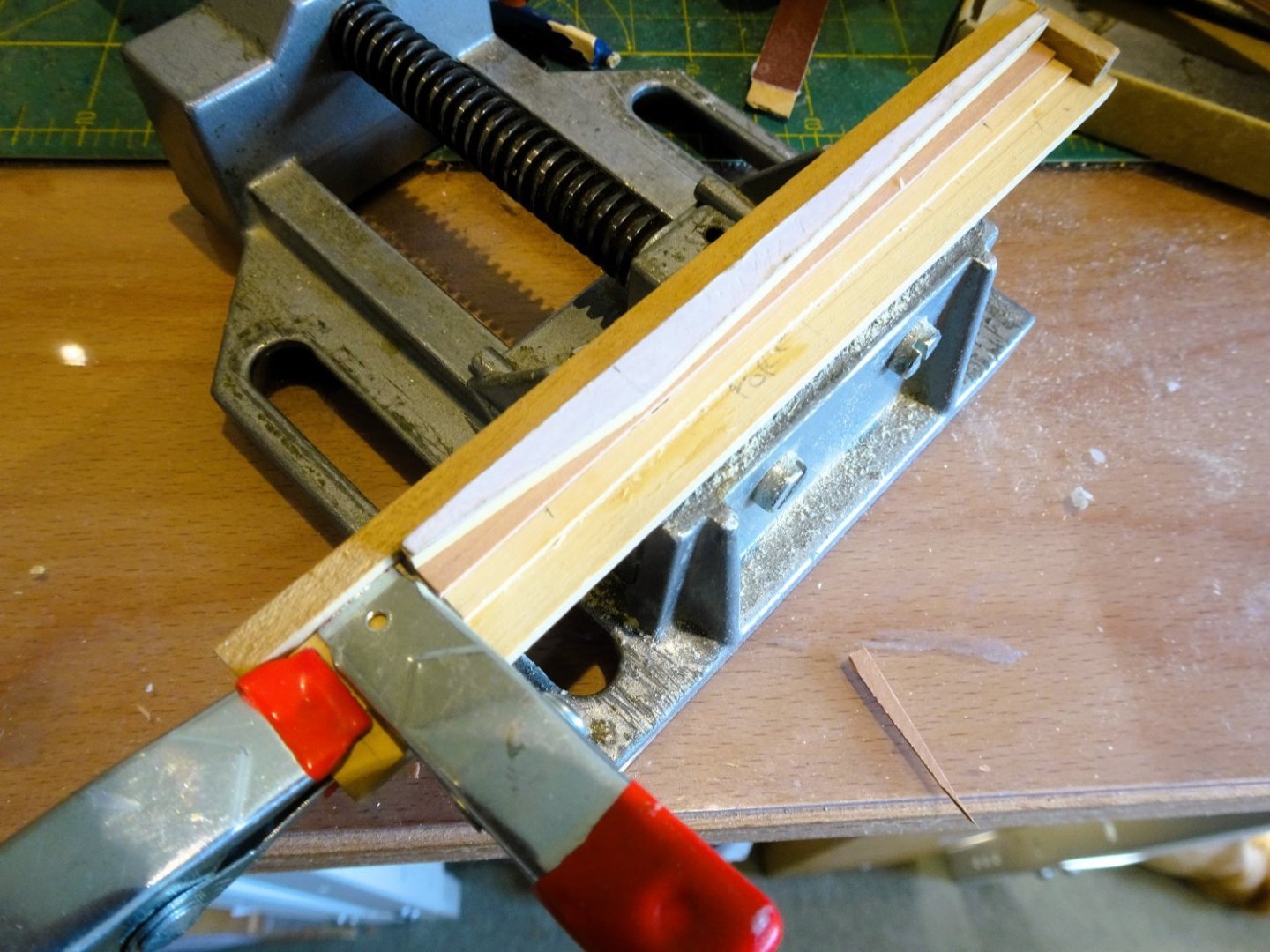
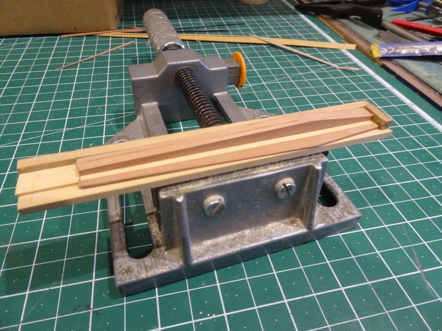
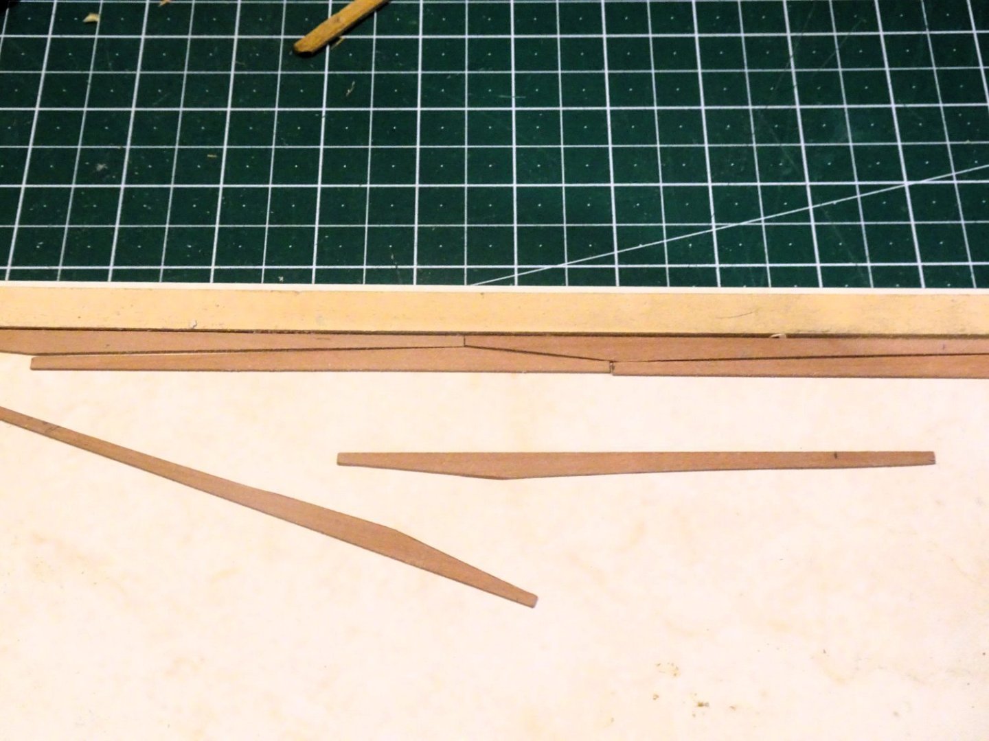
Post Forty Drop planks at the Bow. These are a feature of ships of the period and generally appear immediately below the wale. They are a nice feature on a model, and installing a drop plank should help prevent overcrowding of the strakes at the bow as planking proceeds. 1131 Where it meets the stem I have tapered to 4mm, which is 1mm less than the full single plank width. The taper was determined in the usual way using a single 5mm plank which was then use as a template on a 10mm plank. 1127 The body of the plank must be broad enough at the aft end to take account of a tapered plank that butts against it and runs beneath the wale. The tail of the Drop plank also must run to meet a full width plank of 5mm, following on and running towards the stern. Together they form the first two strakes beneath the wale. I couldn’t find any specifics about the proportions of drop planks between the body and the tail, so this is my best guestimate. 1128A These are the dimensions I used. The drop plank width is 4mm at the stem, 8.5mm at the aft end of the body, which is 55mm long, and with an overall length of 120mm. 1132 1133 1140 1148 1142 B.E. 14/06/2023


- 648 replies
-
- 18
-
-
- Indefatigable
- Vanguard Models
- (and 1 more)
-
I would agree with you Allan, the thinness of the davit struck me immediately when I built the launch for my Sphinx build. I doubled up on the kit measurements to allow for the inclusion of the roller, a fairly simple mod if the look offends the eye. PS. Alistair - I went for the Pinnace on the spare topmasts, I think the more elegant lines suit the Swan better. B.E.
-
A great result Jason, very nicely worked out, you have reproduced that elegant shape perfectly. B.E.
-
Post Thirty-Nine Completion of the Wales. The Port side planks were fitted without issue; the plank jig allowed for quick reproduction, and using ca, fitting was instant. I dampen the planks before applying the ca - it aids rapid grab. With both sides completed the hull is again inverted for finishing. 1107 The tricky part is the stern counter where the aft end of the wale is shaped for the round of the hull, and to follow the curve of the counter. 1112 It is important that there is a smooth transition between the lower edge of the wale and the plank below the wale that runs into the lower counter. All following planks of the second layer will follow this line. 1124 1125 1122 1121 1115 1120 I think there will be sufficient plank line definition to give a subtle impression of the Top and Butt once the wale is painted. 1118 I have moved quite a way from the oob sequence. For me the result is worth it, and by fitting the wale before the lower second planking I have the opportunity to work a Drop plank below the wale. Onwards.... B.E. 12/06/2023


- 648 replies
-
- 17
-
-
- Indefatigable
- Vanguard Models
- (and 1 more)
-
Cheers Guys, thank you for your comments, and ‘likes’. @ Alistair, - it’s a fine line (no pun intended) between showing the plank lines, and what looks like a poor fit. Worth doing regardless, as I know it’s there, and hopefully there will be sufficient lines showing thro’ to indicate the planks. 022 If I can achieve the result I got on Pegasus I will be satisfied. Looking out this photo I am reminded it has been twelve years since I last did a Top and Butt wale, where have all those years gone! B.E.
- 648 replies
-
- 7
-
-
- Indefatigable
- Vanguard Models
- (and 1 more)
-
Post Thirty-eight Main Wales With a supply of planks cut, application can begin. 1077 I start at the bow with a full-length plank, touch end to the stem. The planks will continue in this sequence to the stern. 1078 Below this a shorter plank starts at the touch and runs to the stem. The total depth of these two planks must be 8mm. 1079 I work both strakes sequentially as I go along, making minor tweaks as necessary. 1082 For the lower set of strakes I begin with the touch end starting midway along the foremost plank above it, to create a shift in the butts. 1085 This second set also starts with the straight edge upwards and continues in the same manner. 1093 The final plank of the lower strake is shaped to follow the curve of the hull and will be finally fettled as the wale is shaped to follow the transom line. 1090 Two days work and the Starboard side wale is completed. A lot less fiddly than Hook and Butt but still gives a more authentic look than straight plank Wales. 1099 The overall depth of the wale is 16mm around 3’ 4”. This is deeper that the kit wale by 1mm but is still slightly less that the depth given by Goodwin for a thirty-eight-gun frigate of 3’ 6.” 1098 1100 The wales will be cleaned up after the Port side have been fitted. B.E. 10/06/2023


- 648 replies
-
- 22
-
-
- Indefatigable
- Vanguard Models
- (and 1 more)
-
Thanks Glenn, the planks are the easy bit, it's the fitting that will confirm or otherwise my decision to go the difficult route.😕 ps; The Hoggs shoes are a bit like me, strong, tanned, and good for rough country,😉 The boxes are even better, perfect for a height extension to support the build board of a pocket Battleship. Cheers, B.E.
- 648 replies
-
- 3
-
-
- Indefatigable
- Vanguard Models
- (and 1 more)
-
Pure eye candy Glenn, thanks for posting those photos of your very fine work. Hard to pick out something for special mention, but but the result you've achieved with those gunport lids is top notch. No leaks through those ports. Regards, B.E.
- 840 replies
-
- 5
-
-
- winchelsea
- Syren Ship Model Company
- (and 1 more)
-
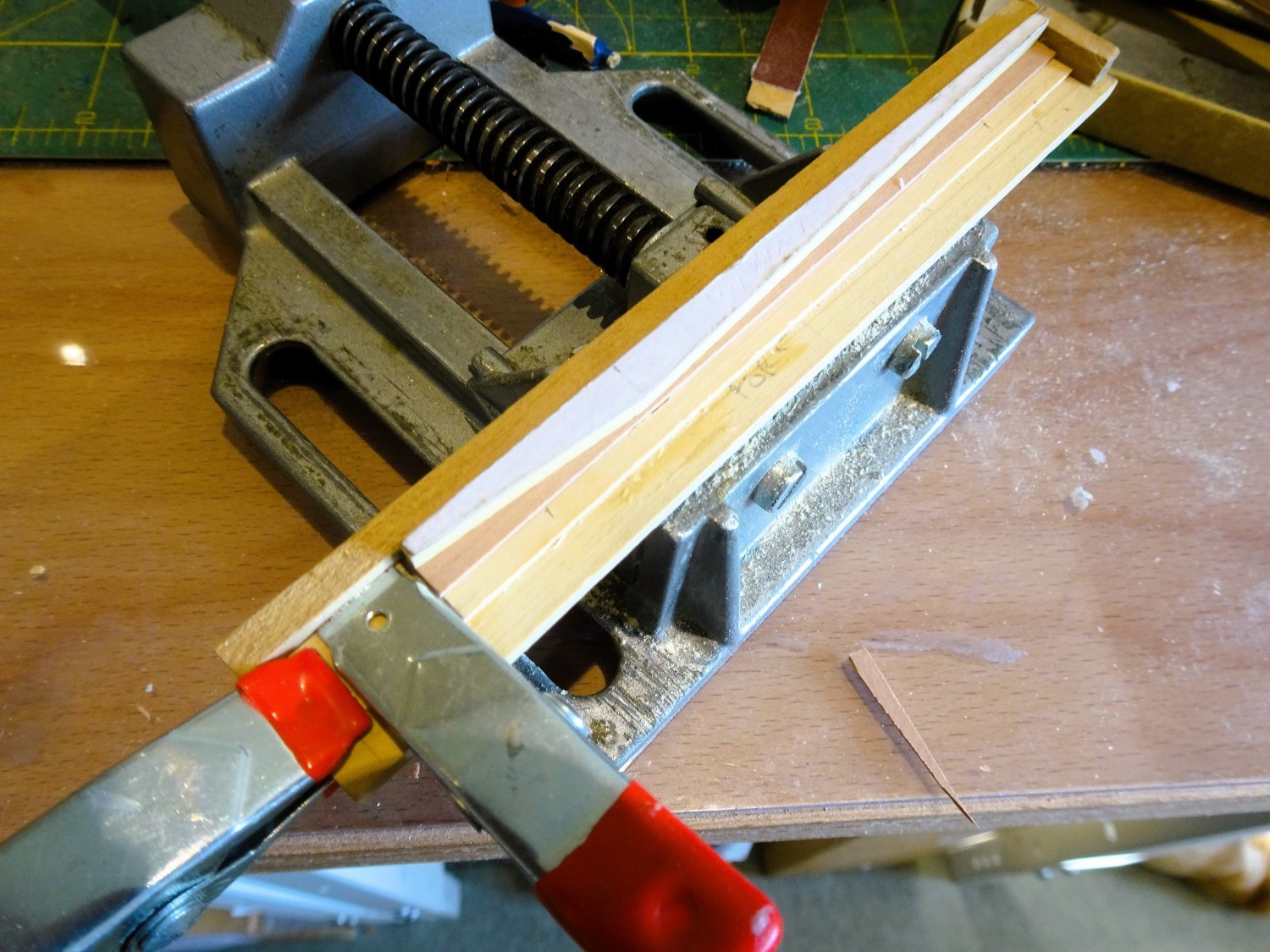
Post Thirty-seven Onto the Wales - The approach. 1062 A master plank was cut from some 6mm x 3mm Boxwood sheet. This will be used as a template to cut the planks. 1064 The planks are of a scale 120mm in length. The touch 30mm in from the end. (¼ of plank length) The touch depth is 2/3 the depth of the strake (8mm) = 5.33mm. The butts are ½ the depth of the touch =2.66mm. To make the measurements easier I used a touch of 5.5mm and a butt of 2.5mm, easier to see. 1068 A simple jig was made to hold the planks for marking and cutting. 1066 1070 I used 6mm x 1mm strip to form the planks. 1071 The trick is to ensure that all the joints will meet cleanly. 1073 Once the top wale strake is in place things will be easier, but the fit will be tested before gluing into place. I now need to cut around sixty planks – what joy! B.E. 08/06/2023


- 648 replies
-
- 15
-
-
- Indefatigable
- Vanguard Models
- (and 1 more)
-
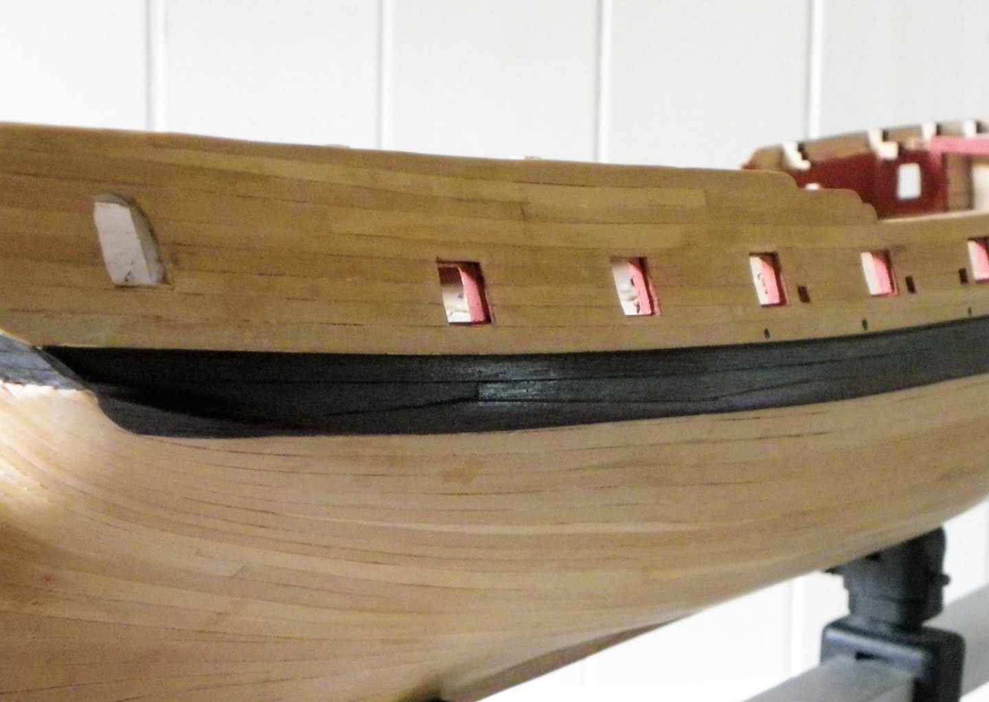
Thank you, Nils, and Kevin, and for the ‘likes’. Post Thirty- six The Black Strake My plan is to fit the wales, followed by a drop plank, followed by the Garboard plank, followed by lining off and planking the remainder of the hull. If only it was as simple as those few words. The first task is to fit the Black strake which will fix the line of the wales. For this I am using 0.8mm x 4mm Pear. 1061 The kit indicates use of 1mm pear, but I used 0.8mm as I think it better reflects the subtle difference in thickness between the wales and topside planking. 1059 I used Vallejo black to colour the strake before fitting but may tone it down using Black/grey, depending on the overall effect. 1056 Masking tape was used to mark the upper line, and Ca was used to apply the strakes. 1048 Onto the wales and a somewhat trickier operation. B.E. 07/06/2023


- 648 replies
-
- 23
-
-
- Indefatigable
- Vanguard Models
- (and 1 more)
-
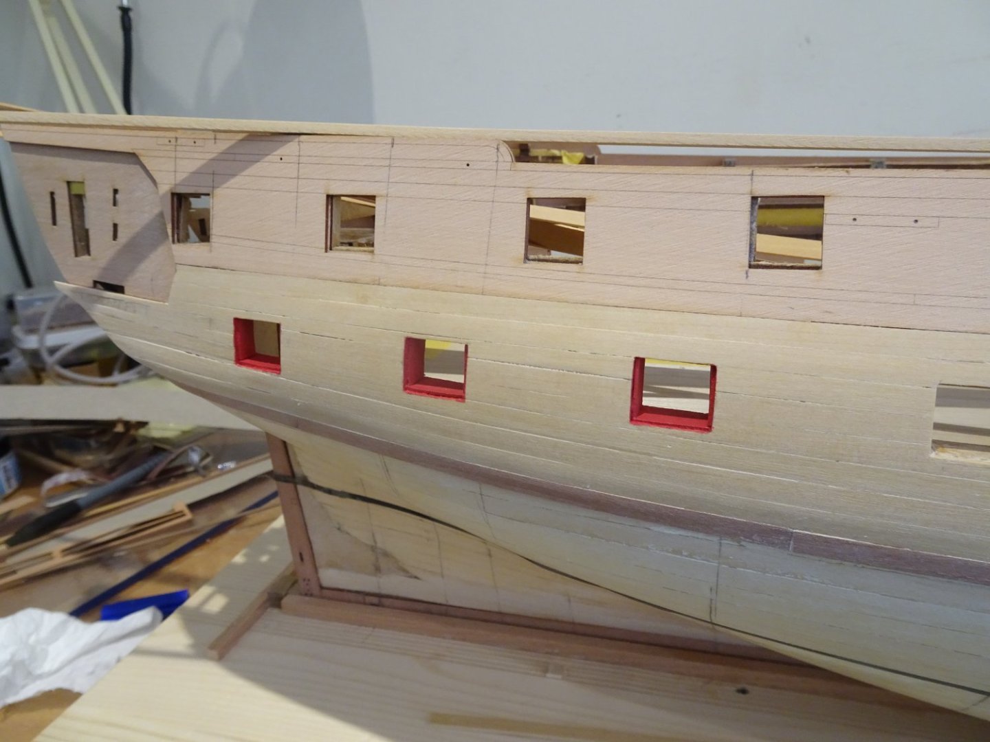
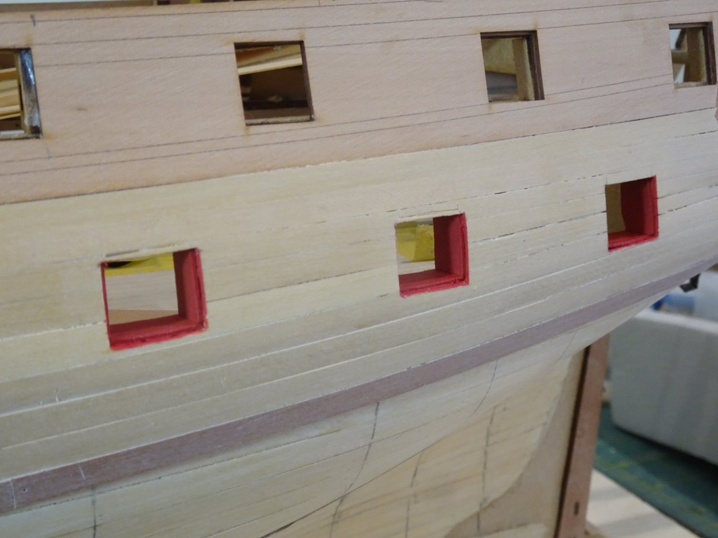
Post Thirty-five Port Lining continues. I am using 0.6mm Boxwood (10mm wide) to line the remaining gun-deck ports. If nothing else it will provide a smoother finish than sanding the mdf /lime/pear/ sandwich which make up the bulwark. 1025 The bottom layer goes in quickly using the kit part as a template, and simply requires trimming on the inboard side. 1021 The kit part 549 was used as template for the more complex side pieces. This was simply transferred to the Boxwood strip and cut to suit. 1023 The ports were re-taped for painting. I think I should buy shares in Tamiya tape, I use so much. 1037 1035 1043 1027 1032 The whole process went more quickly than I had initially thought, four days to line the ports and apply a couple of coats of paint. A few ports will require a little more attention, but that is something I will return to, as is attending to the inner bulwarks. Onwards to sorting out the wales. B.E. 06/06/2023


- 648 replies
-
- 24
-
-
-
- Indefatigable
- Vanguard Models
- (and 1 more)
-
Thank you Nipper and Allan. @ Nipper - Nice of you to say so, but I don't think I deserve mention in the same company as Chuck, I might qualify to sweep up in his workshop, and I'd be happy to do that just to watch him. (Can you tell I'm a fan 😄) @ Allan - I'm using 0.6mm stuff which equates to 1½" about right I think. The side stops are fitted on the bottom stop, which I find easier to do. Cheers, B.E.
- 648 replies
-
- 2
-
-
- Indefatigable
- Vanguard Models
- (and 1 more)
-
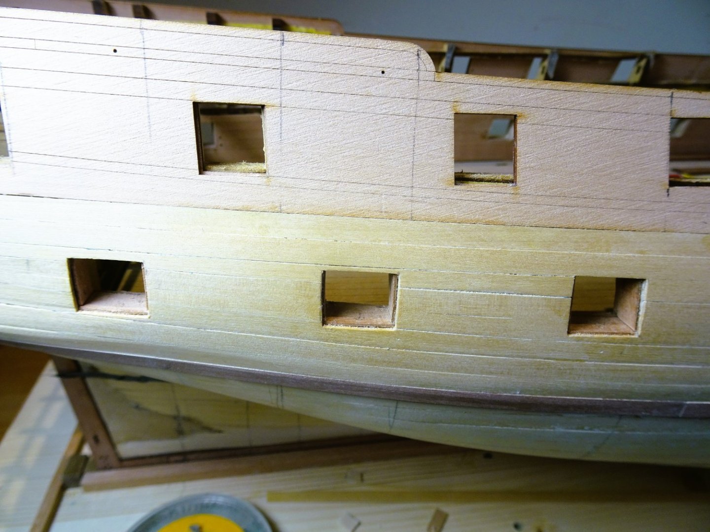
Post Thirty-four Topside work continues. Having eventually squared (or rectangled) the gunports, I turn my attention to lining the ports. Notwithstanding that there has been a deal of discussion on the forum as to how these were formed and where deployed, Chris has provided the makings for the linings or stops, pre-shaped for the angles involved. Only the foremost and aftermost three ports are catered for but the pieces do require fettling to fit. Fiddly little beggars to fit but perhaps an easier option than using the outer planking to form the rebate. I did find the depth of the parts was a little narrow to meet the inboard edge of the port, whether this is a design simplification I don’t know, but the usual practice was that the stops abutted the inboard framing and were then boarded over with the quick works and spirketting to the edge of the port. The frets provide useful basic patterns for these parts, to replicate linings, and I will keep the frets as a template for future use. 1001 The thin 0.6mm board required bracing during fitting to prevent curl. 1008 It’s a slow business fitting the linings. 1007 A piece is provided for the top of the port opening, but these were not fitted in practice, and I will leave them off, saving me a little effort. 1009 The ports are masked to apply a first coat of paint. I don’t want any bleed onto the outer woodwork, as this won’t be painted. 1010 1013 The masking seems to work well, keeping the paint line within the rebate. 1016 The macros show minor gaps that require filling, and rough areas that require smoothing before repainting. I have decided to line the remainder of the ports, I think they look better, although it probably adds up to another weeks work. Moving on - if slowly. B.E. 02/06/2023


- 648 replies
-
- 21
-
-
- Indefatigable
- Vanguard Models
- (and 1 more)