
HOLIDAY DONATION DRIVE - SUPPORT MSW - DO YOUR PART TO KEEP THIS GREAT FORUM GOING!
×
.JPG.ca33079f5815b861e67b9c2cccd37982.JPG)

Blue Ensign
-
Posts
4,564 -
Joined
-
Last visited
Content Type
Profiles
Forums
Gallery
Events
Everything posted by Blue Ensign
-
 Cheers Guys, Nice of you to say so rkwz, but I think it would be too expensive, and besides you get access to all the photo's in the build log for free, glad you like them.😃 B.E.
- 335 replies
-
- 1
-

-
- alert
- vanguard models
- (and 1 more)
-
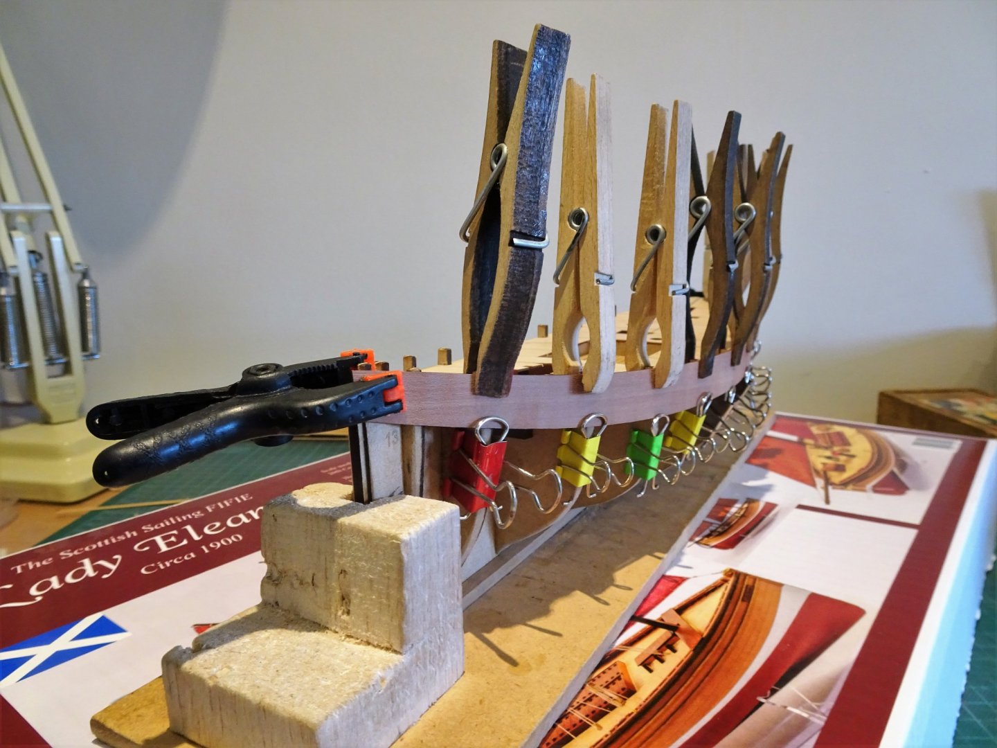
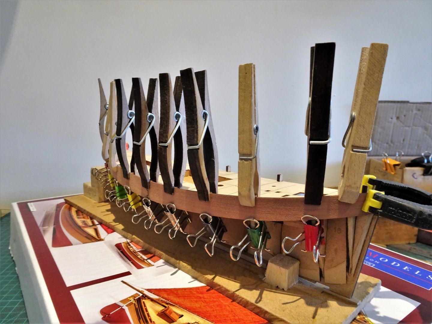
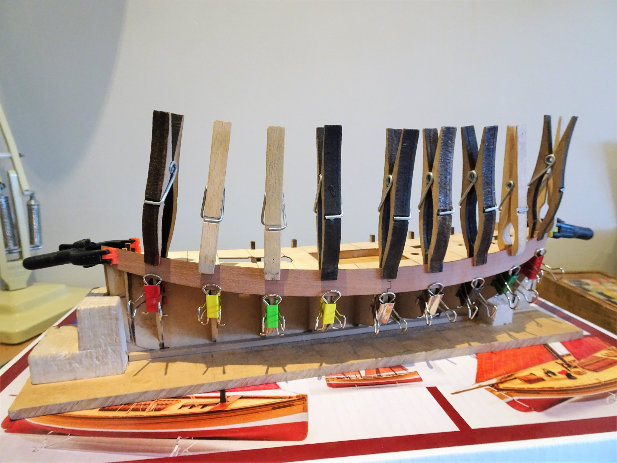
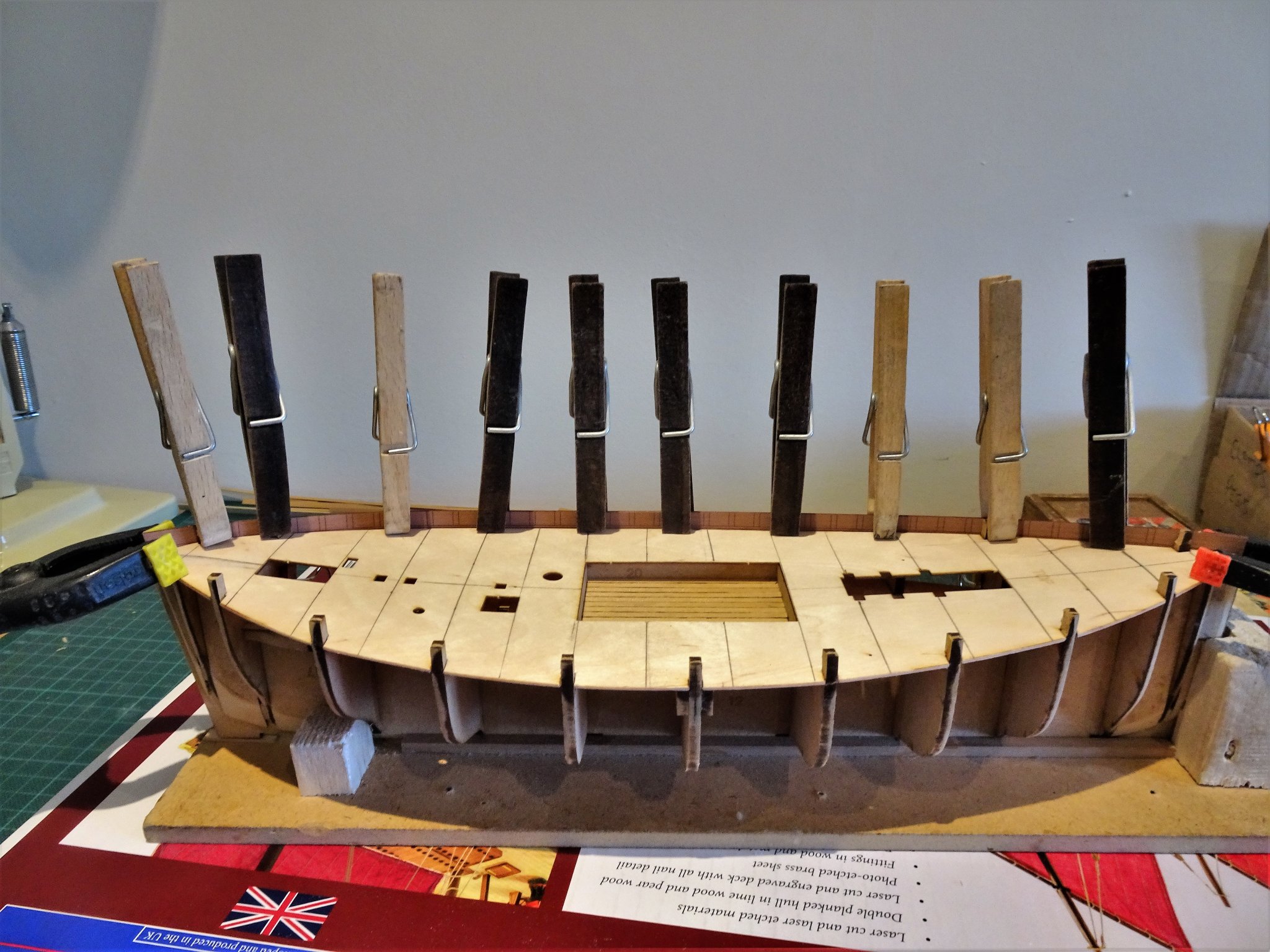
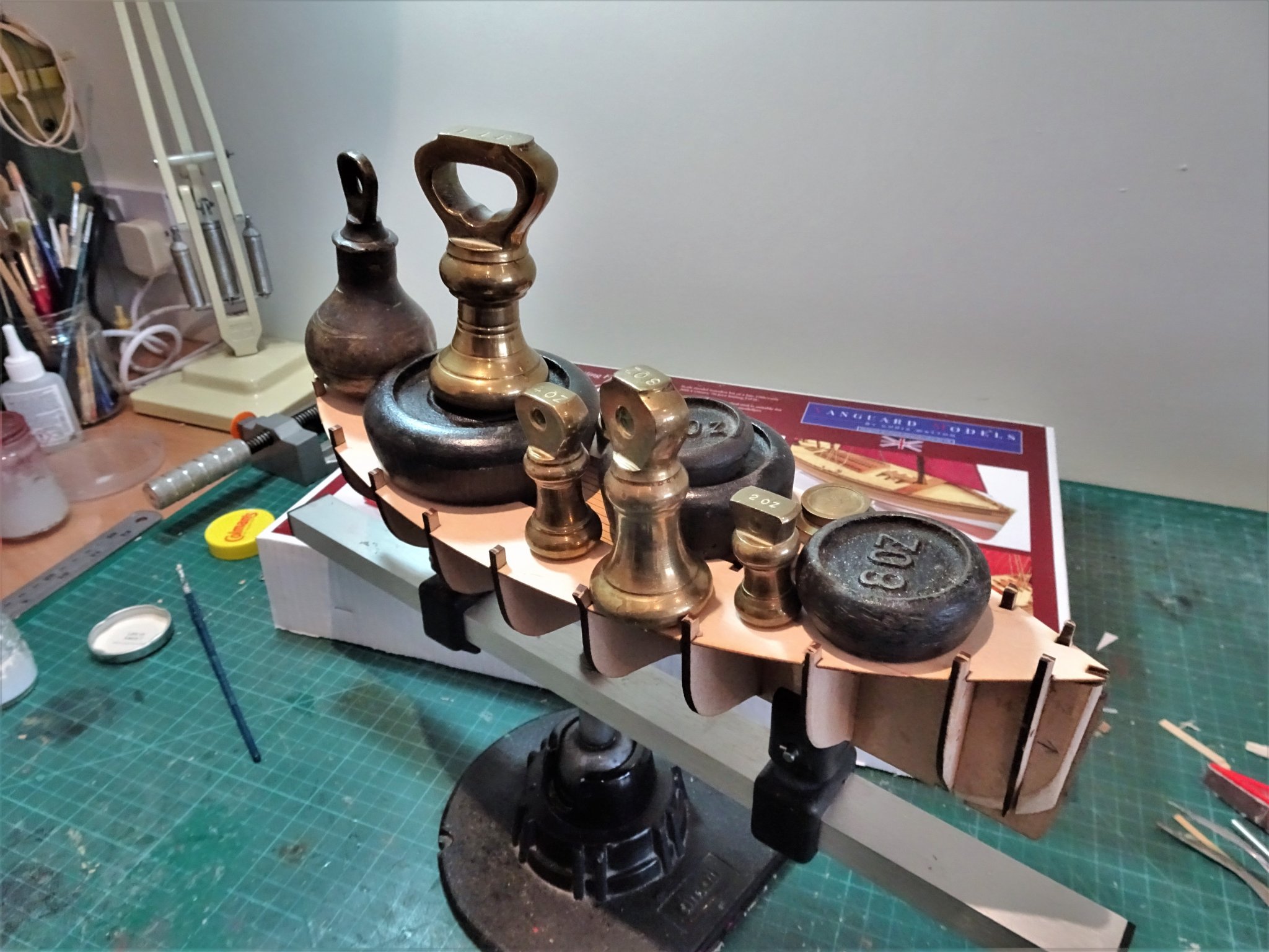
Post 4 Bulwark Preparation and fitting Fitting bulwarks is often a tricky part of a build. The Fifie ones are simpler than many and I like the way Chris has etched the fitting line on the inside to assist the process. The parts are marked as left and right, or port and starboard looking from stern to stem, and contain etched markings for the locations of the inboard timberheads. 5178 I soaked the pieces in hot water as suggested, but once temporarily fitted to impart the curve, I also gave a blast of hot air from the hairdryer. 5181 Holding the bulwarks in position against the bulkhead tabs is easy. Holding the bottom edge against the bulkheads less so. 5184 I used the converted Fold back clip method. I think Amati have brought out an enhanced version, as shown in James’s log. 5187 The deck has been marked with beam positions and a centre line against which the planking will ultimately be laid. 5226(2) With the required curve achieved, fitting is relatively straightforward, just ensure that the fitting line and joint are properly aligned. 5229(2) I did find that the fold back clips weren’t quite strong enough to hold the bottom edges firm against all the bulkheads when it came to gluing, particularly where the two pieces joined. Use of the provided brass pins resolved the situation, but a pin pusher is advisable. 5231(2) The cutter-like sheer is clearly apparent in this photo. With the bulwarks now in place, the first planking can commence. B.E. 23/05/20

.thumb.JPG.9164c82eb1f15605057eaf43983c40cf.JPG)
.thumb.JPG.e787b837b980ee9f79784d01a7f1e233.JPG)
.thumb.JPG.7261740e102e78151ccce361e0ca8dd3.JPG)
- 195 replies
-
- 17
-
-
- lady eleanor
- vanguard models
- (and 1 more)
-
Well done David, a fine looking model. 👍 B.E.
- 145 replies
-
- 1
-
-
- model shipways
- charles w. morgan
- (and 1 more)
-
Alert is completed but remains uncased as this is presently stuck down in Devonshire for the duration. Not too much of a problem as Alert is not so heavily rigged as to present dusting issues. To amuse myself during this covid19 lockdown I put together a build album. Something I also did for Pegasus, and Cheerful. 5208(2) 5200(2) 5206(2) Passes the time and creates a nice record of the build. 5214(2) These are three pocket sized albums that I usually order along with the larger versions. B.E. 22/05/2020
.thumb.JPG.b420f68470566c6fbd8c2656a46b6ec8.JPG)
.thumb.JPG.6995812842f3422caaa5a79018fa4bfb.JPG)
.thumb.JPG.b6fed03d2053aabe87a6155bb3ea9f79.JPG)
.thumb.JPG.223062120a8e083d1c77ceb4d1f2f5af.JPG)
- 335 replies
-
- 16
-
-
- alert
- vanguard models
- (and 1 more)
-
Cheers Guys, @ spy – can’t help myself, not good odds spy. 😃 @ Jason – I can’t see much evidence of cross graining on the maple veneered etch, it appears a very fine and straight grain, but I don’t know at this stage whether applying matt varnish would reveal anything. I will have a final chance to look at the etched deck once the hull has been completed. @ Glenn – when you’ve always had to plank decks, imperfect as it may or may not be, it’s hard to change, but it will be useful to see when the first batch of models, using the etched decks are completed. @ Derek – Well said, and a good point, I had the same thoughts myself when I built the Alert kit. However, once a kit is out there it is up to the builder to report as they find, modify to their own satisfaction, and it is for others to take from it what they will. Chris has made a major contribution to the ship modelling world, I’ve thought, and said so, since I built his Pegasus designed model for Amati. All of the Vanguard range of kits are very appealing, and some of the best I’ve seen, particularly from the point of view of builders new to the hobby. Chris has put a great deal of effort into the kits to provide a good oob experience for the first time builder. @ Bob - weathering is a tricky business, and I don't think I'll be going there either, except in a very subtle way in some areas, I've just got a feeling that a laid deck will suit the model type better, we shall see.🙂 B.E.
- 195 replies
-
- 5
-
-
- lady eleanor
- vanguard models
- (and 1 more)
-
Beautiful work Thomas, a great addition to your build, love that boat👍 B.E.
-
Thank you Yves, a laid deck will obviously look more natural, and in my case certainly more in keeping with the build which won't match the purity of the etched deck. It remains to be seen whether I made the right decision once I have completed the large amount of nibbing involved. There may be a lot of loose nets lying around the deck. 😉 B.E.
- 195 replies
-
- 7
-
-
- lady eleanor
- vanguard models
- (and 1 more)
-
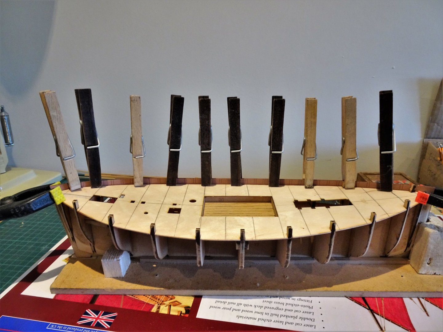
Thanks Dave, and Glenn,😃 Post 3 Fairing and Second thoughts The bulk of the chamfering is on bulkheads 1 – 3 and 9 – 11 and the infill pieces also need additional fining down to suit. Less fairing is required on bulkhead 4 and 8, and barely any on bulkheads 5,6, and 7. But the sanding needs to create a smooth run across all bulkheads at all levels, using a strip to check, and the process did take me longer than the suggested hour for this work. 5156 The whole structure is rock solid now, and fairing on this shaped hull is about as straightforward as it gets. Thinking about decking - A pause for thought The kit provides a very nice etched deck which I initially found appealing, thinking that will save me the bother of doing it myself. 5153 However, I find myself getting less enthused about it, and if I’m going to change my mind I need to do it now before I fit the bulwarks, so I can more easily mark out a decking plan on the base deck. I think the primary issue for me is that it looks a little too neat and navy fashion with a regular three shift butt pattern for what would be a humble and cheaply built fishing boat. Once these thoughts get into your mind it’s hard to dismiss them. Those new to the hobby, and this kit is really directed at that market, will no doubt find its inclusion of great benefit, but it is a kit that also allows us serial interferers plenty of scope to go our own way.🙄 5150 With an overall deck length just shy of seventy feet, and a large hatch midships the need for plank butts is very much reduced, as most planks within the area are well within the maximum lengths available for single runs up to the nibbing, both fore and aft. The longest scale planks on the etched deck are 80mm, a tad short of 17’ At this point I don’t actually know how these small boats were decked but I suspect that it was possibly slightly more random, using available timber to the best effect to keep costs down. The builders would presumably still adhere to good practise of not having adjoining butts on the same beam, or adjacent butts too close to each other. There is also a scale aesthetic to be considered so that any pattern doesn’t look unbalanced on the model but I think the model can be reasonably planked with far less butt joints than indicated on the etched deck. 5149(2) Fore and aft of the fish hatch within the bounds of the coamings the maximum uninterrupted plank run is 23’ (110mm) and it is not really necessary to have butts until outside of the hatch coaming line. 5155 An important factor is that I do have the makings to deck out the model ( Boxwood strip 0.6mm x 3.4mm as used on the lower deck.) So, I’ll take time out to review the situation and before I move on see if I can come up with a plan that pleases my eye. B.E. 20/05/20
.thumb.JPG.2d3bf4e4a78044d493b4cd9685539591.JPG)
.thumb.JPG.1dff9f09af481f45e0ccb8dcf5328059.JPG)


- 195 replies
-
- 18
-
-
- lady eleanor
- vanguard models
- (and 1 more)
-
The head rails look great Derek, certainly a cut above some I’ve seen on kits, and together with the stern are key features on a model, very nicely done. Interesting discovery about the etched deck, but if you’re not happy you are best to take the long route and individually plank. At least you have a laying pattern already worked out. I’m off to scrutinise the etched deck on my Fifie now 🤔 B.E.
-
Thanks James, testy is a relative term 😃 @ Chris, the deck is of excellent quality, I think I was more concerned about the bulkhead tabs, there can't be that many circumstances when the deck would have to come out again, but I wouldn't like to have to do it. I am really impressed by the accuracy of the fitting of the parts thus far. 👍 B.E.
- 195 replies
-
- 7
-
-
- lady eleanor
- vanguard models
- (and 1 more)
-
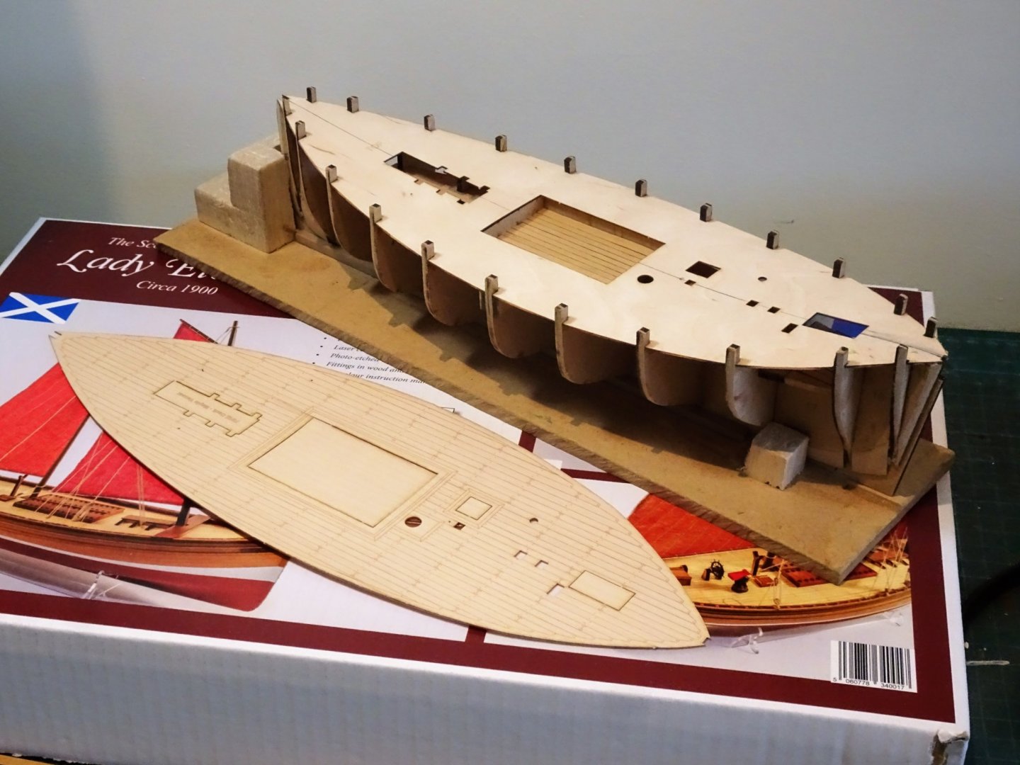
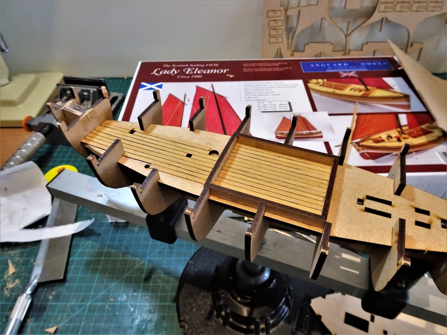
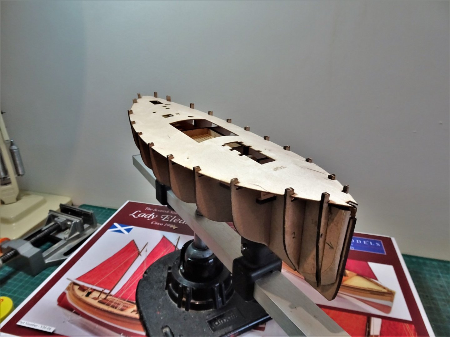
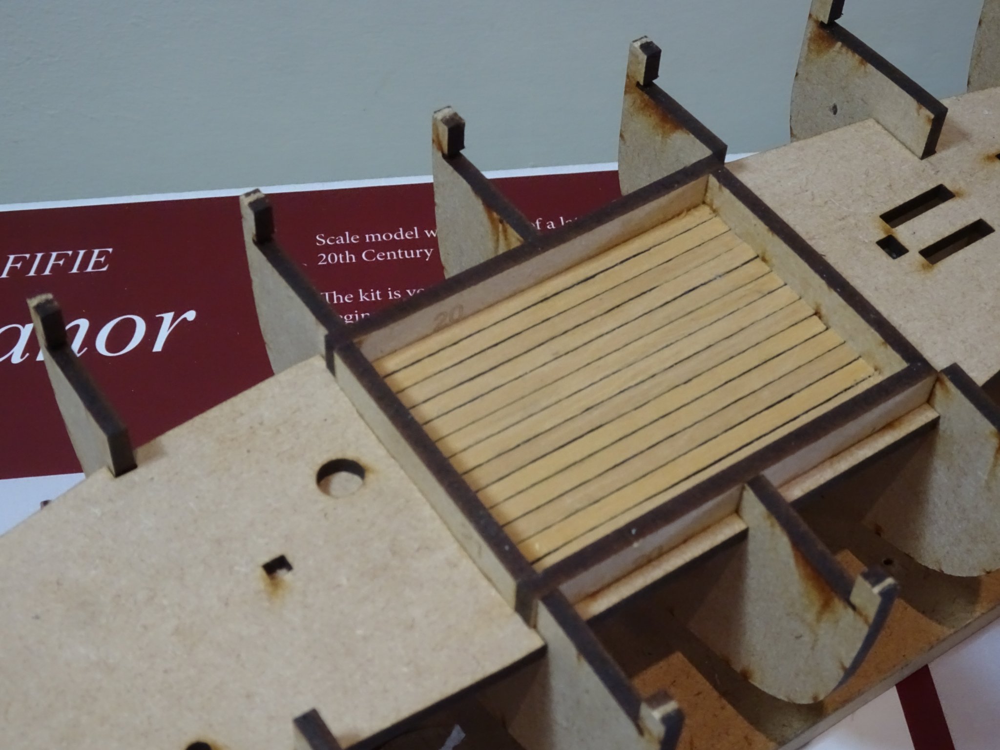
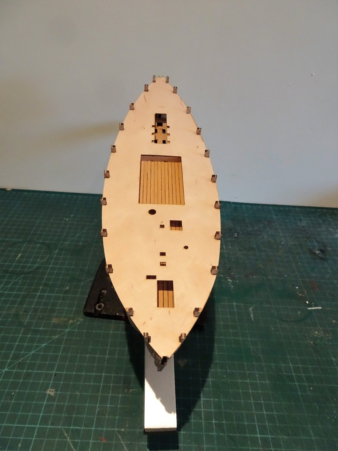
Post 2 Basic assembly continued. Simple assembly continues with everything fitting together as perfect as a jigsaw puzzle without anything puzzling. Follow the manual and you can’t go wrong, Chris’s many years of experience as a designer and builder show through. Everything is numbered, everything is clear. For the novice builder there are no headaches here. At this stage I bring a support board into use. 5122 I used the slightly modified board I used for the Alert build, the two hull lengths are not that different. The Fish hatch framing slots into place on the lower deck with a precision fit. Well it didn’t last long into the build, but at this point I make a minor modification. None of what follows is necessary, or has any real impact on the build, but I can’t help myself, and one of my foibles is that I like to have a glimpse of below decks, which I feel adds interest, and gives an impression of depth to a model. 5124 Firstly, I boarded out the lower deck within the Fish hatch framing, with 0.6mm boxwood strip on the basis that I don’t know at this stage how much of the hatch cover I will eventually leave open. I also may wish to open the sliding companionway roof or doors. 5128 To this end that section of the false keel between bulkheads 9 and 10 needs to be removed and an extension to the lower deck fashioned, easily done using spare mdf from the parts framing. 5129 This completes the extent of my lower deck planking. 5132 I coated the bulkhead surfaces with slightly diluted pva and slotted the sub deck into place. I found it best to slot one side partly into place, flex the deck up, and tease it into the other side. 5134 This is a little tricky and one of the bulkhead tabs did break off during the fitting, and once in place in the designated slots I still needed to weight and use elastic bands the hold the deck down at the edges. I think getting the deck out again would be a fraught business risking splitting the deck and breaking tabs. 5147 Next morning I also painted diluted pva on the underside of the deck along the bulkhead join. 5143(2) There is a fair bit sheer on a Fifie. This completes the basic carcass assembly; things will get a little more testy in the next phase of the build. B.E. 19/05/2020


.thumb.JPG.5777712f39f3112711924853a1499afb.JPG)

- 195 replies
-
- 24
-
-
- lady eleanor
- vanguard models
- (and 1 more)
-
It's a pleasure Yves, and probably the best photo the build will show. 😉😃 B.E.
- 195 replies
-
- 6
-
-
- lady eleanor
- vanguard models
- (and 1 more)
-
Thanks Bob, William is his name, quite experienced in shipyard matters, has been with me through six builds. 😃 I think Chris has done a great job with these small fishing boat kits, ideal for novice builders, and giving a first build high level of satisfaction, which is a main driver for folks to continue in the hobby. Regards, B.E.
- 195 replies
-
- 4
-
-
- lady eleanor
- vanguard models
- (and 1 more)
-
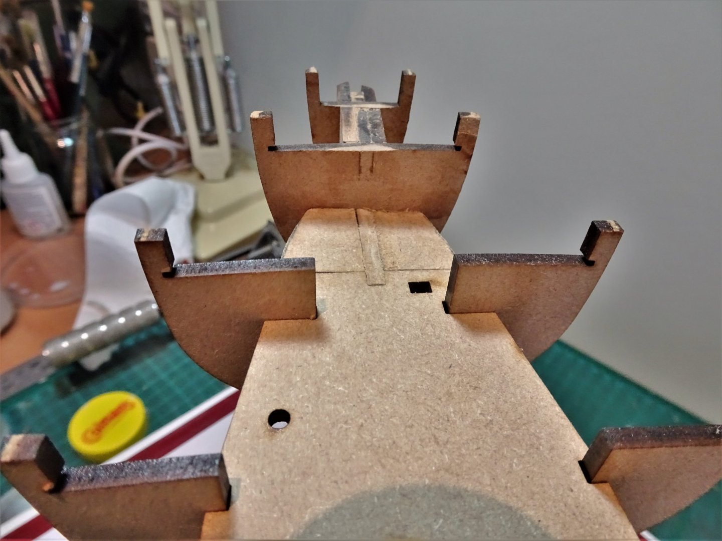
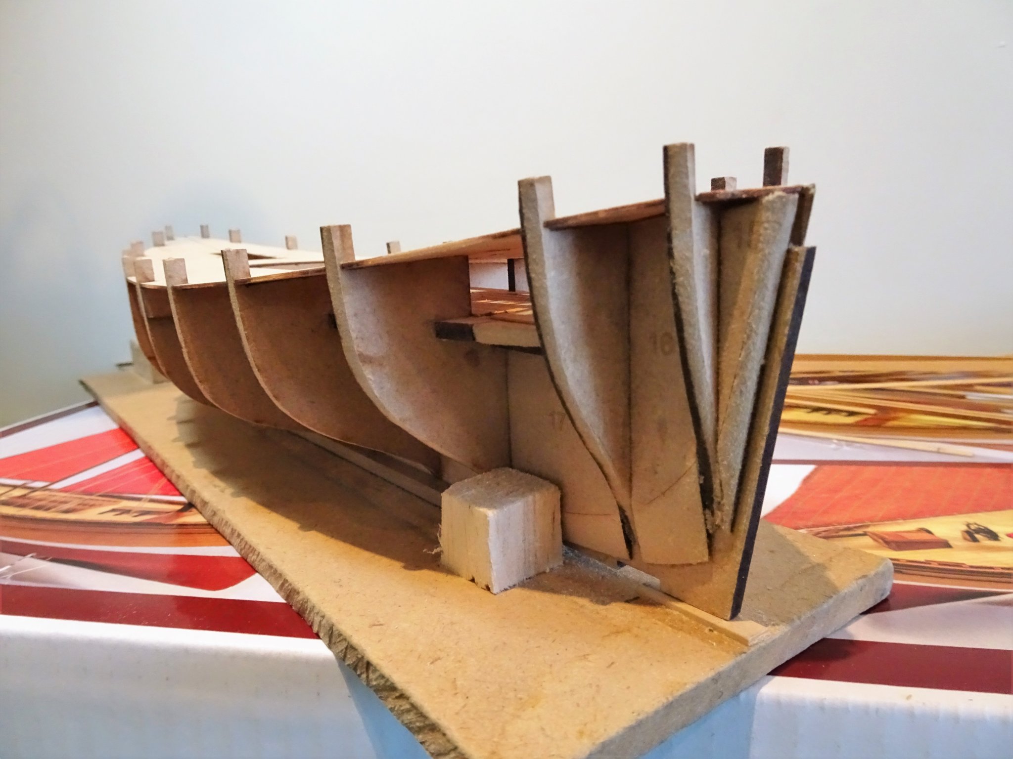
Post 1 I have started the build, but much of the early stages are hardly exciting and my shipyard assistant is not particularly enthused to be brought back off furlough. 0024(2) I have assured him that this is not likely to be a prolonged contract and he can soon get back to more spaniel related interests. Bulkheads and false keel The bulkheads fit to the false keel beautifully, just the right tension necessary. I couldn’t trust myself with a Dremel to do the pre- bevelling on the fore and aft bulkheads but a sanding stick worked just fine. I didn’t want to risk breaking off the fine points on bulkheads 1 and 11. 5119(2) The infill pieces also require bevelling and these are perhaps the most tricky ones to do. I found that a No 11 scalpel worked best for me, cuts thro’ the mdf like a knife thro’ butter. They were then finished off with a sanding stick. 05116 With the lower deck dry fitted the whole structure is rigid, and not a drop of glue applied. Turn it upside down and everything holds tight. Well that starts the ball rolling, time to apply a little glue. B.E. 16/05/2020
.thumb.JPG.203968b39c2696ce117e0f13ad4bb78b.JPG)
.thumb.JPG.4a7d8a56f5bd4770aa8e6cc8c8f6a54b.JPG)
- 195 replies
-
- 17
-
-
- lady eleanor
- vanguard models
- (and 1 more)
-
Ha. Ha, very funny Spy, but I don't think I would bet against it😉 I have actually started initial assembly today - no mods yet 😃 B.E.
- 195 replies
-
- 2
-
-
- lady eleanor
- vanguard models
- (and 1 more)
-
Hi Yves, There will be photo's, but for the early construction you can't do much better than look at the log by James H. I will post up stuff that I think may be of use to others (with photos) but I've yet to get started.🙂 B.E.
- 195 replies
-
- 3
-
-
- lady eleanor
- vanguard models
- (and 1 more)
-
Thanks for the heads up re the tabernacle Chris, it was fairly clear with the steam versions but I hadn't resolved the issue with the sail only Fifie's. I have James Pottinger's article in Model Shipwright 118 and his 1:30 plan of the steam version. The thing that puzzled me was the mast housing arrangement and crutch which indicates a lowering facility, the mast was surely to large and heavy to unstep for lowering without assistance. One of my sources, Inshore Craft by Basil Greenhill and Julian Mannering, covers Fifie's, and in relation to the large sail Fifie's from the 1880's mention is made of; the division of the below deck space into the foreroom with mast tabernacle, the fish hold (accessed by a long narrow hatchway) and the cabin. This makes sense, and in relation to the model the tabernacle would not be seen in normal circumstances, and your excellent plans do cover displaying the model with the mast in the lowered position. I think this resolves the issue for me. @ Richard, I simply liked the look of the Fifie, and having recently lapstraked a cutter, I am happy to have a less complex hull form to work on, and they won't come less complicated than the Fifie. Chris has even marked the bevelling lines for the forward and rear bulkheads to assist. Whichever one you decide upon, I don't think you will be disappointed. Regards, B.E.
- 195 replies
-
- 4
-
-
- lady eleanor
- vanguard models
- (and 1 more)
-
Hi Bob, Not having used an etched deck before either, it's probably a little too early for me to say how I'll feel when I reach the stage of actually fitting it, I'll make a final judgement then. I can say on first sight It looks good to my eye with the right definition of caulking, plank joints, and treenails. There is not a huge expanse of decking on this model and once all the fittings are in place, the eye will be drawn to it even less. You may be right to a degree about tweaking the kit, I am a serial basher, but with this kit such mods are likely to be minor. Very little scope or need to change things certainly up the fitting out stage and I am more than happy to use the provided pearwood for the hull planking. I also have a large supply of pearwood that I didn’t use on the Alert build. A few things off the top of my head come to mind, blackening the brass fittings, making ring bolts for the hatch boards, and looking at the fitting of a tabernacle for the main mast to allow it to be lowered. As a fishing boat there is also the option of weathering, these were hard worked vessels with a fairly short lifespan, but weathering can be a tricky business to get right. There won’t be a lot to report up to the hull completion, unless things arise that I think may be of interest. Time to fit things together. B.E. 13/05/2020
- 195 replies
-
- 7
-
-
- lady eleanor
- vanguard models
- (and 1 more)
-
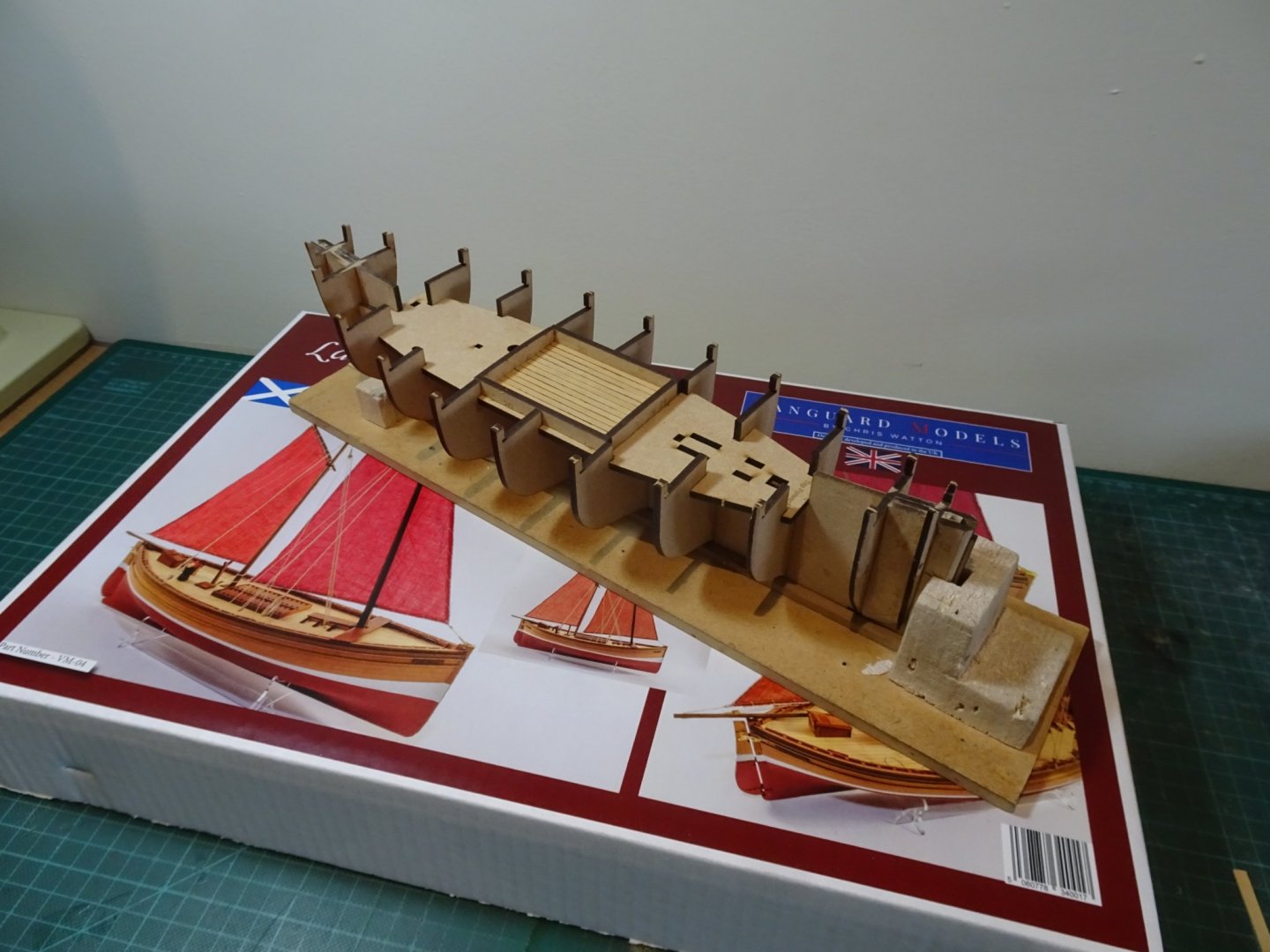
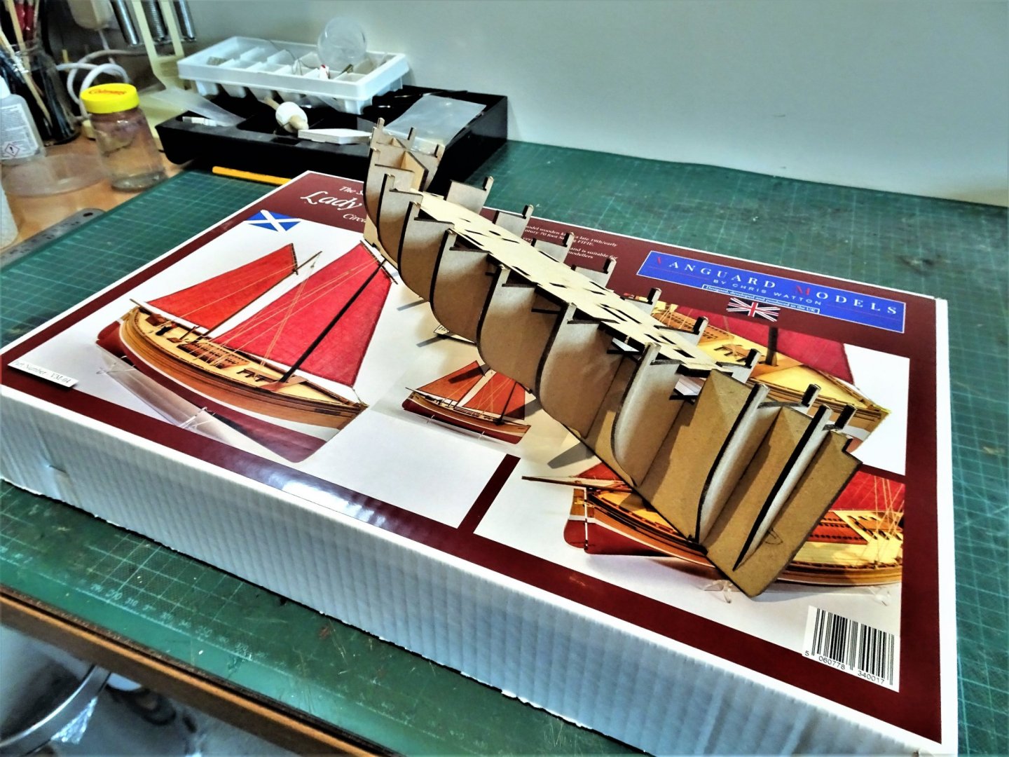
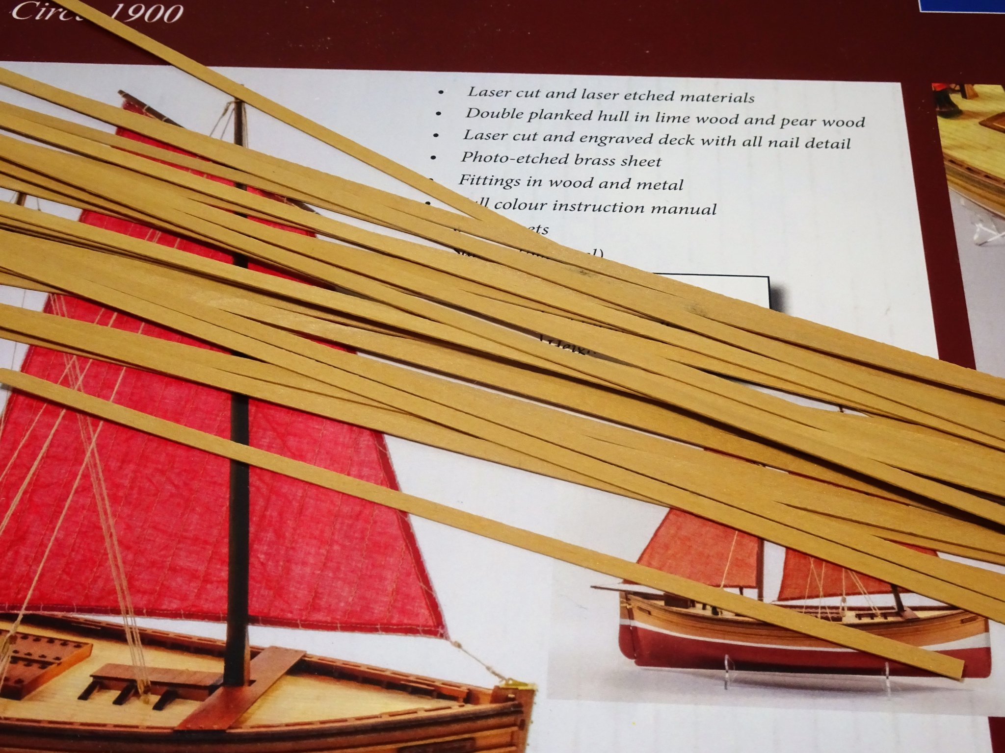
Building a Fifie Well Chris has done it again, he does have a knack of producing very appealing kits. When I saw Chris’s kit of this iconic Fishing vessel of North East Scotland, it seemed to meet a particular need I have at this moment. In the present covid 19 situation I have been feeling a little restless, a little unsettled, with a reluctance to commit to a more involved project such as my Royal Barge kit, as I had intended, following completion of the Alert Cutter build. The Fifie fits the bill. A model of moderate size that won’t require casing. Straightforward construction unlikely to present me with excess brain ache or worry. A relatively short build-time project. A project allowing me to research a vessel type I’ve little knowledge of and an excuse to buy more books – already arrived. and finally a change from the naval vessels I have been building over the past many years to date. I did wonder about doing a build log on the Fifie, given that James H has mostly detailed the kit both in his kit preview and build log. However, writing about a model as I build it is something I have got used to doing, and it will also fill in time during our current lockdown situation. The kit arrived today, securely packaged. First impressions are very good, a beautifully presented manual, and clear plans together with great materials. Two things that particularly caught my eye. The maple veneer laser cut deck, nice colour and layout; I doubt I will bother individually planking the deck on this one. The sail set; I’ve never been a fan of cloth provided sails on models invariably too thick and coarse. The sails provided with the Fifie (albeit at extra cost) are altogether different. The material is fine and soft, the stitching and bolt ropes beautifully done, and I’m pleased I invested in this ‘extra’ So to work, I don’t anticipate going ‘off piste’ too much with this build, but there may be little tweaks here and there as I proceed, and these I will mention as I go along, but it is likely to be a fairly short log. B.E. 12/05/2020
- 195 replies
-
- 17
-
-
- lady eleanor
- vanguard models
- (and 1 more)
-
The binnacle looks very nice, and would be a fine addition to the Pegasus kit, for those who prefer not to scratch one themselves. I'm not sure that style of binnacle would sit right on Alert, there is very little space between the tiller end and the skylight, and it would have to straddle or sit on the Bread Room grating/ cover. I thought about making a single chamber version, but decided against it. B.E.
-
As you've bought the grating set which has the cable cut out slots in the leading edge, you may wish to fill in the Navel holes cut into the deck. Navel holes were a feature of a later period. I think Chris removed them from the later issues of the laser deck. Otherwise you could simply place something over them such as a rope coil. B.E.
- 436 replies
-
- 5
-
-
- vanguard models
- alert
- (and 1 more)
-
I've never tried using poly over paint so I don't know. To bare wood it does bring up the colour very nicely and does impart a very subtle and slight sheen to the Woodwork. I suggest you try it on a bit of painted wood and see if you like the effect. Cheers, B.E.
- 436 replies
-
- 3
-
-
- vanguard models
- alert
- (and 1 more)
-
Personally I wouldn't use wipe on poly where I was going to paint. In my build I taped along the waterline level and applied poly above that up to the wale. I then taped above the waterline and painted below it. B.E.
- 436 replies
-
- 3
-
-
- vanguard models
- alert
- (and 1 more)
-
Cheers Chuck, I will have an order shortly🙂 B.E.
-
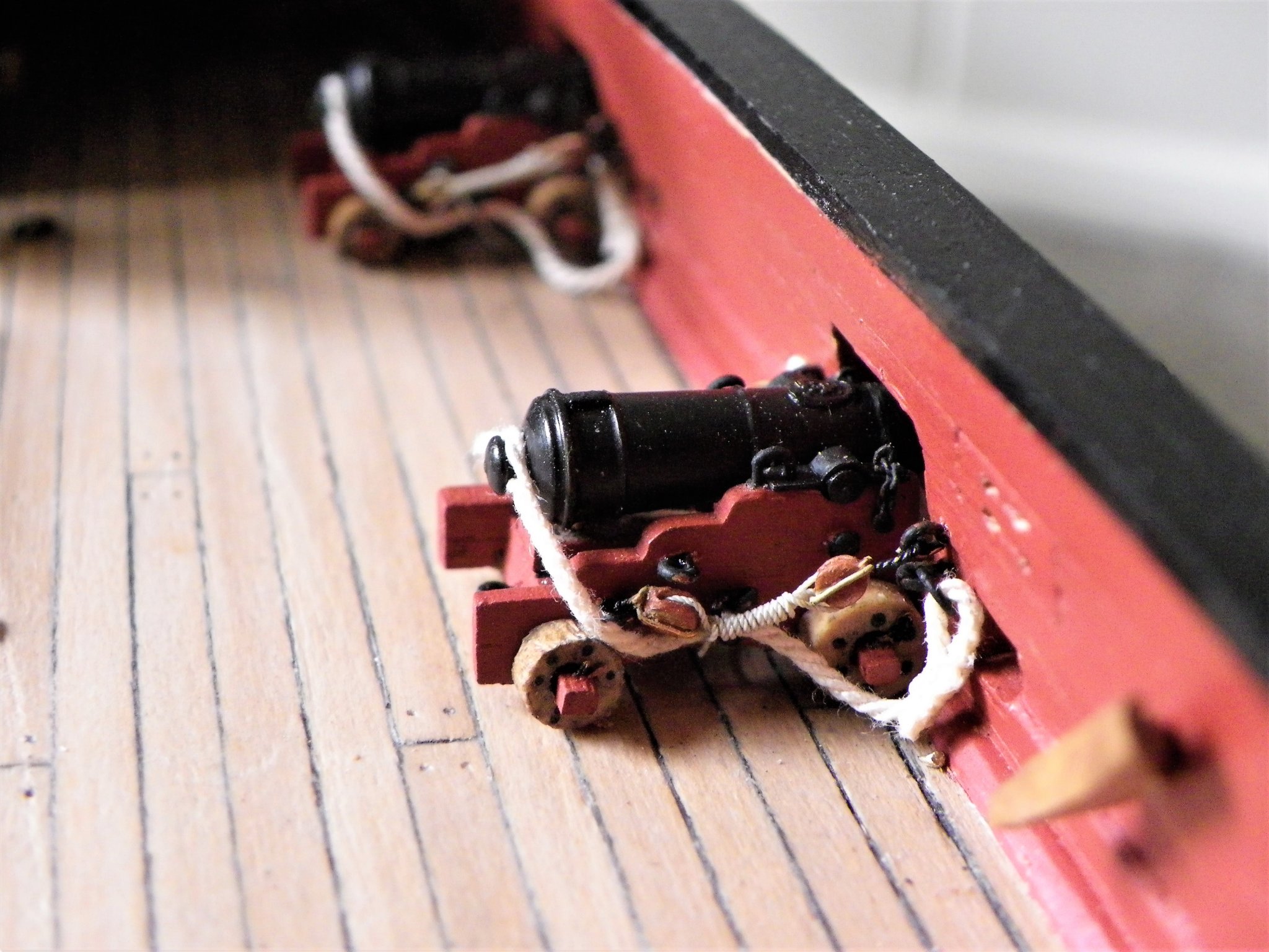
That would be great, thank you! I’ll enjoy it while I’m in our lock down. Stropping Small blocks My approach to block stropping differs depending on the block purpose, and of course the smaller the block the trickier it is. I am going to concentrate on the smallest of blocks used on gun tackles at scales of around 1:64. 4909(2) The now defunct 3mm plastic block set, I’ve only a few left. This is my approach to stropping a Syren Boxwood 3/32” (2.38mm) block using one of Chucks bijou 3mm plastic hooks. I am using Syren 0.20mm ø line. Blocks with hooks attached are the most fiddly, particularly in relation to the gun tackles, where overall length is critical and it is difficult to reproduce effective looking arrangements at scales of 1:64 and smaller. 4907(2) The block is held in a third hand tool, a smear of pva drawn across the strop grooves, and the line passed around the block and held until the pva grabs. 4908(2) I can then tie the ends with a simple square knot (In larger blocks I put a small seizing (0.1mm line) to secure the two ends of the line. 4912(2) One strand of the line which consists of three strands is then unravelled up to the point of the seizing. A spot of ca is then applied to this point and the strand is cut away, to allow fit thro’ the small eye on the hook of the remaining two. The ends are passed thro’ the eye of the hook from opposite sides. (I usually have to enlarge the hole slightly (and very carefully – these things are delicate.) 4918(2) The ends are then again tied above the eye, a spot of ca, and the ends trimmed away. 4921(2) For this exercise I use a new No 11 scalpel blade, nothing gets closer or cuts cleaner. 4922(2) The completed block and hook cover an overall length of only 6mm, which allows a reasonable lanyard length between the two blocks that make up a side tackle. 4925(2) The lanyard also of 0.2mm line is attached thro’ the top of the strop using a needle 4932(2) and secured with a false splice. 4933(2) I apply a smear of pva to the splice and roll between my fingers before trimming the short end. 4039(2) The tackles can then be made up on a little jig. 4177 At normal viewing distance these are very small but can be clearly seen as a tackle with two blocks and hooks, but which don’t overwhelm the scale, and well worth the fitting in my opinion. Prior to the advent of Chuck’s little hooks I also used an alternative method. This involves drilling a micro hole in the block and inserting a hook made from a fine eye bolt. 4939(2) I insert a drill bit into the sheave hole before ca’ing the hook to prevent it being blocked. At this size I dispense with any notion of making an eye on the hook, to save length. In the case of Alert the overall length of the combined block/hook should be no more than 6mm. 4940(2) The line is passed around the block as before. 4941(2) This time the line is passed around the stem of the hook and secured with a square knot. A spot of ca is applied to the knot and the ends cut off. 4943(2) The overall size is the same as with the little plastic hooks. An alternative method would be to insert the hook stem thro’ the line into the block and secure the strop at the other end. This would work where a lanyard was not required to be fitted. One other method which I used on my Pegasus build is good for smaller scales. Here I use thin wire to strop the blocks, forming the ends into hooks. 003 Wire stropped blocks on Pegasus. This method does entail painting the wire strop rope colour and the hook black, but it works just fine. So there it is for what it’s worth. Cheers, B.E.

.thumb.JPG.214783c890f935123b5ce6e13761fdbd.JPG)
.thumb.JPG.a5e927027da99f64846b70efc8e9fc59.JPG)
.thumb.JPG.c764564fd762a491b28ae90f4d4530fd.JPG)
.thumb.JPG.c5e31578bc6199a03d54b485b1b8cb41.JPG)
.thumb.JPG.d2468d05249803bc6be037e5e9da8228.JPG)
.thumb.JPG.ebf86b49c5cfc9c51d7812b2d6673f53.JPG)
.thumb.JPG.1b62eb6ba9088126db868221b73d3440.JPG)
.thumb.JPG.88a1b61908ffd1bb7236fe708e857346.JPG)
.thumb.JPG.a2bb654559b5fe2808122fb4dd7e2ebf.JPG)
.thumb.JPG.68aa915fc571b2f90e524cf9deff21df.JPG)
.thumb.JPG.90a4dbf9e0f906385c3042b2e37ce1ca.JPG)
.thumb.JPG.9ed772ce0d7f5672a59eb5832b4f6bbf.JPG)
.thumb.JPG.92e5be15fc7b91d7d3779b62dd4ebce5.JPG)
.thumb.JPG.f71a45af2a8d8fa28105ad14799549a0.JPG)
.thumb.JPG.8e68096a4ab5d3b5ee70475e1879b77d.JPG)
- 335 replies
-
- 11
-
-
- alert
- vanguard models
- (and 1 more)


.JPG.02eee804f235bc459310b9eae56551ea.JPG)
.JPG.77cc33ab4652b87ccf9e59c871906ffd.JPG)
.JPG.76ada1853f55b5e24bad3a255932497b.JPG)
.JPG.39ee96525796e1dcddc22b75cf9dc3de.JPG)
.JPG.836075f5b032ff050c7135202ad2e58a.JPG)
.JPG.56ea85a4dc7406bc2a11dec876dcad89.JPG)
.JPG.5dc9eb121b29bea79116d4ca05090598.JPG)
.JPG.7997740760b660d568fd4794138506c2.JPG)

.JPG.a94852a0b432d918394e47131ddd460d.JPG)


.JPG.623747d2f95d9e56e9cd284b69b849ee.JPG)
.JPG.f7bbe4f440174a6aacb867d9e8349894.JPG)

.JPG.d64c9aa566a9ecfae1c3fd9a0305ae3c.JPG)
.JPG.54e04a4e19e825eb142a02e3834df119.JPG)

.JPG.d243050ddae870c9824aa671c29608ad.JPG)
.JPG.d412c100b742b1e5276d6f99e8d6edce.JPG)
.JPG.06de6e781a738b169f4a71adcb3e1569.JPG)
.JPG.1a9828ef644080835cfb8d798a91896f.JPG)
.JPG.d6fdfc8a558b6b86f9a39ca7cf00c6bf.JPG)
.JPG.e7c73102dbefb272ac8c7a4b27489ff8.JPG)
.JPG.24695d9deabe54d077c21ee6bef859b8.JPG)
.JPG.8dcef4086d5249699fda630df5ceca5e.JPG)
.JPG.1feb7cb45450d7d2acf1261d6c046256.JPG)
.JPG.4c44741667cdc33686ad433376d5cd0e.JPG)
.JPG.062a0ca642412ae06f3de4dc4c506bbf.JPG)
.JPG.f42b004d47f91ee4b072a8e653d4eefb.JPG)
.JPG.bac3291350fcde42506aae668ad4fc84.JPG)
.JPG.52448efb03245d85fa0f09e4854cf499.JPG)