
HOLIDAY DONATION DRIVE - SUPPORT MSW - DO YOUR PART TO KEEP THIS GREAT FORUM GOING!
×
.JPG.ca33079f5815b861e67b9c2cccd37982.JPG)

Blue Ensign
-
Posts
4,564 -
Joined
-
Last visited
Content Type
Profiles
Forums
Gallery
Events
Everything posted by Blue Ensign
-
 Your Speedy is looking beautiful Derek. On the subject of side tackles I don't think the difference between four and six pounders is that great in terms of fitting difficulty, and in my opinion is feasible at 1:64 scale. 2mm blocks are the size to use along with 0.1mm line. Hooks are the big issue as provided brass etched versions are out of scale and take up too much room. A simplified approach is to use thin wire or modified small eyebolts to make hooks which don't detract from the look at the scale involved. Making up 28 tackles is a bit of a pain, but the job can be done at intervals and setting up a little jig helps a lot. B.E.
- 725 replies
-
- 1
-

-
- vanguard models
- speedy
- (and 1 more)
-
No time like the present, I have re-aligned the water-line at midships. 5557 5541 5540 5559 I think I will leave it alone now until I get the paint for the Boot topping. B.E. 16/06/20
.thumb.JPG.f57ab6759bc964fcb309cfc722d7c573.JPG)
.thumb.JPG.f8462d7f878bb8efd2b77d7b66afdc17.JPG)
.thumb.JPG.804054be0302b3a39b2fd7407a441678.JPG)
.thumb.JPG.e2c49815e825abea9e94050d563f3da9.JPG)
- 195 replies
-
- 15
-
-
- lady eleanor
- vanguard models
- (and 1 more)
-
Cheers James, I was thinking that, the bow and stern points are as per plan, I'll have another play with it. 👍 B.E.
- 195 replies
-
- 3
-
-
- lady eleanor
- vanguard models
- (and 1 more)
-
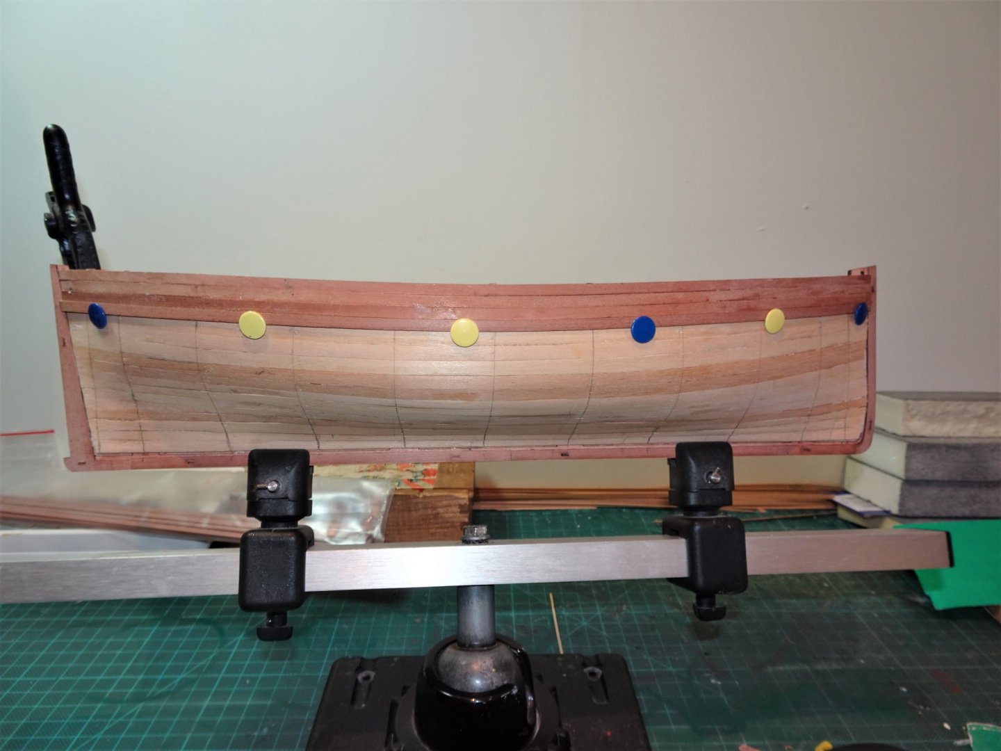
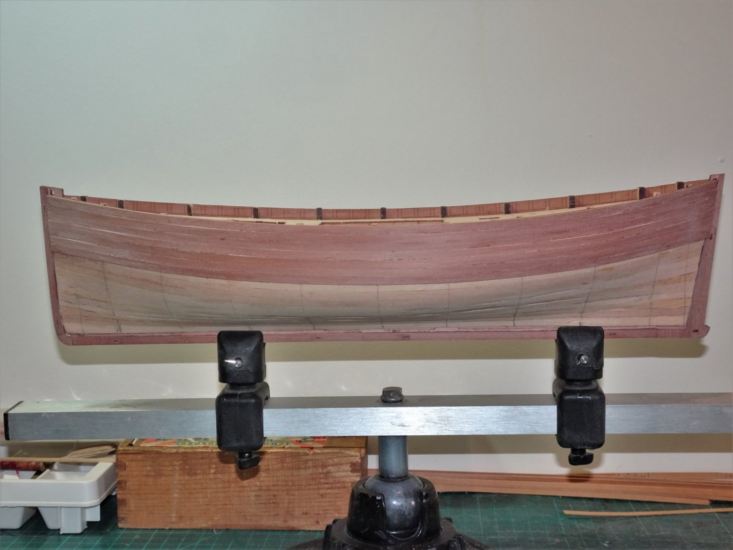
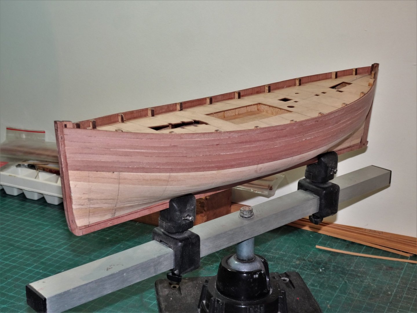
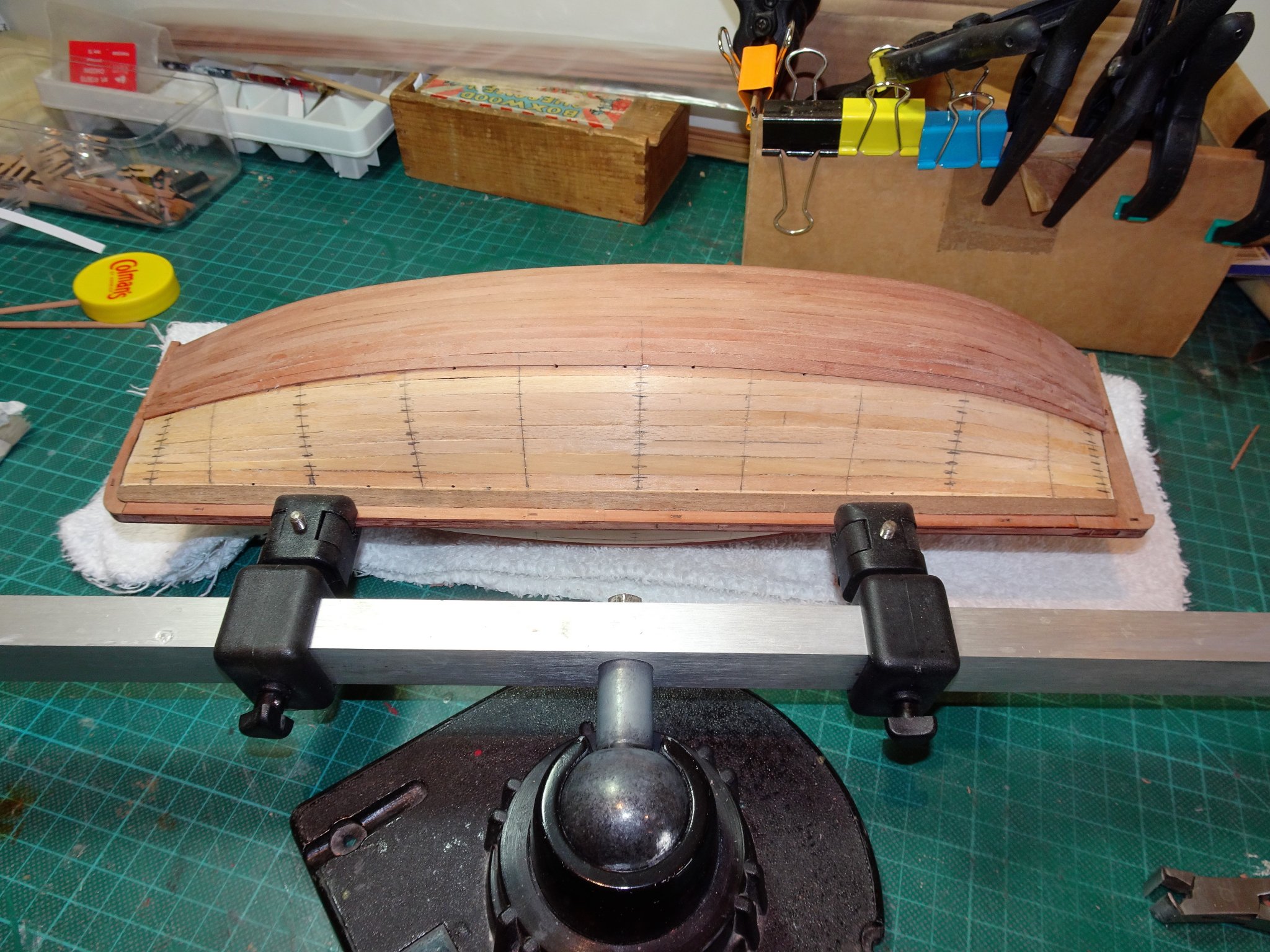
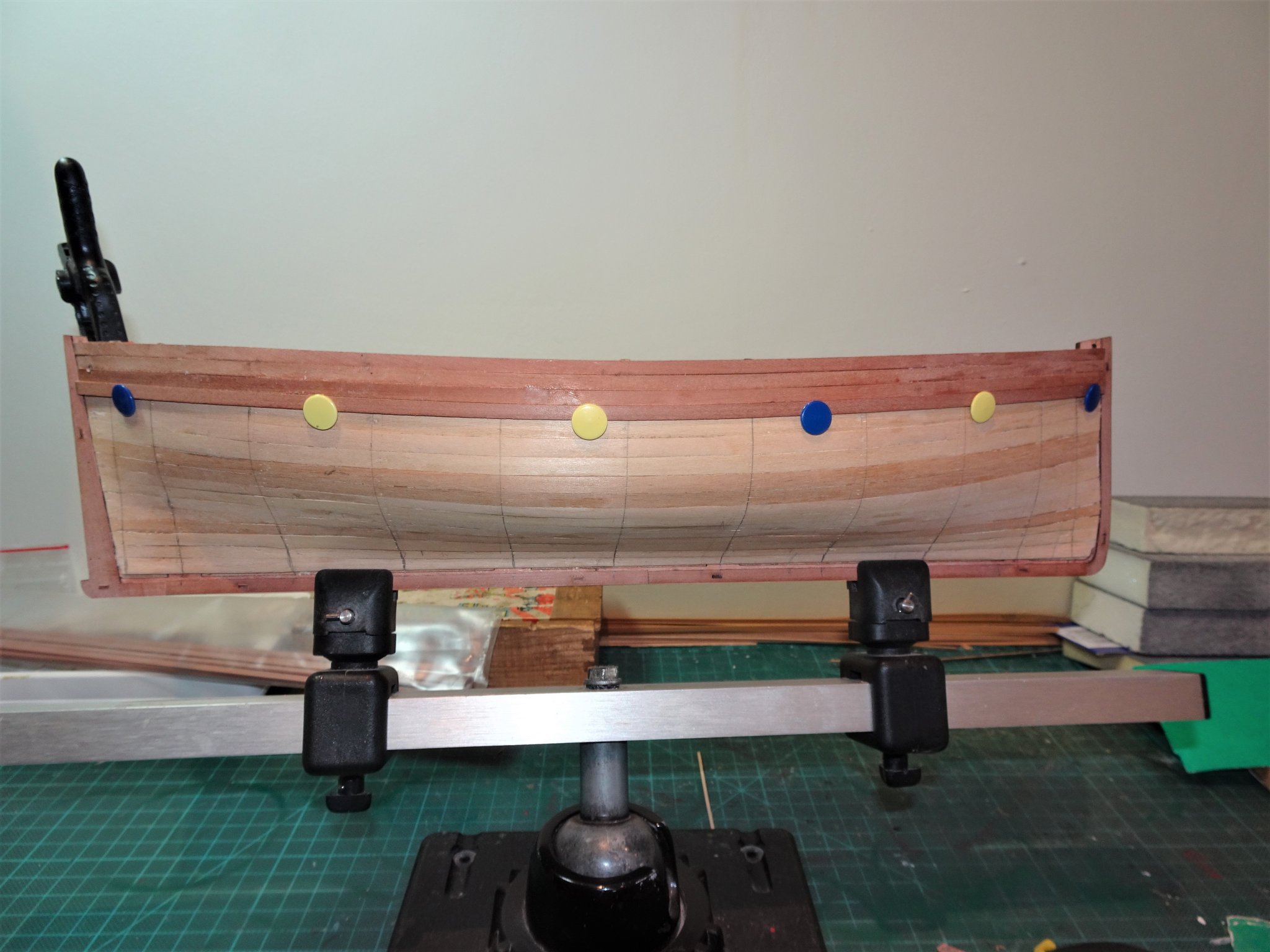
Post 12 That Waterline business I admit I hate doing waterlines, but I thought with this fairly simple hull form it would be ok. It wasn’t. Neither was it clear where in the cradle the hull was supposed to fit. The hull was a good but not a perfect fit and there was a choice of positions which suited, one as good as another. Was there any hull drag involved? The plan seems to show the top line at the bow below the top point at the stern, which would suggest drag. I first tried the (common) method of marking the bow and stern points by measuring down from the stem and stern posts, and then used the Amati waterline marker along the hull. James made it look easy, but for me this didn’t seem to produce a good result. The bow and stern point were fine but the line seemed to go far too high up in centre area of the hull at mid-ships. Conversely if I start at the centre the bow and stern points are too low. My next approach was to use the bow and stern points and measure down from mid-ships on the plan and mark this on the hull. Tamiya tape was then run smoothly between the three points. This resulted in a lower centre line which looked better to my eye. 5510 Nothing for it but to run the test and apply a base coat of paint, and see how it met the eye. 5515 I prefer to hand paint wooden models, gives a more natural look to my eye, but each to their own. 5516 5519 I have used Vallejo Flat Red for this first coat, it looks brighter under the flash than it really is. I do have some Hull Red on order, which is of a darker tone 5521 5528 5529 5532 5535 This is as far as I will go for present, I’m not quite sure whether the mid-ships line needs to come up a tad, so there may well be some fiddling yet to do. B.E. 16/06/20
.thumb.JPG.14d2fef44f8b117e13145c20cc8de3ce.JPG)
.thumb.JPG.ad08e3163dfcbb645d378bb6531b2afd.JPG)
.thumb.JPG.b9cf086394f18b7f8b471ba27a570d11.JPG)
.thumb.JPG.d43a87aefb95f58c3d7779d352b63b63.JPG)
.thumb.JPG.60633699a18a2ab25e45e10e41470f3e.JPG)
.thumb.JPG.206b5e1014c94f5cce0fcf91a8455605.JPG)
.thumb.JPG.8de983ae224eecebe96f89e92f586628.JPG)
.thumb.JPG.31ab887cf9983cb944ecaf7ee68c7e0d.JPG)
.thumb.JPG.b52b1bdb2b344bed0a20a1202b5ef0a8.JPG)
- 195 replies
-
- 14
-
-
- lady eleanor
- vanguard models
- (and 1 more)
-
Thanks, Rusty, Derek, and Bob. @ Derek - thanks for the heads up, I'll look it out. @ Bob - I had a senior moment there, I meant to say Acetone to clean ca, I have amended my post to avoid confusion. For the non waterproof pva I generally use water. Cheers, B.E.
- 195 replies
-
- 1
-
-
- lady eleanor
- vanguard models
- (and 1 more)
-
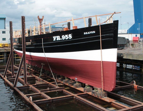
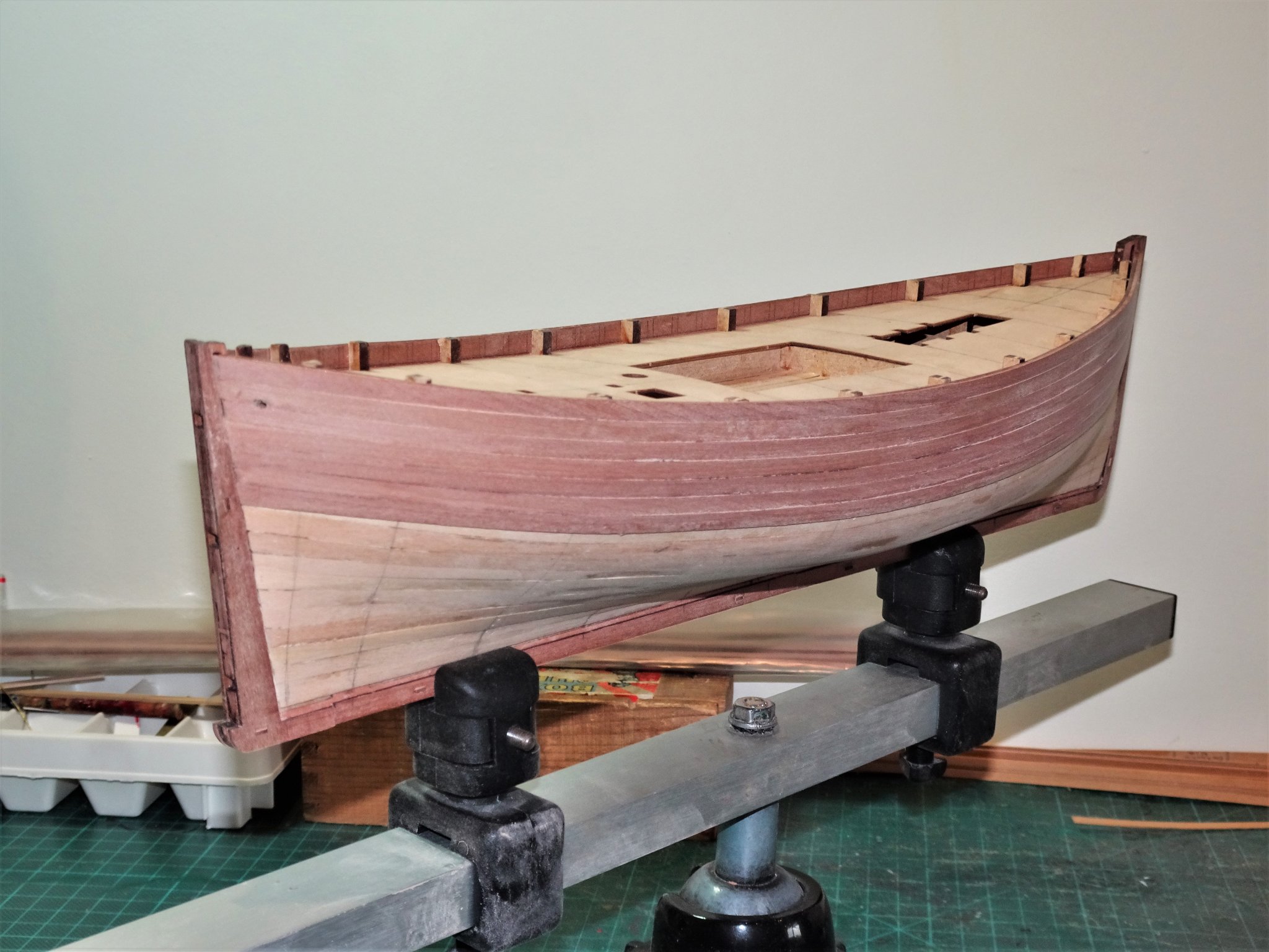
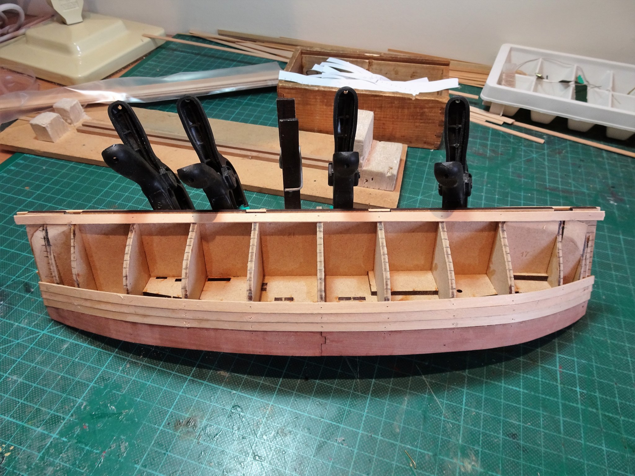
Post 11 Progressing the hull At this point I add the bulwark rubbing strakes comprising half-round Walnut strip. Nice quality strip that does the job perfectly. I think this will make a nice contrast to the Pearwood planking. I found using pva adequate for the purpose rather than ca. Below are two other rubbing strips also of Walnut. The kit manual suggests that the first of these is positioned around 3mm below the upper strake, and the second 4mm below that. The name plate fits between these two strakes. I have looked at many photo’s of Fifie’s and similar boats and there doesn’t necessarily seem to be a set positioning, or even number of rubbing strakes along the sides. Reaper Looking at the Reaper these two lower rubbing strakes are below the name and Registration number. Swan. The same applied to the Swan. 5474(2) I have opted to place the first strip 6mm below the upper strake, and the second 4 mm below that. 5478(2) I used Tamiya tape to set the position. I found it tricky fixing these very narrow strips as ca is really the only option, and the risk of marking the surrounding areas with glue is high. I applied Acetone using a fine paint brush to clean up as I went along. 5481(2) 5483(2) 5488(2) Starting to look like a fishing boat now I think. 🙂 B.E. 15/06/20
.thumb.JPG.9864cf02e27129c500c7db53ff2f9b71.JPG)
.thumb.JPG.902c53296d18c0f9d83e55c59f3be42c.JPG)
.thumb.JPG.db792df594fd7655124f543078303908.JPG)
.thumb.JPG.61d16a33fea6fbeedcb4c5280d0a3e91.JPG)
.thumb.JPG.a33abef9e0796e02c04a2f32260c4593.JPG)

- 195 replies
-
- 14
-
-
- lady eleanor
- vanguard models
- (and 1 more)
-
Nice work Bob, 👍 I’m glad I didn’t have to cut into that loose grained king plank, but you’ve made a fine job of it to produce a striking deck. Regards, B.E.
-
Thank you Bob, I’ve never built a model where planks have been joggled into a central king plank, but different rules may apply to yachts. I usually start either side of the central line, and only start joggling where without it the plank ends would come to a point or less than half the full width of the plank. I select the scale plank widths between six and eight inches, 3mm width planks suit my eye at 1:64 scale. I don’t tend to pre-determine where joggles are likely to end, my main consideration in planking is getting the butt shift pattern looking acceptable, and fairly matching each side. For the caulking I use a chisel point waterproof marker run along one edge only of the plank. I’m off to have a look at your Pen Duick now, and the intriguing planking arrangement. 😉 B.E.
- 195 replies
-
- 3
-
-
- lady eleanor
- vanguard models
- (and 1 more)
-
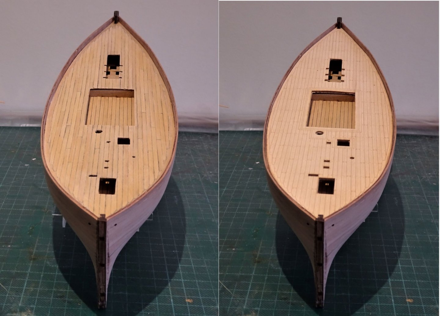
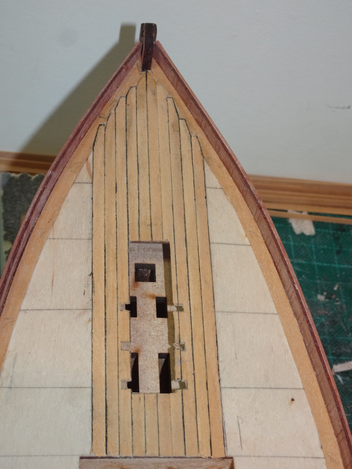
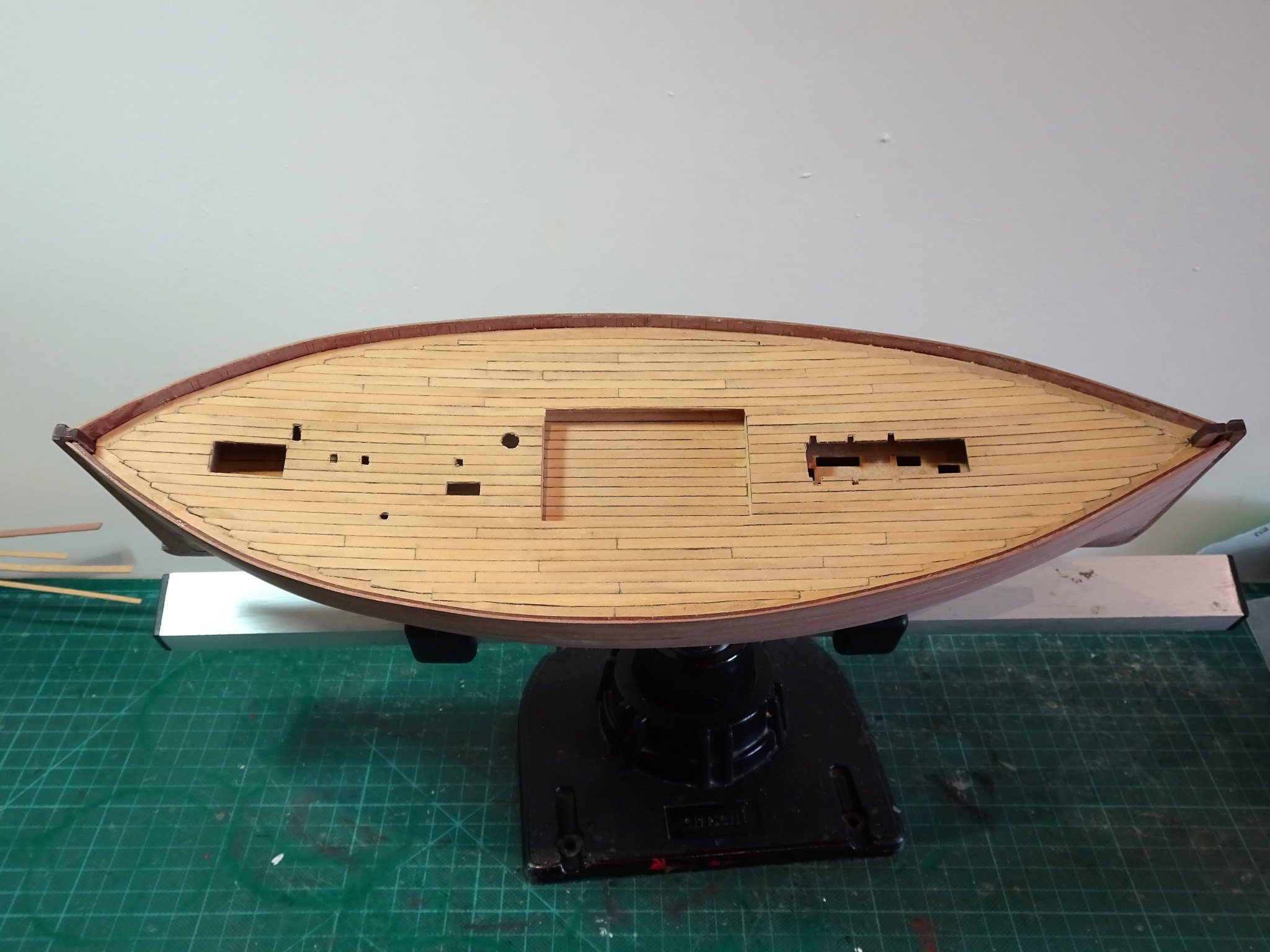
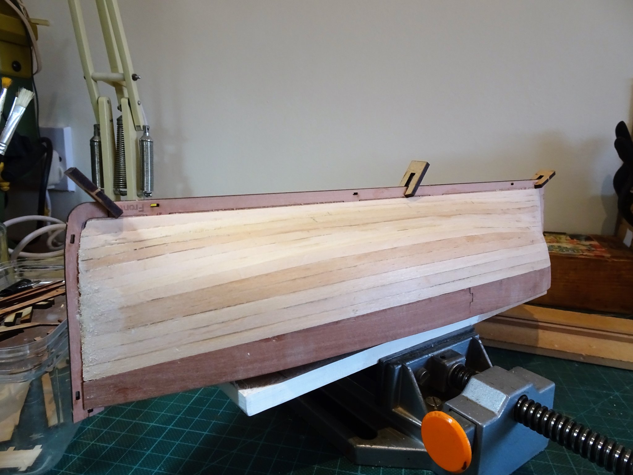
Post 10 Deck planking I will use 0.7mm thick Boxwood strip; 4.5mm wide for the margin planks, and 3.4mm for the planking, which are a good match for the etched scale planks. The first task is to fit the margin planks. Thanks to the fairly gentle curves this is done with edge bending a single strip. I start the deck planking along each side of the centre line. The overall scale length for planks within the area between the fish hatch boundary are within feasible full-length planks without the need for butt joints. This doesn’t mean there couldn’t be if the opportunity to use a shorter length presented itself for the purposes of economy of use. 5447 There is a need for joggling into the margin plank from the outset. 5450(2) Once I am outside of the fish hatch area I’ll work out a butt joint pattern. 5452(2) Completion takes a couple of days, the butt shifts are far less in number than on the etched version. It is a slightly less formal arrangement than on naval ships but the principles relating to adjacent butts and shifts has been followed. combo A side by side comparison. The laid deck requires scraping, but overall I prefer the look, and it didn’t take much effort to do it. Having the thin strip is necessary but the whole thing was done using Swann-morten micro chisels, and a No11 scalpel blade. I have dispensed with the mitred patterns surrounding the hatches etc as they are something I don’t recognise and can’t see the purpose of. 5463 The etched deck was useful as a template for cutting cleanly around all the hatch openings etc; 5471 I will now return to cleaning the hull in preparation for painting. B.E. 14/06/20

.thumb.JPG.42fcb275455d045af34719bc6c1030d0.JPG)
.thumb.JPG.3528a4cb725ebdd55a9017415ef6e9de.JPG)

- 195 replies
-
- 19
-
-
- lady eleanor
- vanguard models
- (and 1 more)
-
Hi Richard, I used a good quality pva for the first planking, and pins and clamps to hold it in place. I found that only a short time was required between the laying of strakes, but I then left it overnight before removing the pins. A different method is required for the second planking, and I found drawing pins in-between the bulkheads worked well for me. Hi Bob, I use a needle point to run the pva along the gap and then sprinkle the dust over it, blow the excess away, and run my finger along the line. The main thing to ensure is that any of the pva/dust combo is not left on the plank surface. The gaps I am using this method on are really only hairline, so the need to re-define the plank edges doesn't really arise. The method you suggest where the plank line was lost, is what I would do also, but I might consider re-doing the plank if that was the case. Thanks Guys, B.E.
- 195 replies
-
- 5
-
-
- lady eleanor
- vanguard models
- (and 1 more)
-
Remember the planking is clinker laid. They are not treenails, but representations of copper bolts and roves that secured the planking. You can see treenails which are the much smaller heads in-between the bolts. B.E.
-
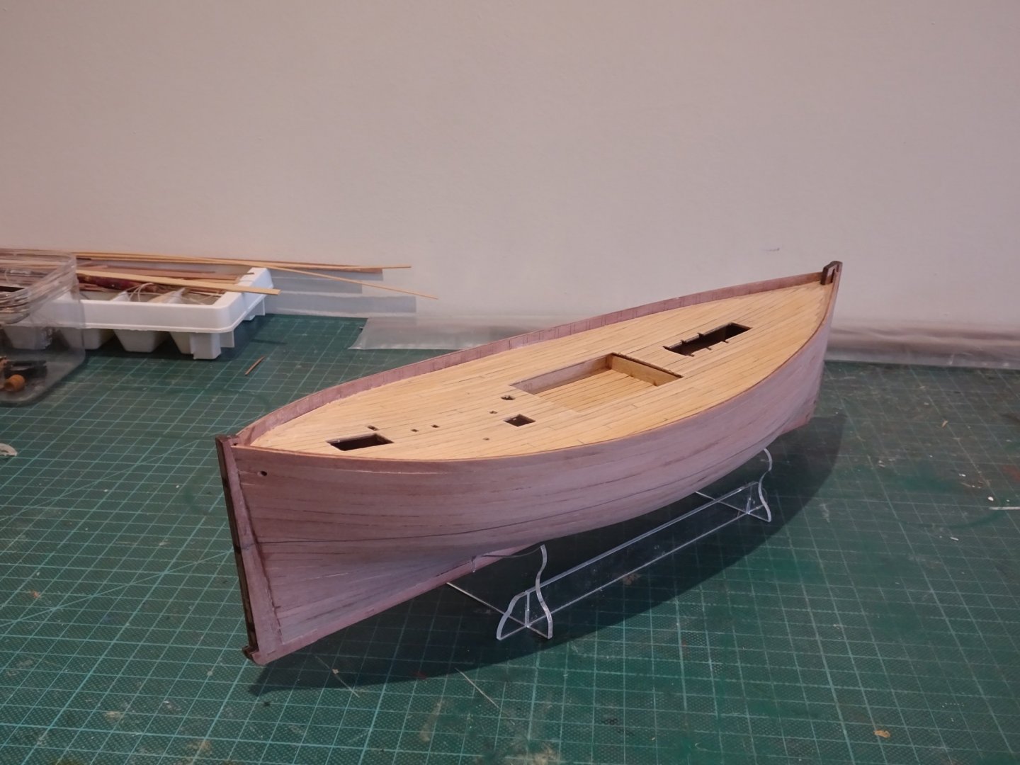
Post Nine Smoothing the hull and a decision to be made. 5422(2) The sanding of the hull continues and may take a while yet. A tip to those new to this game is to retain the Pearwood dust from sanding to use as a filler. 5411(2) Running pva along any minor gaps and brushing the dust over it makes for a colour co-ordinated filler. With the bulkhead tabs removed I can now try the provided etched deck on the model. I have to say it is a perfect fit, requiring no adjustment, well done Chris. 5413(2) This is my first opportunity with it in place on the boat to assess if I like the look. 5417(2) It would save me a lot of time, but I still have reservations about the perfect look of the deck, and I’m not sure I am that keen on the colour. 5420(2) I did trial various finishes on the scrap fish hold centre, wipe-on-poly, flat matt water-based varnish, and satin antique pine water-based varnish. 5418(2) Decision made. It is a small deck, and I think I can make it look more realistic. It may not be as clean as the etched version but perhaps more in-keeping with the vessel type. B.E. 11/06/20
.thumb.JPG.6762af743c6fc7cf657505ab74772c53.JPG)
.thumb.JPG.a9fbaeb7de70077d1e84bd34d3339703.JPG)
.thumb.JPG.825a14cba6c5a1af80110bb58b415893.JPG)
.thumb.JPG.2fb2d6185e11cf9a839a737b126a6014.JPG)
.thumb.JPG.8062f2326a1f4c26fbfe20d7e53c22f1.JPG)
.thumb.JPG.41e45f8289dbcfb94d59110f5604575f.JPG)
- 195 replies
-
- 21
-
-
- lady eleanor
- vanguard models
- (and 1 more)
-
Thanks Bob, I use a thick non- runny viscosity ca with a bond time of 10-20 seconds. The advantage is it doesn't drip or soak into the wood. It help a great deal to take the tension out of any plank which includes edge bending and twisting at times. A good quality pva will grab in under five minutes and is much kinder on the breathing but it still sucks the moisture out of your skin, which often leaves me with cracked dry fingers. Cheers, B.E.
- 195 replies
-
- 4
-
-
- lady eleanor
- vanguard models
- (and 1 more)
-
I have the Greenhill book, and MS118, and Scottish Fishing vessels by James Pottinger. Thanks for the link to the log by Kees de Mol, a very nice build, and one where strict three shift butt patterns are not in evidence. 😉 Thanks for for your help Tony, B.E.
- 195 replies
-
- 2
-
-
- lady eleanor
- vanguard models
- (and 1 more)
-
Thanks Tony, that is a useful reference. It is a constant frustration for us modellers that these detail items are so difficult to find, even less so with humble commercial boats, and I know very little about fishing boats at present. There are other things buzzing around my head such as the working of the rudder and connection to the wheel, I have e-mailed the Reaper museum in Scotland asking if they have any info on this. I am still wobbling over whether to plank her myself or save myself the trouble and use the etched deck, but the older I get, the less decisive I seem to get.🙄 Regards, B.E.
- 195 replies
-
- 6
-
-
- lady eleanor
- vanguard models
- (and 1 more)
-
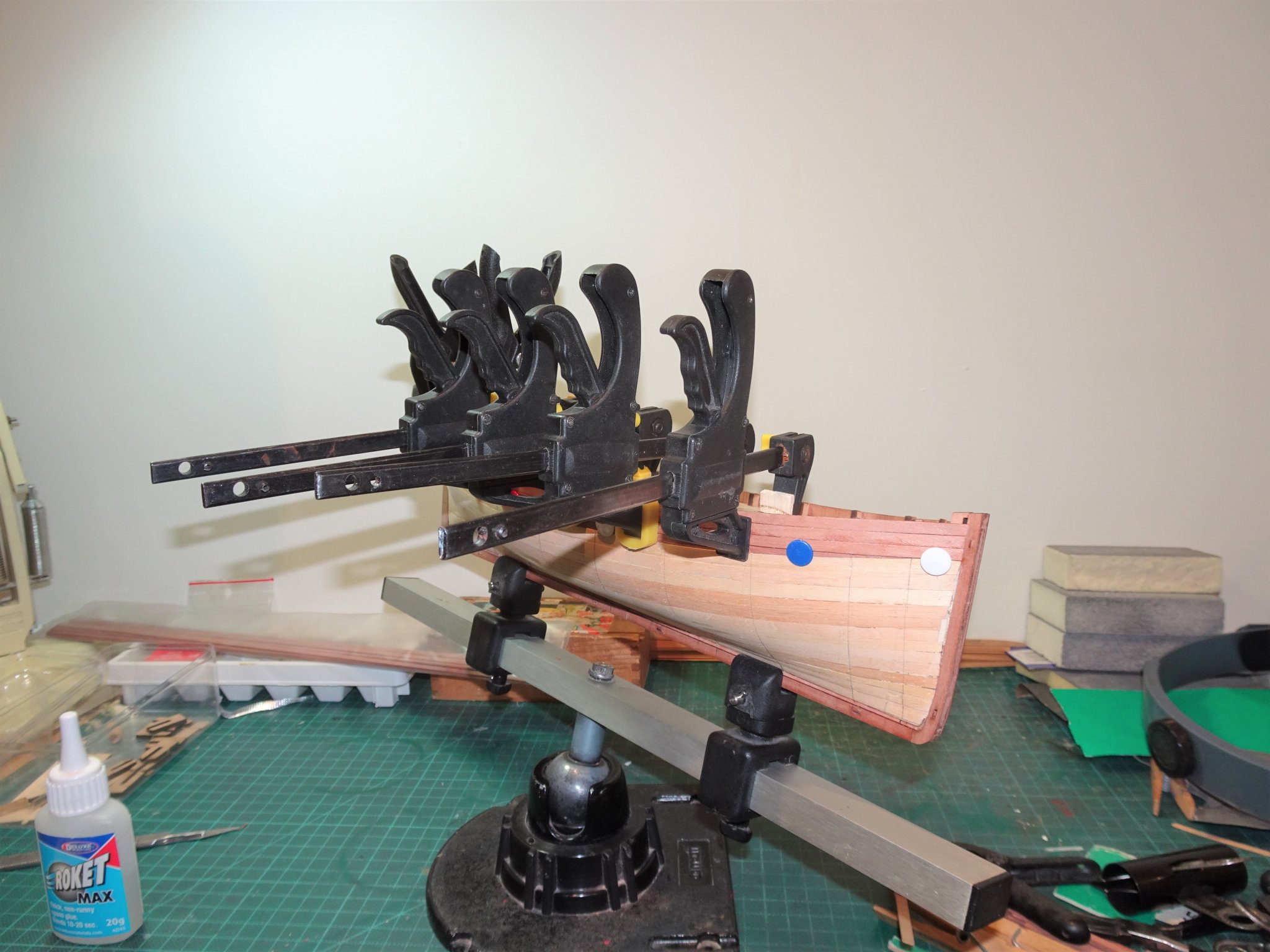
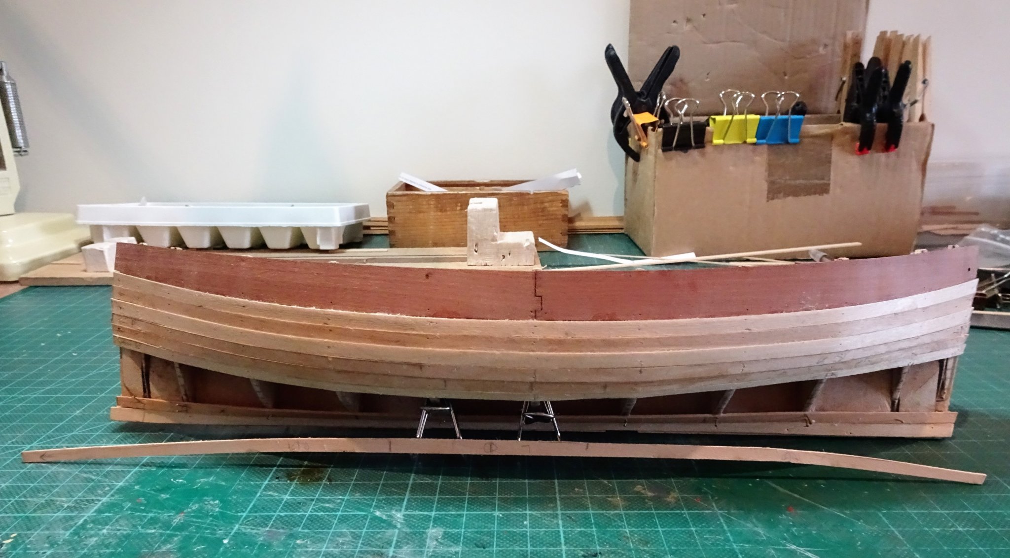
Post Eight Fitting the Garboard and working out the plank runs. I decided to fit a wider Garboard plank, and used a 5mm Walnut strip for the purpose, as this area will be painted. With the Garboard strake in place I can work out the remaining plank requirements. There are thirteen strakes left to complete. 5375(2) Each will require individual tapering and edge bending to suit. I am using a combination of ca for the plank ends at stem and stern, and pva in-between. 5376(1) I used the tick strip method to guide the runs marking the centre bulkhead (6) and bulkheads 1,3, 9, and 11. I didn’t think it necessary to mark all the bulkhead divisions with this shape of hull. 5371 At this point I am ten strakes down from the bulwark and below the painted area. I do tend to partly clean up the hull as I progress, taking some of the roughness off the planks. Some of the strakes are fitted in two halves usually because I made a mess of the tapering or length, but this is not an issue. Had I been planking correctly butt joints would have been required. In practise I think it a little easier to fit the strakes in two halves, but the butt joints do need to be staggered down the hull. With five strakes to go I return to fit another strake above the Garboard, this also I have fitted without taper. 5402(2) To complete the hull planking I did need to install a final spiled plank which was worked to be on the underside of the hull. 5400(2) The final plank to fit. 5403 5406(2) 5407(2) Always pleased when this aspect is completed. Well not quite completed, there is a fair bit of cleaning up to do on the hull, scraping and sanding to get it ready for the next stage. B.E. 09/06/20

.thumb.JPG.86a49dd68f16826bceb8a644ab0d0e2d.JPG)
.thumb.JPG.031f5475547e1cf5846ad3c0ed84ea13.JPG)
.thumb.JPG.ebe13f7d39b633e835b1ef0ca4ad8684.JPG)
.thumb.JPG.6bfc70113ca3216d6b90dd848e3a0977.JPG)
.thumb.JPG.9d1a8afc78ed12c552d56ad0ce4c6749.JPG)
.thumb.JPG.7846ee53b78e59fb573bcd51bab68a58.JPG)
- 195 replies
-
- 22
-
-
- lady eleanor
- vanguard models
- (and 1 more)
-
Advice needed - model ship made by my Grandad
Blue Ensign replied to Stee F's topic in New member Introductions
A very nice looking model that I would certainly hold onto particularly given the family history. You are lucky in one respect; as she is schooner rigged, the model will take up far less space width ways, than if she had been square rigged. I think she would sit very well on a specifically made shelf. ps . Your Grandfather followed in a fine tradition, there's quite a few ship modellers based in Staffordshire, I'm one of them. 🙂 Regards, B.E. -
Post seven Second Planking Before I start planking, I draw the bulkhead positions down the hull so I can mark the tick strip positions once I’m past the first few strakes. I will be using the provided 1x4mm Pearwood strip, and apart from any other consideration, I think the colour is more appropriate for a humble fishing boat than my usual Boxwood. I have no worries about sufficiency of the provided strip, as I still have the supply I didn’t use on the Alert build. The Pearwood strip is of an even colour but there are some strips better than others. Each strip has a better side and I sorted them for use above and below the waterline, before starting. Sanding will sort out most of the issues but it makes sense to use the best for the unpainted areas. My approach is to cut the planks and then heat treat whilst dry fitting to take the tension out of the strip before gluing. The first two strakes down from the bulwark are easy to clamp in place whilst the glue sets, but thereafter things get more tricky. 5341(2) From the third strake down I am using plastic coated drawing pins to hold the strips in place after gluing. These press easily into the Limewood planking and the heads are large enough to cover most of the plank width, whilst the steel pin holds the plank up tight to the one above. 5344 Down to the fifth strake larger clamps secured in the deck recesses suffice to hold the planks in place, along with the pins. 5347 Below the fifth strake the drawing pins will be the only clamping aid plus the use of ca for quick grab. I do worry about getting ca on the Pearwood surface and have a handy bottle of Acetone to wipe down the wood surface immediately after gluing. Useful as it is, I don’t like using ca over extensive areas, and following a test on the sixth strake I found I could restrict it to the bow and stern areas, and use pva for the rest. In the manual Chris mentions that he was able to fit five strakes of planking without tapering. 5361 I found that seven strakes fitted without any need for tapering. 5369 Port bow 5367 Starboard stern. I need to keep checking which way around the boat is with this ‘whaler’ shape. The next stage will require tapering of planks, so I will fit the Garboard plank, and mark off the plank lines down the bulkhead positions using a tick strip. B.E. 04/06/20
.thumb.JPG.ca91154b53d0fdddbb484e15d2ab23a2.JPG)


- 195 replies
-
- 18
-
-
- lady eleanor
- vanguard models
- (and 1 more)
-
You’re welcome Richard, and thank you. 🙂 B. E.
-
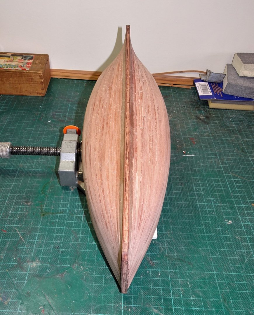
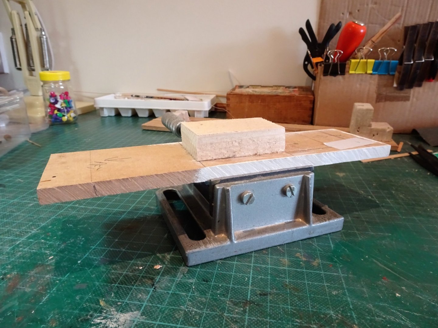
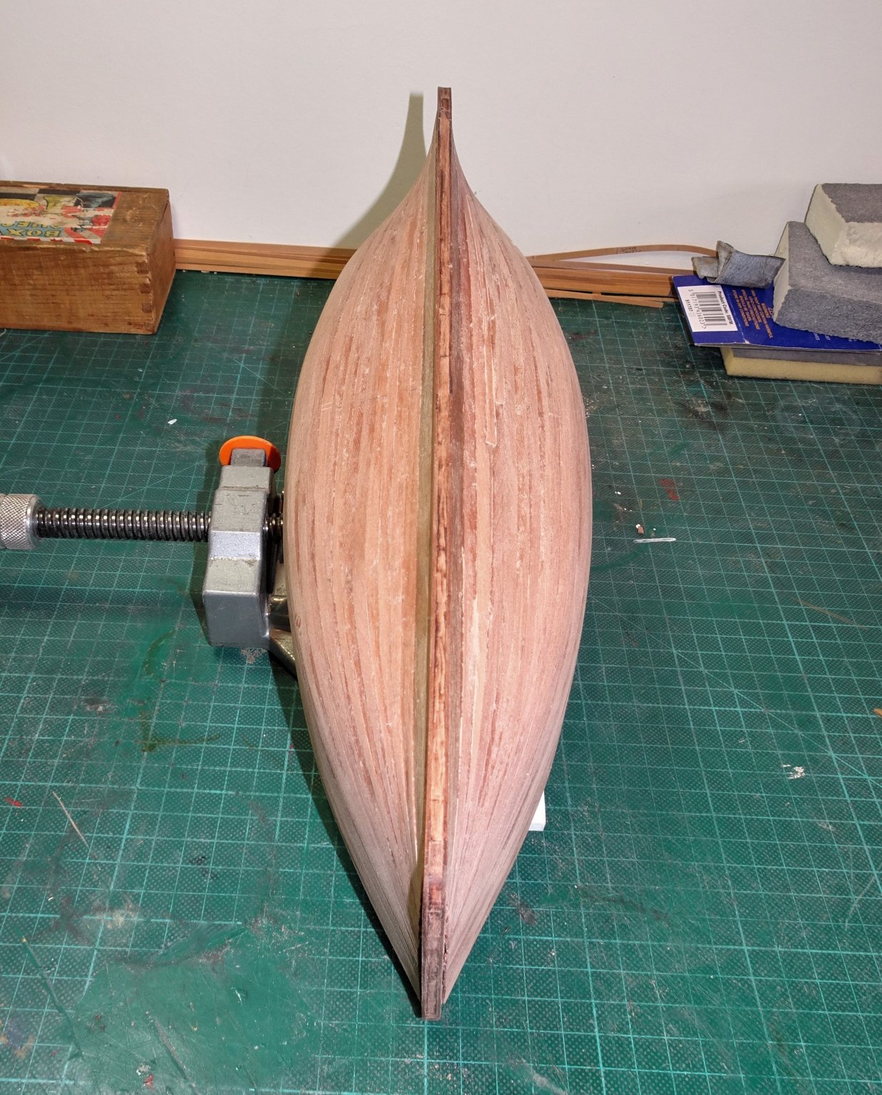
Thanks Bob, 👍 Post Six Completing the first stage Hull sanding is one of my least favourite jobs, but fortunately this one is not too onerous. I did pay particular attention to the line between the bulwark and first planking strake to ensure no ridge, and I use the blind feel test to seek out any irregularities. I finally use a thin flexible strip to run vertically down each station to detect any gaps or bumps. In total I used 24 of the provided Limewood strips, scrapped one, (wayward taper) and replaced two with wider strips. Stem, Stern post, and keel With the first planking completed, this is the next stage. 5315 The termination of my first planking leaves something to be desired, this was perhaps the worst example. A neat straight line as indicated in the manual photo’s on page 17 it ain’t. I found it quite tricky to trial fit the stem and sternpost parts and both snapped at the weak points where they connect at the top. Fortunately, it is an issue easily overcome. 5322(1) To straighten the planking line up I used the Pearwood rabbet patterns aligned to the stem and stern to mark the planking line which was then trimmed using a scalpel. The method Chris has devised is rather good. Small wooden pegs align the pieces perfectly, and the whole process is painless. Some minor filling was required to present a clean line, but there is a second bite at the cherry, as the second planking will hide it all. 5328 The keel pieces slotted into place without further issue, the provided clamps to hold the section in alignment are a nice touch. 5329 I made the simplest of jigs to hold the hull inverted, necessary once the second planking begins. 5327(2) The rectangular block simply slots into the fish hold to keep the hull secure. To complete this section the Pearwood rabbet strips are put into place, using the pegs provided to ensure alignment. Before gluing the Pearwood rabbet patterns there is a final opportunity to assess the rebate against which the second planking will terminate, and whether the first planking needs a final tweak to suit. 5335(2) 5337(2) 5333(2) After two weeks fairly leisurely work the hull is ready for the second planking. B.E. 31/05/2020
.thumb.JPG.76d2f97a01b29d0e3b93b7cb42a90d65.JPG)
.thumb.JPG.f626bd8af5e1dd31342a9dec06605690.JPG)
.thumb.JPG.9c1f1f47ab6cf51de654f5b54b49d778.JPG)

.thumb.JPG.54e7c56e4fdb68e256900515daf3f655.JPG)
.thumb.JPG.be02816083455f9291a9df0bf4410c62.JPG)
.thumb.JPG.fc100613562865c448dccbdab08023ab.JPG)
- 195 replies
-
- 19
-
-
- lady eleanor
- vanguard models
- (and 1 more)
-
Shaping up very nicely Eamonn, something very attractive about these schooner and cutter models. B.E.
- 1,039 replies
-
- 3
-
-
- ballahoo
- caldercraft
- (and 2 more)
-
Post 5 First planking A word about my approach to planking this hull. The proposed method of first planking works fairly well for a first layer as it will ultimately be covered up, but it won’t tell you anything about how to properly plank a hull, or produce the best result with the second planking. Planking should be relatively straightforward on this hull shape, and for the purposes of this first planking I took a partial tick strip and edge bending approach, which should result in a hull completed without the need to use stealers. I did mark off the plank widths at each bulkhead as a guide but effectively use only bulkheads 1 and 11 for the purposes of the taper. By using this approach I can see how the shape of the planks develop as I proceed which will be of benefit when I apply the more important Pearwood layer. This will be the first model I have built where the stem, stern, and keel are not in place, before I start planking which seems a little strange to me, but I’ll run with it. The Limewood planks do readily bend around this hull, but to take a little fight out of them I do soak before temporarily fitting, and applying hot air on max temp. They are then glue, pinned, and clamped. I fitted the first three planks without tapering, they followed the line of the bulwark with a gentle edge bend, and without recourse to water or heat. 5236 I then fitted the Garboard plank. This is a simple affair with a full plank run along the keel line, a benefit of the simple hull shape. No concerns about where to terminate or shape it at the bow end. The remaining space at midships (bulkhead 6) is 9 strakes of 5mm strip. As I work down the hull I paint the inside of the hull planking with slightly diluted pva, this strengthens the planking joins and helps reduce the risk of a sprung plank. This is only possible down to strake six as the gap is then too narrow. After the first three strakes the planks required tapering at both ends, as the hull is virtually the same shape at both stem and stern. These are quite long tapers. 5237(2) I found that a degree of edge bend, imparted by water/heat, was required from around bulkhead 8 towards the stern, but from midships to the stem the tapered plank followed the line with little resistance. 5281(2) With six strakes fitted from the top, I return to add a strake above the Garboard, and then return to planking from the top. The idea is that as I am using only single width planks, any remaining gap for the final plank that requires spiling will appear on the underside of the hull. 5284(2) When I came to plank 7 down from the bulwark, some edge bending both forward and aft was required. 5286 This is the shape required. The edge bend is downwards which appears counter intuitive when you look at the upward sweep of the planking. 5288 Nearing completion of the first planking. One of the drawbacks with kits is that they generally only supply one width of planking for the hull. In a properly planked hull there would be wider planks particularly for the Garboard, and for the plank runs towards the stern. 5292(2) With two strakes to go there is an annoying 2mm wide gap at midships, not entirely unexpected, and simply requires a wider board to suit. I fitted one more supplied strip, down from the top. 5294(2) This one needed the full treatment with tapering both ends, edge bending, and a twist at both ends to lie against the keel. leaving a slightly wider plank to complete. 5299 The final two planks will require to be spiled. 5302(2) I use Tamiya tape to give me a template to work to. In the absence of a wider limewood strip I cut the final spiled planks from some 1mm Boxwood sheet. It is then simply a matter of scrape and try, until the plank fits. 5313 First planking completed, it will now be sanded and scraped smooth, with hopefully minimal filler required. B.E. 29/05/2020

.thumb.JPG.1b4981f56134c43a4989775247f9b38e.JPG)
.thumb.JPG.0ae662847db353084fa8fee944a2acae.JPG)
.thumb.JPG.3daac78040550adeaae7ac2557ff5b4a.JPG)
.thumb.JPG.4b4e8b9680f7c26e099cf8fc168f9918.JPG)
.thumb.JPG.40d40da44451a65aee0222fd0e3a7e83.JPG)
.thumb.JPG.94a9cf4eb815ad75f0a60d6816526f83.JPG)
- 195 replies
-
- 23
-
-
- lady eleanor
- vanguard models
- (and 1 more)
-
You're doing a fine job on the decking, Derek, impressive joggling. 👍 B.E.
- 725 replies
-
- 3
-
-
- vanguard models
- speedy
- (and 1 more)
-
You could try asking your question in the general kit questions section, more appropriate than this kit specific build. B.E.
.JPG.5ad94bd1113eeddb666a8a5be739fc75.JPG)
.JPG.72f38c076281df17aaf7fe20e3bfb8ef.JPG)
.JPG.9d975be658ba2b2b9d9af17278955153.JPG)
.JPG.1d126302950860dcd78a065fac53ac83.JPG)
.JPG.f8a7a246cd71356b4966f005cbf2af8a.JPG)
.JPG.19d62d2de550fa206a6d35c7981298e1.JPG)
.JPG.95a7b64b2c12c1367d4c7f94e9cf7f14.JPG)
.JPG.12d98aa5af1708d5efdf8198bd38dfa7.JPG)
.JPG.3f923378ad238ca658bad26c3a1964d2.JPG)
.JPG.4483ad0d7e964779e737a9d1c4cf01f5.JPG)
.JPG.4716fbfab55f21a70432a61bbfde1b9f.JPG)
.JPG.ac5b0e251fbdf0c5d79288a0b1e38eb1.JPG)
.JPG.143336b88dedfae643386a09fd77211e.JPG)
.JPG.af3f1042e4251635c05520ecc82e9ac7.JPG)
.JPG.8be0b3000d1323c26ded8a3aeb399ef3.JPG)
.JPG.dc46fc3e0978db2c6fdd578991ce03ef.JPG)
.JPG.def54275c7a960179cca57a7aaf3f1e3.JPG)
.JPG.7f1d266bd52aea6d937d2e928d865bcd.JPG)

.JPG.7052a516ec79ae209af354dd8a9fcf90.JPG)
.JPG.e2a7709c9684ce429afccf7f8b34c72f.JPG)

.JPG.6bae178b2f74f163d8f198fb81887711.JPG)
.JPG.e1f55ee87b3b58860a5cc64612ca60ea.JPG)
.JPG.24d93cb3440ed158e82849b109157e0d.JPG)
.JPG.eeb0cc5d8c2564e862201fcc905ab1dc.JPG)
.JPG.b5223f5de30aa63317272f59203cde82.JPG)
.JPG.43f3a3a492a78446fe4d11bc8b29d508.JPG)
.JPG.945d1890be2eca0525f3385bde428edf.JPG)
.JPG.f9f6ab6001a84eb9f520fe392c54f03b.JPG)
.JPG.8ea6ca8f3d0de43d4d0950a98ef00cbd.JPG)
.JPG.d11f4ab6155ce2928d96728ba014feea.JPG)
.JPG.2863bea6b301f7ee68a9930ed5bd6248.JPG)
.JPG.2a11ee49d77b821aa893db450897886d.JPG)
.JPG.562a75d6421104f8836297ff4b490be8.JPG)


.JPG.4d62d7551bd58f518837e7d570fa5a92.JPG)
.JPG.00318dcc131e2add0811be5a64e61ea2.JPG)
.JPG.e34c10f73bfe60afdcce91ac1a803323.JPG)

.JPG.bf5348b6b9164e48d9a1fb6919a9dba7.JPG)
.JPG.b94be9d654659f814eb1f358d1ded32d.JPG)
.JPG.b50372357abf704ced530197b602ef5e.JPG)
.JPG.b26f005a496350ff898522fd505a932c.JPG)
.JPG.4d6d76ad410c077a4890d99a1ab4691b.JPG)
.JPG.a6828c29af6b8b2d9fea7da4f211301c.JPG)

.JPG.bc29e469fe52bba4a26045f2ebc9152d.JPG)
.JPG.6ec77cd286b5b3812524e4258effbfc3.JPG)

.JPG.b80a62b951a534dbac3210f3ec63ade3.JPG)
