.JPG.ca33079f5815b861e67b9c2cccd37982.JPG)

Blue Ensign
-
Posts
4,569 -
Joined
-
Last visited
Content Type
Profiles
Forums
Gallery
Events
Everything posted by Blue Ensign
-
 As you've bought the grating set which has the cable cut out slots in the leading edge, you may wish to fill in the Navel holes cut into the deck. Navel holes were a feature of a later period. I think Chris removed them from the later issues of the laser deck. Otherwise you could simply place something over them such as a rope coil. B.E.
- 436 replies
-
- 5
-

-
- vanguard models
- alert
- (and 1 more)
-
I've never tried using poly over paint so I don't know. To bare wood it does bring up the colour very nicely and does impart a very subtle and slight sheen to the Woodwork. I suggest you try it on a bit of painted wood and see if you like the effect. Cheers, B.E.
- 436 replies
-
- 3
-
-
- vanguard models
- alert
- (and 1 more)
-
Personally I wouldn't use wipe on poly where I was going to paint. In my build I taped along the waterline level and applied poly above that up to the wale. I then taped above the waterline and painted below it. B.E.
- 436 replies
-
- 3
-
-
- vanguard models
- alert
- (and 1 more)
-
Cheers Chuck, I will have an order shortly🙂 B.E.
-
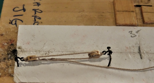
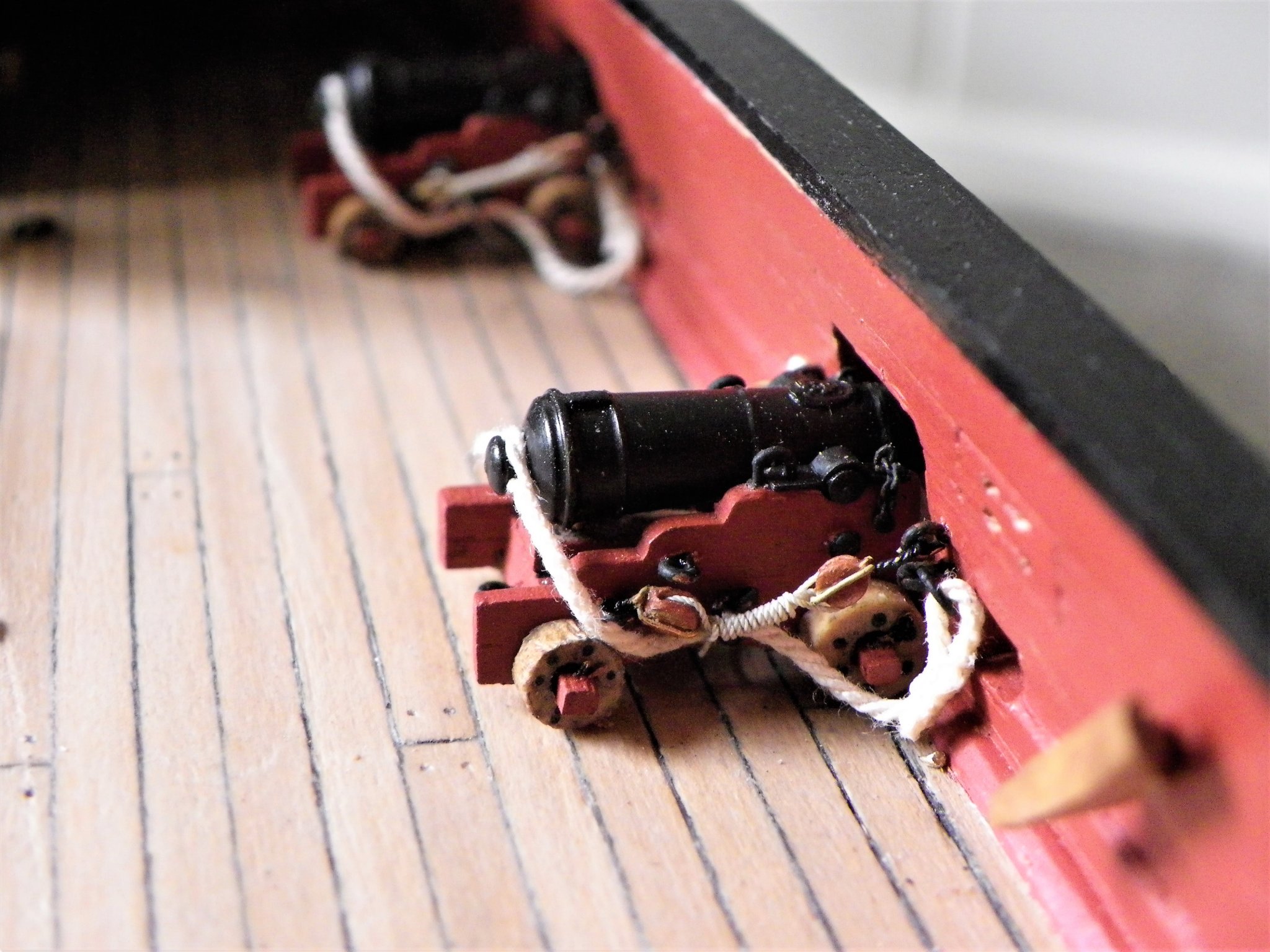
That would be great, thank you! I’ll enjoy it while I’m in our lock down. Stropping Small blocks My approach to block stropping differs depending on the block purpose, and of course the smaller the block the trickier it is. I am going to concentrate on the smallest of blocks used on gun tackles at scales of around 1:64. 4909(2) The now defunct 3mm plastic block set, I’ve only a few left. This is my approach to stropping a Syren Boxwood 3/32” (2.38mm) block using one of Chucks bijou 3mm plastic hooks. I am using Syren 0.20mm ø line. Blocks with hooks attached are the most fiddly, particularly in relation to the gun tackles, where overall length is critical and it is difficult to reproduce effective looking arrangements at scales of 1:64 and smaller. 4907(2) The block is held in a third hand tool, a smear of pva drawn across the strop grooves, and the line passed around the block and held until the pva grabs. 4908(2) I can then tie the ends with a simple square knot (In larger blocks I put a small seizing (0.1mm line) to secure the two ends of the line. 4912(2) One strand of the line which consists of three strands is then unravelled up to the point of the seizing. A spot of ca is then applied to this point and the strand is cut away, to allow fit thro’ the small eye on the hook of the remaining two. The ends are passed thro’ the eye of the hook from opposite sides. (I usually have to enlarge the hole slightly (and very carefully – these things are delicate.) 4918(2) The ends are then again tied above the eye, a spot of ca, and the ends trimmed away. 4921(2) For this exercise I use a new No 11 scalpel blade, nothing gets closer or cuts cleaner. 4922(2) The completed block and hook cover an overall length of only 6mm, which allows a reasonable lanyard length between the two blocks that make up a side tackle. 4925(2) The lanyard also of 0.2mm line is attached thro’ the top of the strop using a needle 4932(2) and secured with a false splice. 4933(2) I apply a smear of pva to the splice and roll between my fingers before trimming the short end. 4039(2) The tackles can then be made up on a little jig. 4177 At normal viewing distance these are very small but can be clearly seen as a tackle with two blocks and hooks, but which don’t overwhelm the scale, and well worth the fitting in my opinion. Prior to the advent of Chuck’s little hooks I also used an alternative method. This involves drilling a micro hole in the block and inserting a hook made from a fine eye bolt. 4939(2) I insert a drill bit into the sheave hole before ca’ing the hook to prevent it being blocked. At this size I dispense with any notion of making an eye on the hook, to save length. In the case of Alert the overall length of the combined block/hook should be no more than 6mm. 4940(2) The line is passed around the block as before. 4941(2) This time the line is passed around the stem of the hook and secured with a square knot. A spot of ca is applied to the knot and the ends cut off. 4943(2) The overall size is the same as with the little plastic hooks. An alternative method would be to insert the hook stem thro’ the line into the block and secure the strop at the other end. This would work where a lanyard was not required to be fitted. One other method which I used on my Pegasus build is good for smaller scales. Here I use thin wire to strop the blocks, forming the ends into hooks. 003 Wire stropped blocks on Pegasus. This method does entail painting the wire strop rope colour and the hook black, but it works just fine. So there it is for what it’s worth. Cheers, B.E.

.thumb.JPG.214783c890f935123b5ce6e13761fdbd.JPG)
.thumb.JPG.a5e927027da99f64846b70efc8e9fc59.JPG)
.thumb.JPG.c764564fd762a491b28ae90f4d4530fd.JPG)
.thumb.JPG.c5e31578bc6199a03d54b485b1b8cb41.JPG)
.thumb.JPG.d2468d05249803bc6be037e5e9da8228.JPG)
.thumb.JPG.ebf86b49c5cfc9c51d7812b2d6673f53.JPG)
.thumb.JPG.1b62eb6ba9088126db868221b73d3440.JPG)
.thumb.JPG.88a1b61908ffd1bb7236fe708e857346.JPG)
.thumb.JPG.a2bb654559b5fe2808122fb4dd7e2ebf.JPG)
.thumb.JPG.68aa915fc571b2f90e524cf9deff21df.JPG)
.thumb.JPG.90a4dbf9e0f906385c3042b2e37ce1ca.JPG)
.thumb.JPG.9ed772ce0d7f5672a59eb5832b4f6bbf.JPG)
.thumb.JPG.92e5be15fc7b91d7d3779b62dd4ebce5.JPG)
.thumb.JPG.f71a45af2a8d8fa28105ad14799549a0.JPG)
.thumb.JPG.8e68096a4ab5d3b5ee70475e1879b77d.JPG)
- 335 replies
-
- 11
-
-
- alert
- vanguard models
- (and 1 more)
-
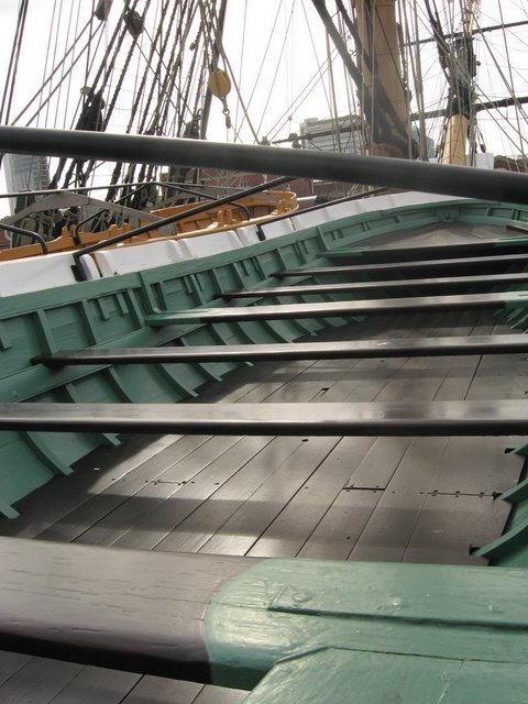
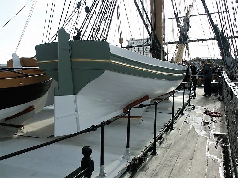
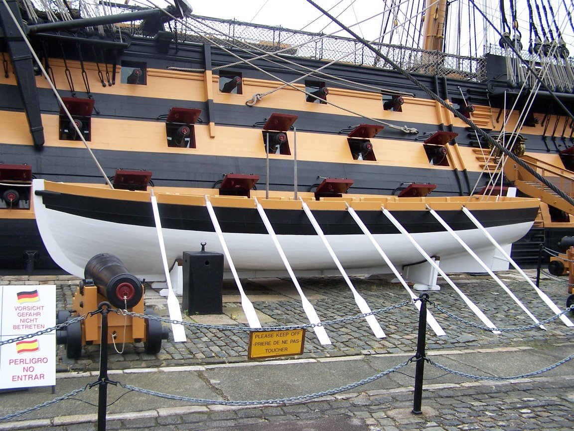
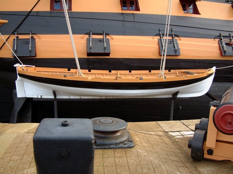
You could follow the scheme as presently on Victory ,or was the last time I was in Portsmouth The Barge has a green trim , I understand green was an expensive colour, so perhaps fitting for an Admirals Barge The Pinnace The Launch The Cutter I used the scheme on my Victory build, although I did trim the Pinnace Blue rather than black and yellow. B.E.
.jpg.86c866dda3d0bfc63d6d0a7b36a73300.jpg)
1.jpg.30b46afac10cca5672bce6ef5e33ff7f.jpg)
.thumb.JPG.3d0ea5811bb5dcefdfda3e9973b14860.JPG)
-
Thank you Phill, glad you found it of help. @ Chris, - Phew, it's always an added incentive when you have the designer of a kit looking at a build, I hope I've done your creation justice. @ Cap'n Hook - Thank s for looking in, much appreciated. B.E.
-
Hi Glenn, I can’t imagine that I can achieve anything as ‘pristine’ as Chuck but I do try to follow his example. 😃 As I'm virtually in lock down I'll knock up a little pictorial to explain my approach, something to keep me busy. Cheers, B.E.
- 335 replies
-
- 2
-
-
- alert
- vanguard models
- (and 1 more)
-
Your Pinnace looks beautiful Derek, and nicely photographed as well. Well done. B.E.
- 77 replies
-
- 1
-
-
- model shipways
- pinnace
- (and 1 more)
-
Thank you Joe and Glenn. @ Glenn, It's a pity Chuck stopped supplying those tiny 3mm black plastic hooks they were ideal for the gun tackle rigging on 1:64 scale guns. I also used them on my Cheerful build. Cheerful side tackles. Chuck also used to supply 3mm brass versions, but I didn't quite like those as much, and they had to be blackened. Brass etched rigging hooks were supplied in the Alert kit, nicely formed, but far too large for gun rigging, and in that situation my approach would be to fake it and form hooks out of very fine eyebolts glued into the ends of the blocks. After market brass etched hooks are supplied by the likes of Caldercraft, but again at 5mm they are too large. Perhaps we should petition Chuck to start supplying them again, I've never seen any quite as fine as those little plastic ones. Regards, B.E.
- 335 replies
-
- 5
-
-
- alert
- vanguard models
- (and 1 more)
-
Thank you Voyageur and Moab, glad you found it useful 🙂 Cheers, B.E.
- 335 replies
-
- 1
-
-
- alert
- vanguard models
- (and 1 more)
-
Thank you Grant, Derek, and Jason. At least with The Queen Anne barge I will have some excellent works to reference. 👍 B.E.
- 335 replies
-
- 1
-
-
- alert
- vanguard models
- (and 1 more)
-
Thank you guys for your great comments, much appreciated, I hope the log is of some use to those that follow. As for the future, uncertain as it seems at present, I do have Chuck's wonderful Queen Anne Barge beneath my bench, it may well be making an appearance. 🙂 Regards, B.E.
- 335 replies
-
- 12
-
-
- alert
- vanguard models
- (and 1 more)
-
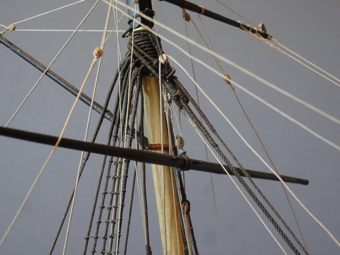
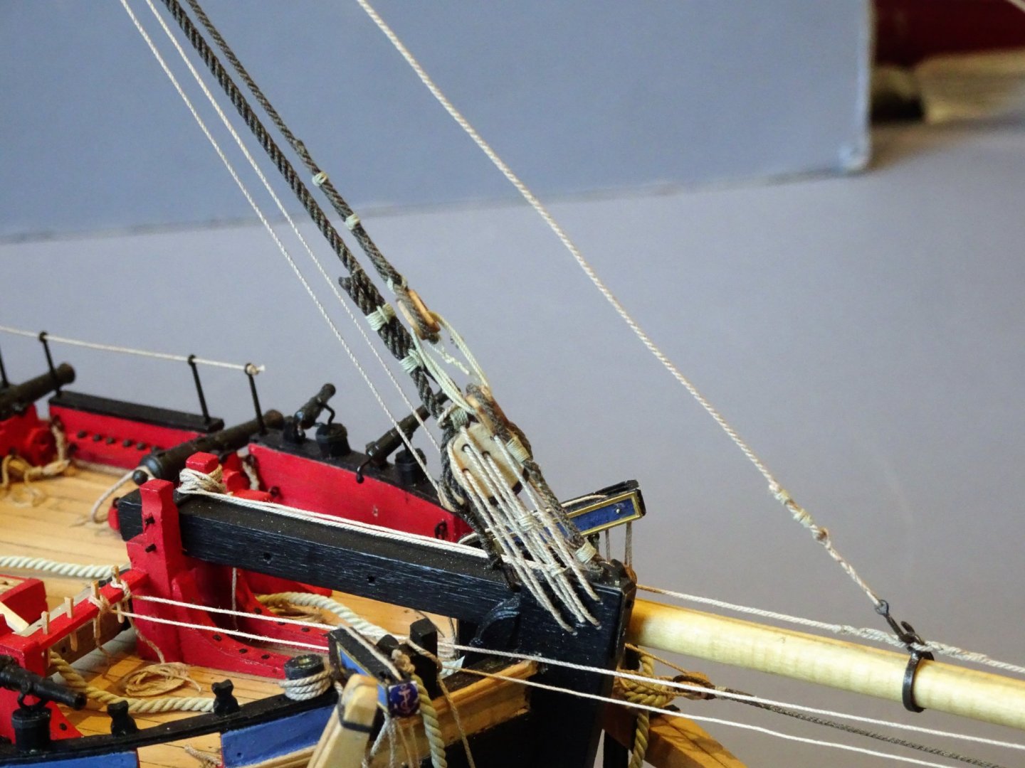
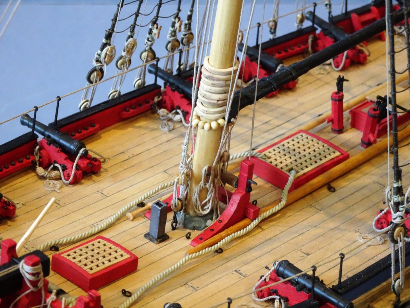
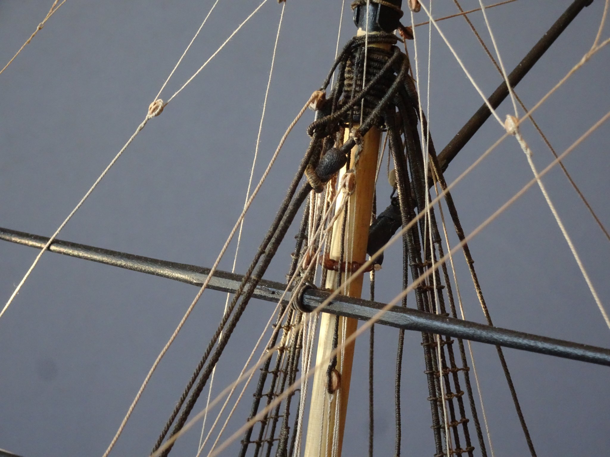
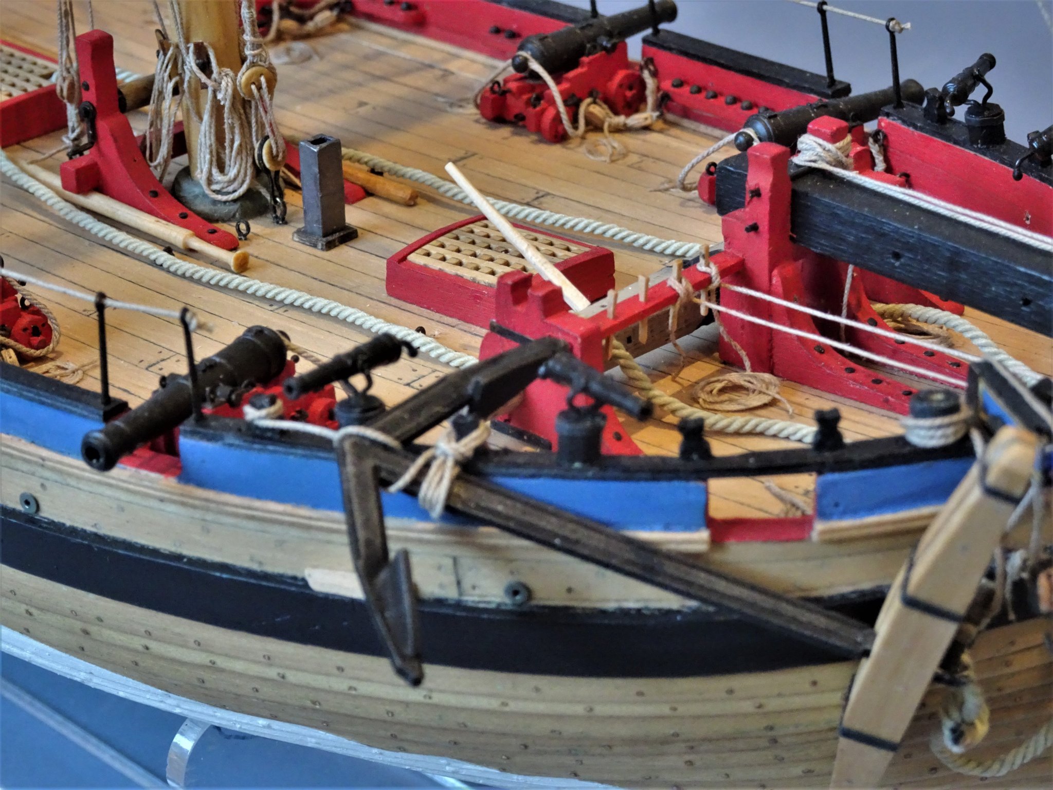
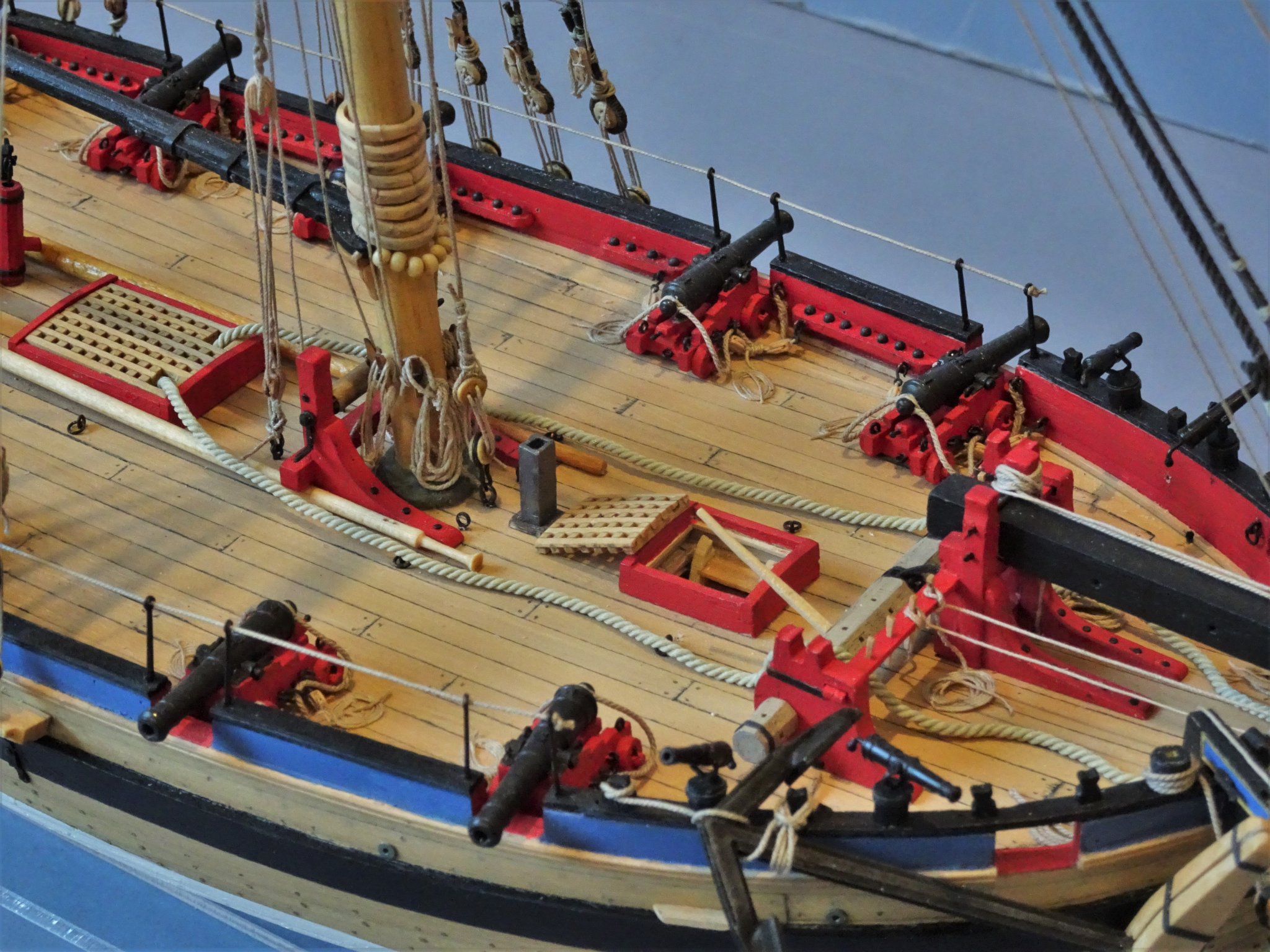
Post 84 Completion shots continued. Upper rigging detail 4875 4897 4874(2) 4861(2) 4869(2) 4864(2) 4865(2) 4883(2) 4884(2) 4885(2) 4889(2) Thoughts about the Alert kit. As I am the first builder on MSW of this new kit offering from the talented Mr Watton it has fallen to me to be the first to record my experience of the kit and build. There is a lot to like about this kit, cutters make fine models of relatively modest size, altho’ at 1:64 scale Alert is large enough for extra detailing and has space when it comes to the rigging stage. It is clear that Chris cares about his customer base and has put a lot of thought into the make-up of the kit providing pre-made parts for many of those areas that new builders may find tricky, but which more experienced builders may wish to replace. That I made extensive modifications is no reflection on the validity of the kit. I accept the limitations of kits and personally I am prepared to take the hit on the additional cost of material and fittings upgrades. Although I have had reservations about some of the supplied fittings, builders of the second edition revised kits will benefit from the improvements made by Chris in relation to the guns and other fittings, and latterly a laser printed deck, and Pearwood grating sets. This is a visually attractive kit, which offers the kit basher a lot of scope whilst providing builders new to the hobby a good oob experience. It has been very tricky deciding how to rig this model given the many variations prevalent at the time, and the often-conflicting information given in the reference sources. The two existing Alert models by Roger Cole, and Irving Kingman differ in their appearance and rigging, and Roger Cole made many changes to both the deck layout and rigging of his model from the Peter Goodwin book which as I have discovered has many conflictions and omissions to confuse the model maker. Irving Kingman also made changes to the deck layout and rigging but did acknowledge that some of the reconstruction of Alert is based on conjecture and therefore possibly not accurate. There is one other Alert model kit on offer, a 1/72 scale card version by Shipyard. A nice-looking model but has the Topmast before the masthead and is rigged in the later standardised form. Part of the appeal of the Alert kit is that it represents a cutter with the earlier style of rigging with the aft placed T’gallant mast and a Square sail set up. I have concluded that there is no definitive example of how Alert was rigged, and I have used many sources to arrive where I am. I certainly don’t advocate my Alert build as the way to go, and I still have many conflictions in my own mind, but the information I have gleaned may be of some use to those that follow and may serve to inform their own decisions. Sources. The Naval Cutter Alert -Peter Goodwin The Masting and Rigging of English Ships of War – James Lees. Eighteenth-Century Rigs and Rigging – K.H. Marquardt. The Global Schooner - K.H. Marquardt. Elements of Masting, Sail-making and Rigging, – David Steel. Seamanship in the Age of Sail – John Harland Rigging period Fore-and-Aft Craft – Lennarth Petersson Alert Provenance and Construction – Roger Cole Modeling H.B.M. Cutter Alert-1777 - Irving H. Kingman NMM plan of Alert. Contemporary Hawke model (NMM) Model of a cutter circa 1785. (Science Museum) I have also scoured the internet for examples of cutter rig, and referenced cutter build logs on MSW. I have enjoyed building Alert despite the frustrations at times and I commend the kit to the members. B.E. 25/03/2020
.thumb.JPG.2c37fafe94e20845ba02b730170e2eaa.JPG)
.thumb.JPG.de6225d484a1cbef4d14d1eca6d49a9d.JPG)
.thumb.JPG.e1362b6bb9c50c4024ed0923decab0f4.JPG)
.thumb.JPG.bd85eb0ca03f5b778645e6bc49efc3e0.JPG)
.thumb.JPG.29935b57d21e8516d6dac8a1ae328279.JPG)
.thumb.JPG.dc019a86106a9787c7d6dcc2da067689.JPG)
.thumb.JPG.3e423f44a586065be04d58b981dd71a8.JPG)
.thumb.JPG.696a07cd3c160f9b8bb60af55eb9804f.JPG)
.thumb.JPG.5291e017c27cb235b9068f1b124cf5f2.JPG)

- 335 replies
-
- 37
-
-
- alert
- vanguard models
- (and 1 more)
-
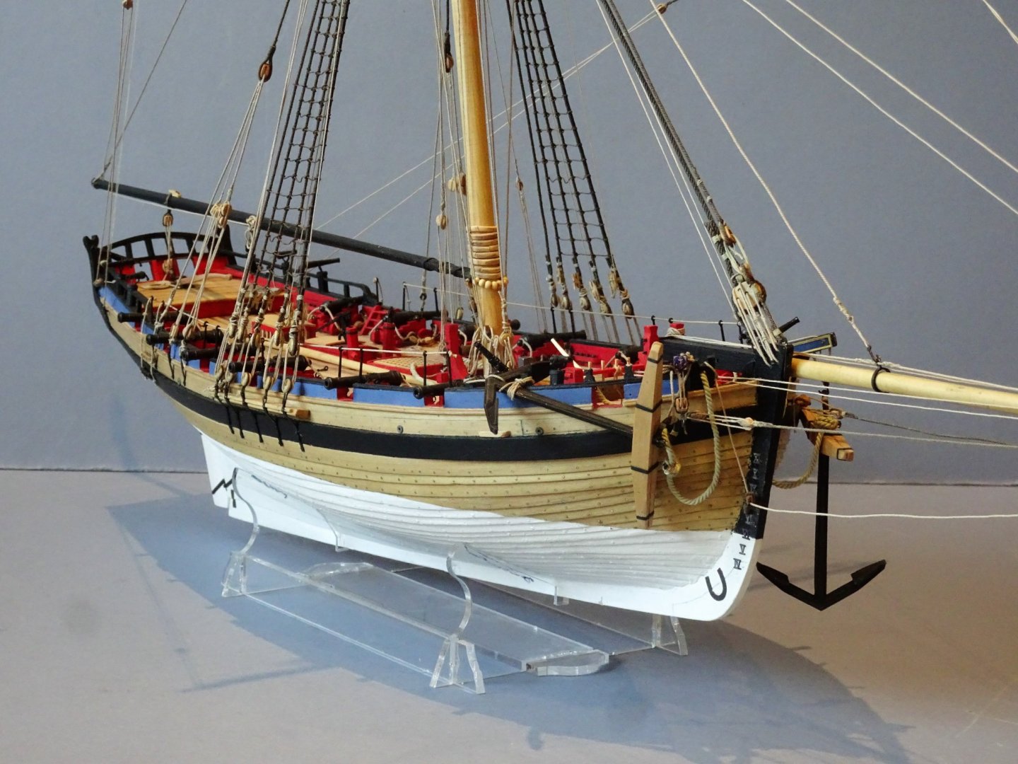
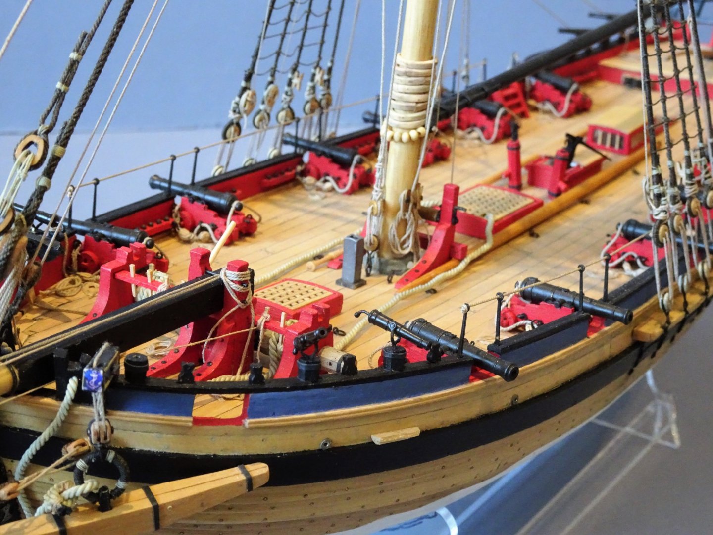
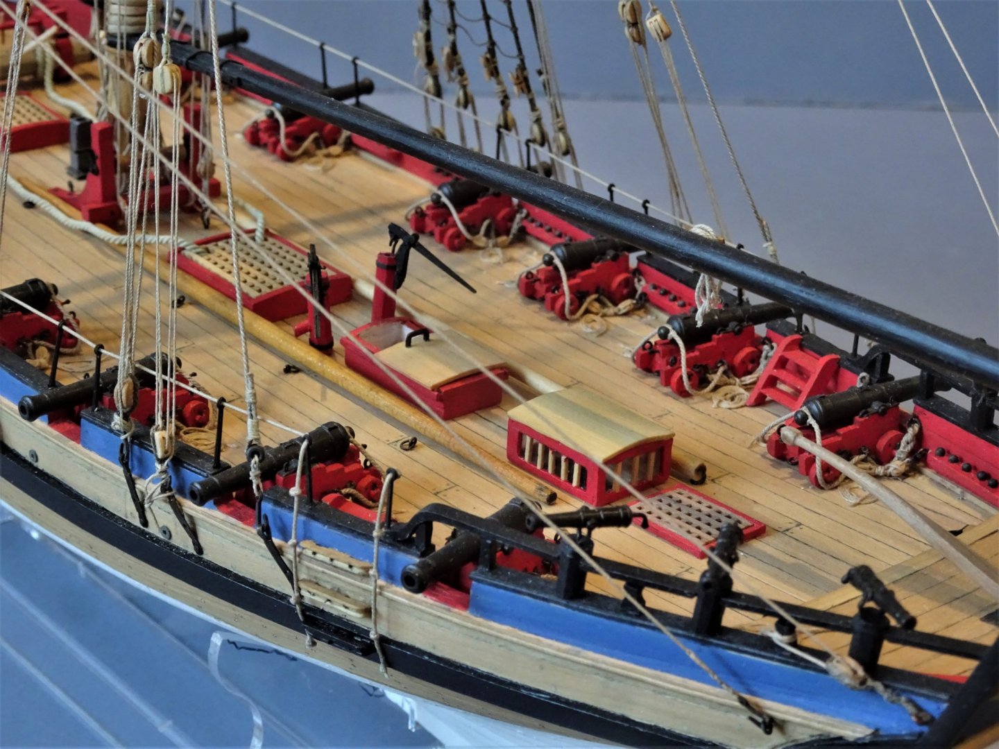
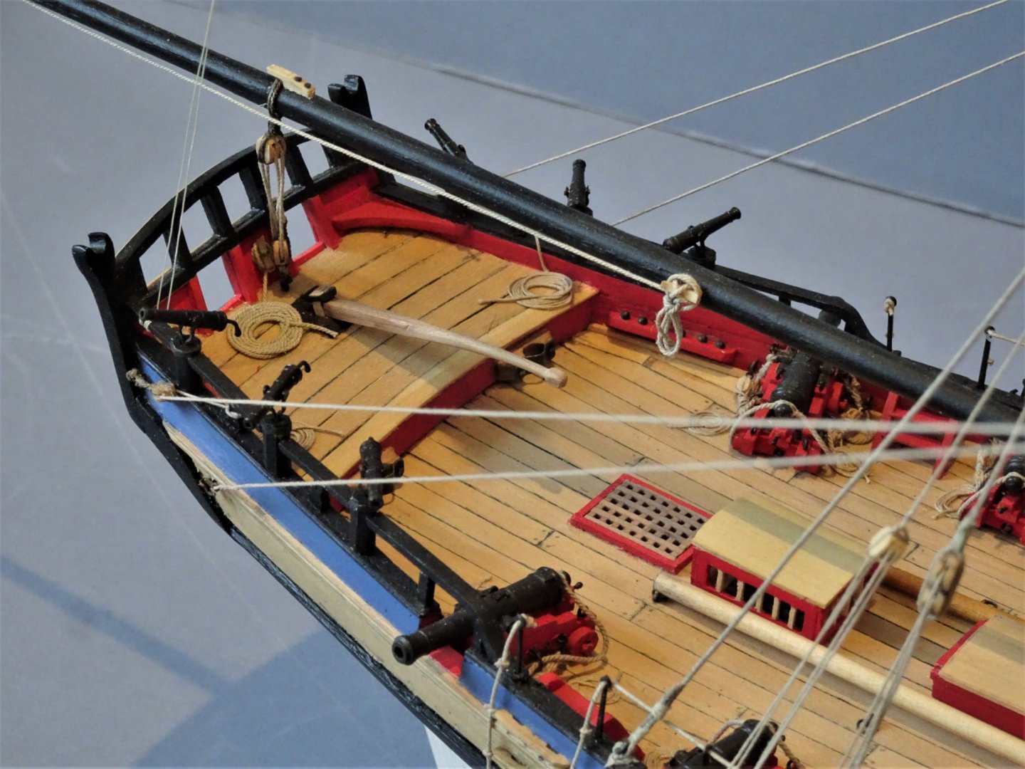
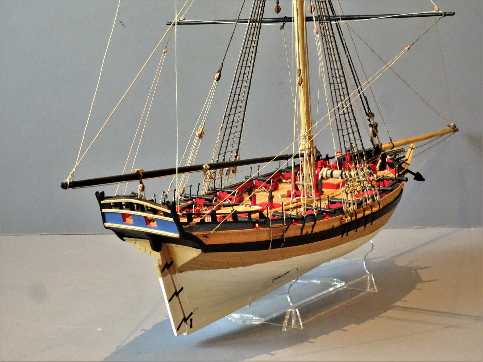
Post 83 All but done Still a base to make but for all practical purposes the model is complete. So here are the final shots of the completed model, I will add my thoughts on the kit and build experience in a separate post. First the close-ups 4870 4878 4879 4891 4898 4880 4893 4873(2) 4876 4886 4888(2) 4868 4895(2) The next post will show the upper rigging shots and full model shots. B.E. 25/03/2020
.thumb.JPG.f5204ef826fc18a135e960d143e8645d.JPG)


.thumb.JPG.d2a019303e5f8927df998ee57158ca48.JPG)

.thumb.JPG.c0c48d327899a397a4923d1230740fbb.JPG)
- 335 replies
-
- 22
-
-
- alert
- vanguard models
- (and 1 more)
-
Very nice work Vane, 👍 B.E.
-
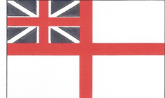
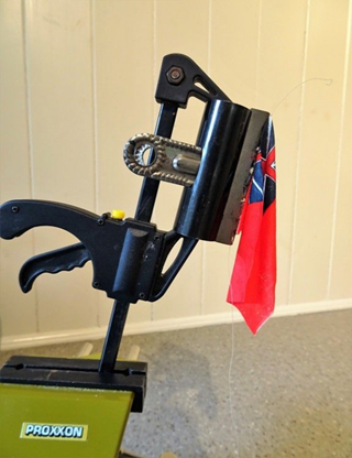
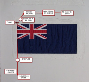
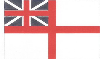
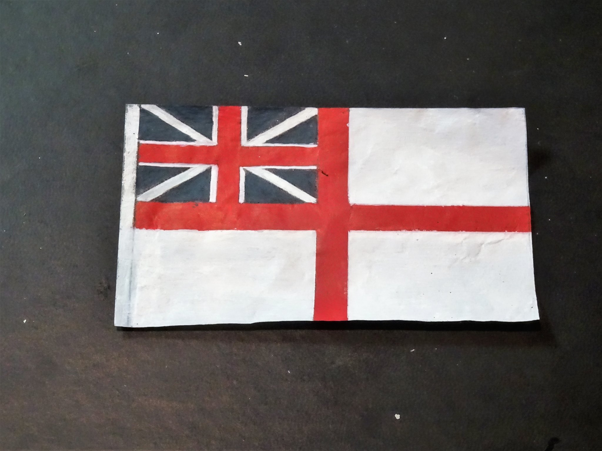
Thanks Jason, Roger Cole did say that he wasn't entirely sure about the Jack being the size of the canton of the largest ensign, but I think there was a fair bit of leeway in flag sizes and on models the eye is probably as good as anything. On square riggers there was the facility to have staffs for harbour display, even when the driver boom came into use, and a staff for the jack was usually attached to the Bowsprit cap. Not too sure about cutters and the like; on Alert I suppose a staff heel could be fitted on the aft deck with a bracket on the transom, but I will fit it to the gaff. Post 82 Making the Ensign Making your own Ensign frees you from commercial restrictions. This is the pattern I have decided upon. For sizing I have settled on 86mm x 54mm which equates to a size of 18’ x 11’4” My primary objective is to have an Ensign that suits my eye on the model. The Ensign is made from Modelspan tissue, overpainted to reduce the transparency. 4810 The Modelspan is stretched over a frame and painted with diluted pva. 4813(2) The modelspan is then taped over a word doc image of the flag. 481(2) Run thro’ the printer the image is transferred to the Modelspan. 4815(2) The image is insufficiently strong at this point so it is taped over polythene for overpainting. The White Ensign is perhaps the most difficult choice because the white ground is not sufficiently white. Red and Blue Ensigns reproduce better. 4816 The Ensign has been overpainted on both sides. The next stage is to attach the halyard connection, I am using 0.1mm line. The excess on the hoist is simply folded over the line and glued. This is a schematic of one I made a while ago. 04840(2) 04841(2) The Ensign is pulled and rolled into shape before raising to the Gaff peak. 4858(2) This post marks the nine month point of the build. B.E. 21/03/2020

.thumb.JPG.b8556ffcf1e29f470dbf6ede9b657cba.JPG)
.thumb.JPG.a57853d12b912870071e805175ade8fc.JPG)
.thumb.JPG.ef868cd5268b5eb491f085ae0a640734.JPG)

.thumb.JPG.1678a68cbb1f9f7429aad6bd009fd122.JPG)
.thumb.JPG.2597ac820e7c567aaf769813db741f18.JPG)
.thumb.JPG.753a0127a7b6716a894e181d199af33a.JPG)
- 335 replies
-
- 17
-
-
- alert
- vanguard models
- (and 1 more)
-
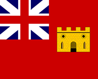
Post 81 A question of Ensigns I like to add an Ensign to a model it adds a splash of colour and making flags and getting them to hang realistically is an interesting exercise. One thing that has puzzled me in relation to the Hawke model is the Union flag at its peak. We know that the rigging of Hawke is original, but a question mark hangs over identification of the model. There is no Naval cutter named Hawke listed, and perhaps the absence of a Naval Ensign is another indicator. The NMM has described it as a Revenue cutter. Revenue cutters did have their own ensign dating from 1694 – a Red Ensign defaced with a ‘castellated gateway’ badge. (1707-1784) Alert, however, was certainly a Naval Cutter and an ensign is appropriate. Alert was attached to the Squadron commanded by Admiral Augustus Keppel, Admiral of the White, so a White Ensign it is. Unusual in modelling, Roger Cole in his build of Alert goes into some detail about flag sizes. Alert would have carried a complement of five different size ensigns or flags ranging from her number one, down through number four, plus a Jack. In size, the fly of the number one was generally about equivalent to the molded beam of the vessel, the hoist was 5/9ths of the fly at this time. The other ensigns were proportional and stepped down where the hoist of one became the length of the fly on the next smaller ensign. The Jack was equal to the canton of the largest ensign. https://www.craftsmanshipmuseum.com/Cole.htm Given that the beam of Alert was 25’10” (The fly) the hoist would be 14’ 4” quite a large flag for a cutter. At scale this would be 123mm (fly) 68.26mm (hoist) Using these proportions, I scaled out the ensigns; The Number one or Battle Ensign does look huge in relation to the model, but the Number two looks a tad small for the model display purposes. No 1 - Battle Ensign No 2 Ensign – General Service No 3 – Storm Ensign No 4 – Harbour Ensign. Jack Many contemporary paintings show the Union flag with a narrower diagonal white cross representing the Scottish saltire. The ground of the flag is also shown as a much darker blue. I have adopted this design which I prefer to the broader white cross and brighter blue ground of many of the commercially available Ensigns. The trick now is to reproduce this as a viable Ensign which will be the subject of my next post. B.E. 20/03/2020


- 335 replies
-
- 11
-
-
- alert
- vanguard models
- (and 1 more)
-
Well done VTH, nice work on the stern planking.👍 B.E.
- 436 replies
-
- 1
-
-
- vanguard models
- alert
- (and 1 more)
-
Thanks for looking in Voyageur, well worth having some heat shrink tubing in your modelling supplies box. 🙂 B.E.
- 335 replies
-
- 1
-
-
- alert
- vanguard models
- (and 1 more)
-
Hi VTH, I bought a small box of mixed tubing a few years ago, probably off e-bay, but a search for heat shrink tubing should bring up a load of suppliers. I found tubing of between 3mm - 10mm diameter the most useful, a little tubing goes a long way. Cheers, B.E.
- 335 replies
-
- 1
-
-
- alert
- vanguard models
- (and 1 more)
-
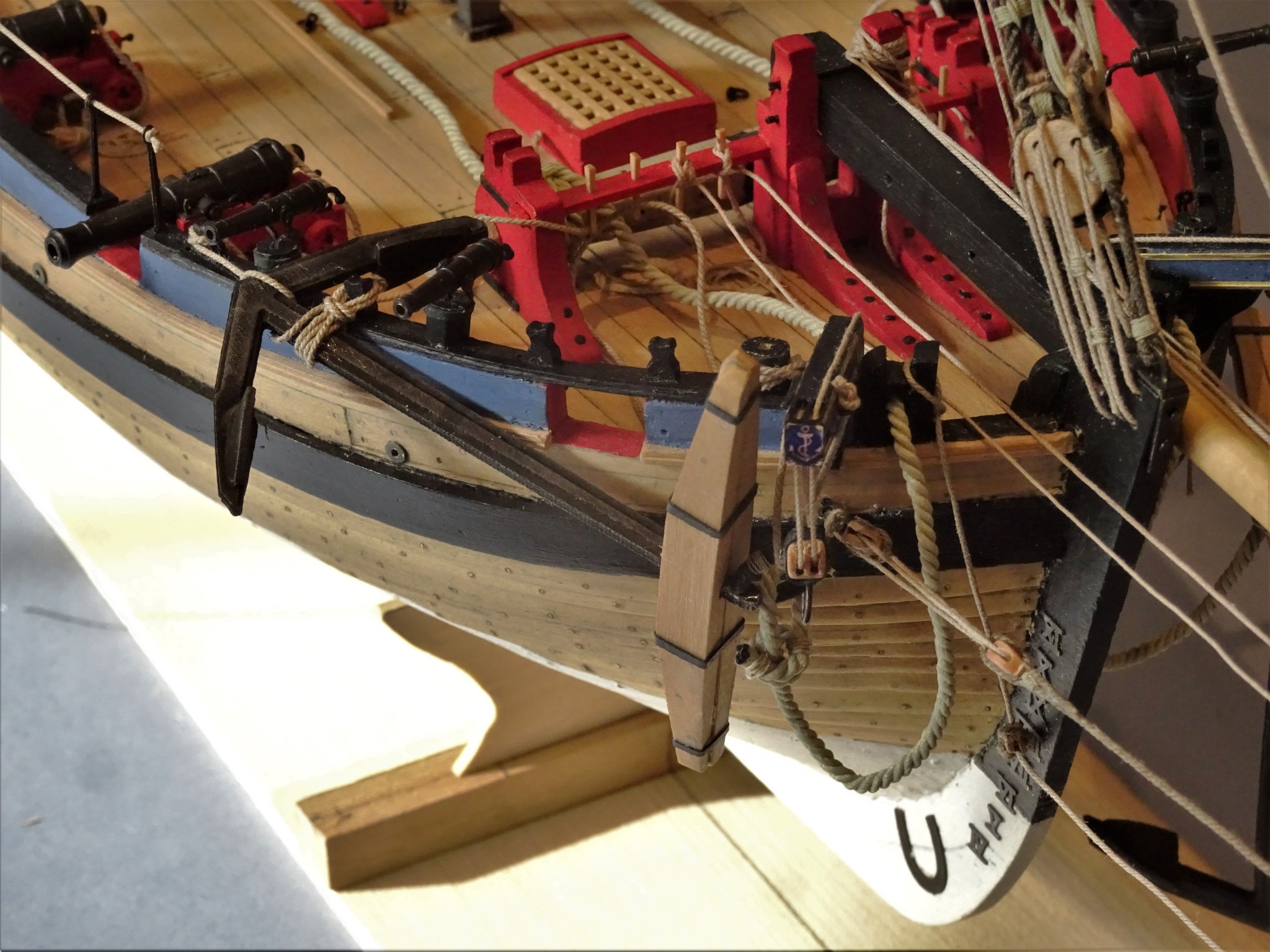
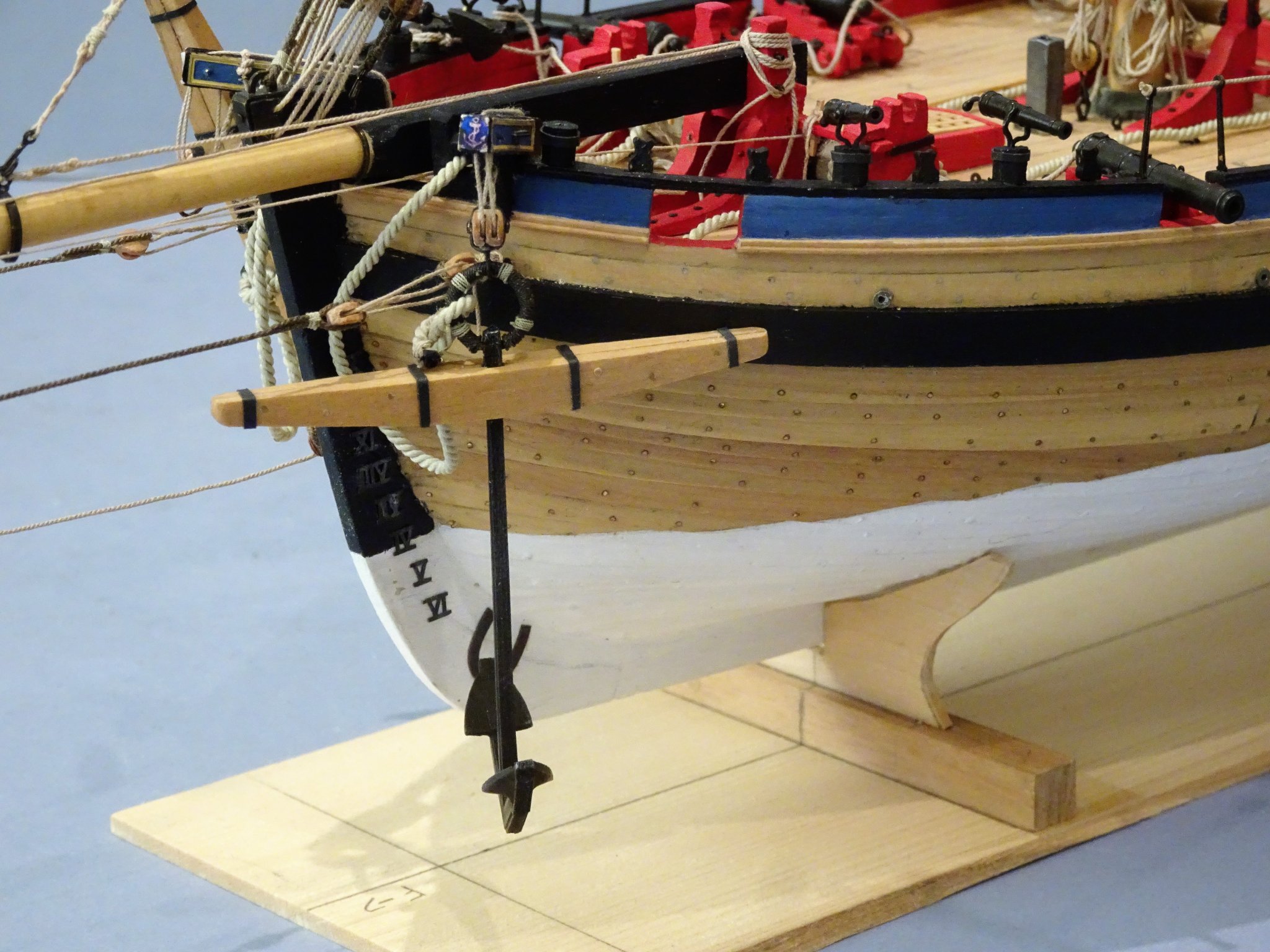
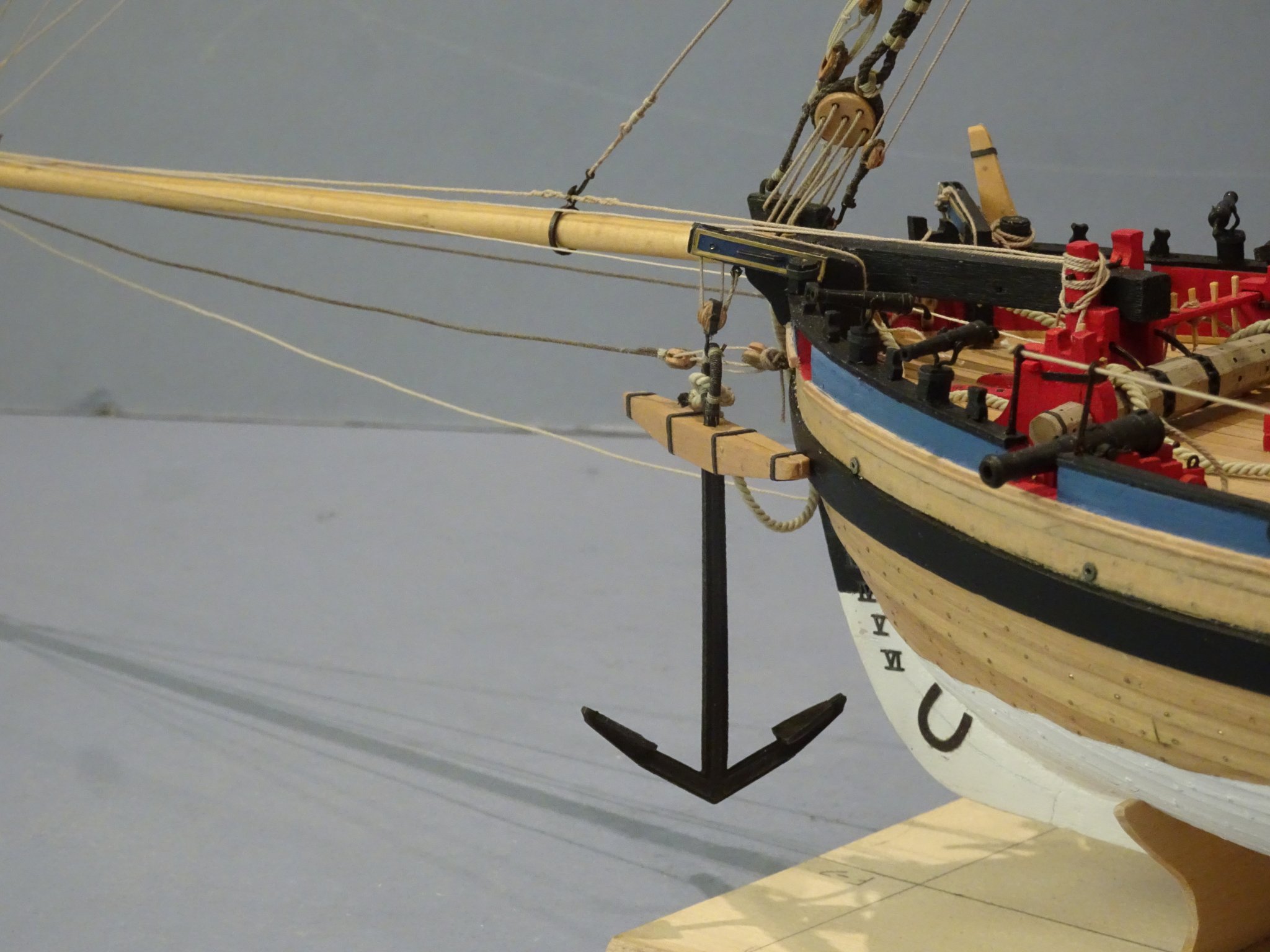
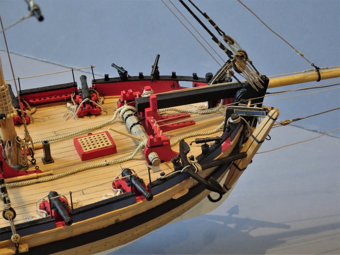
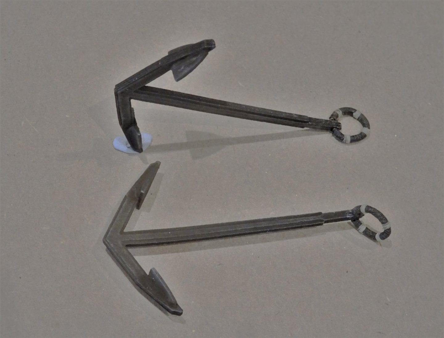
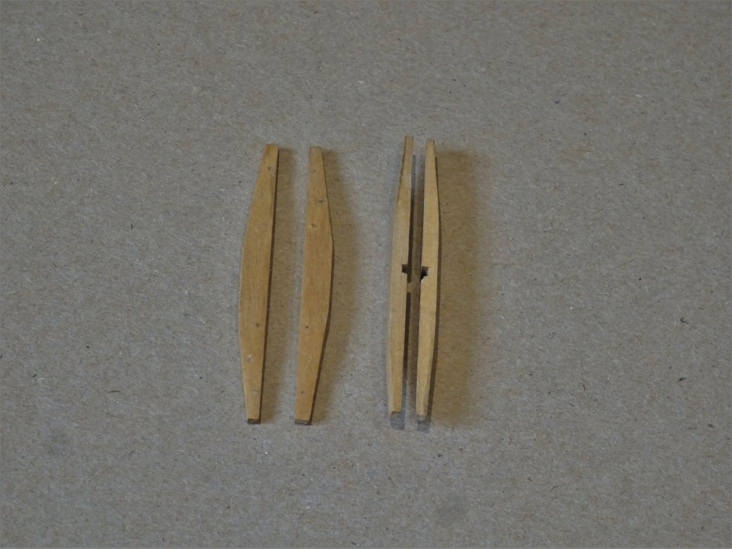
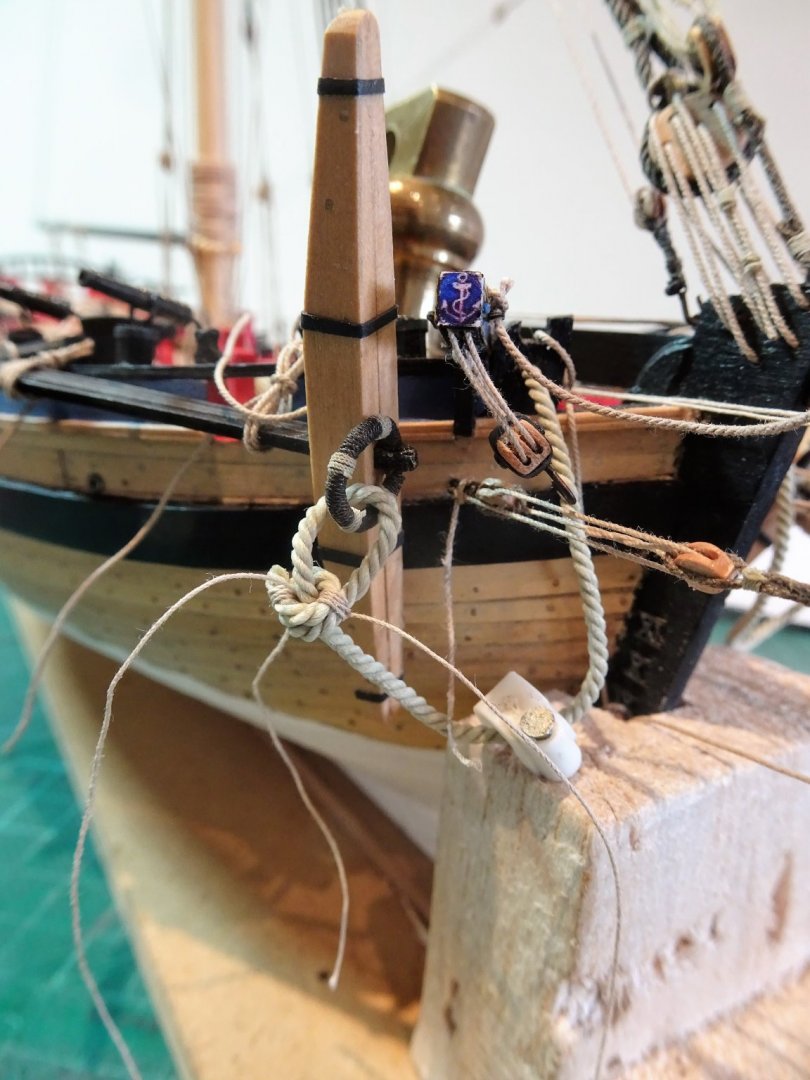
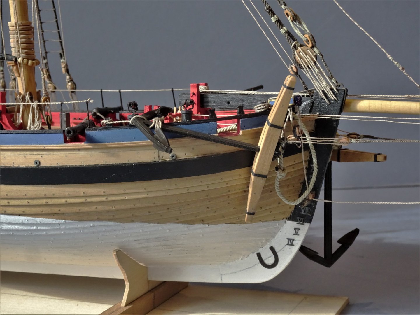
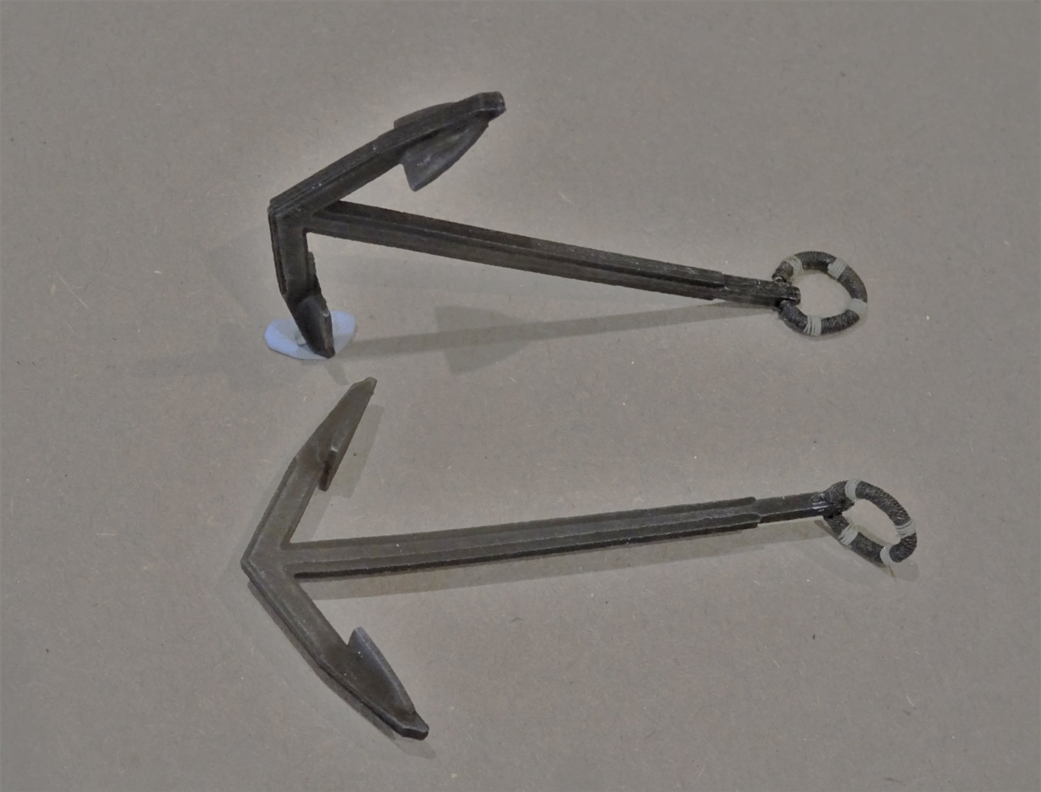
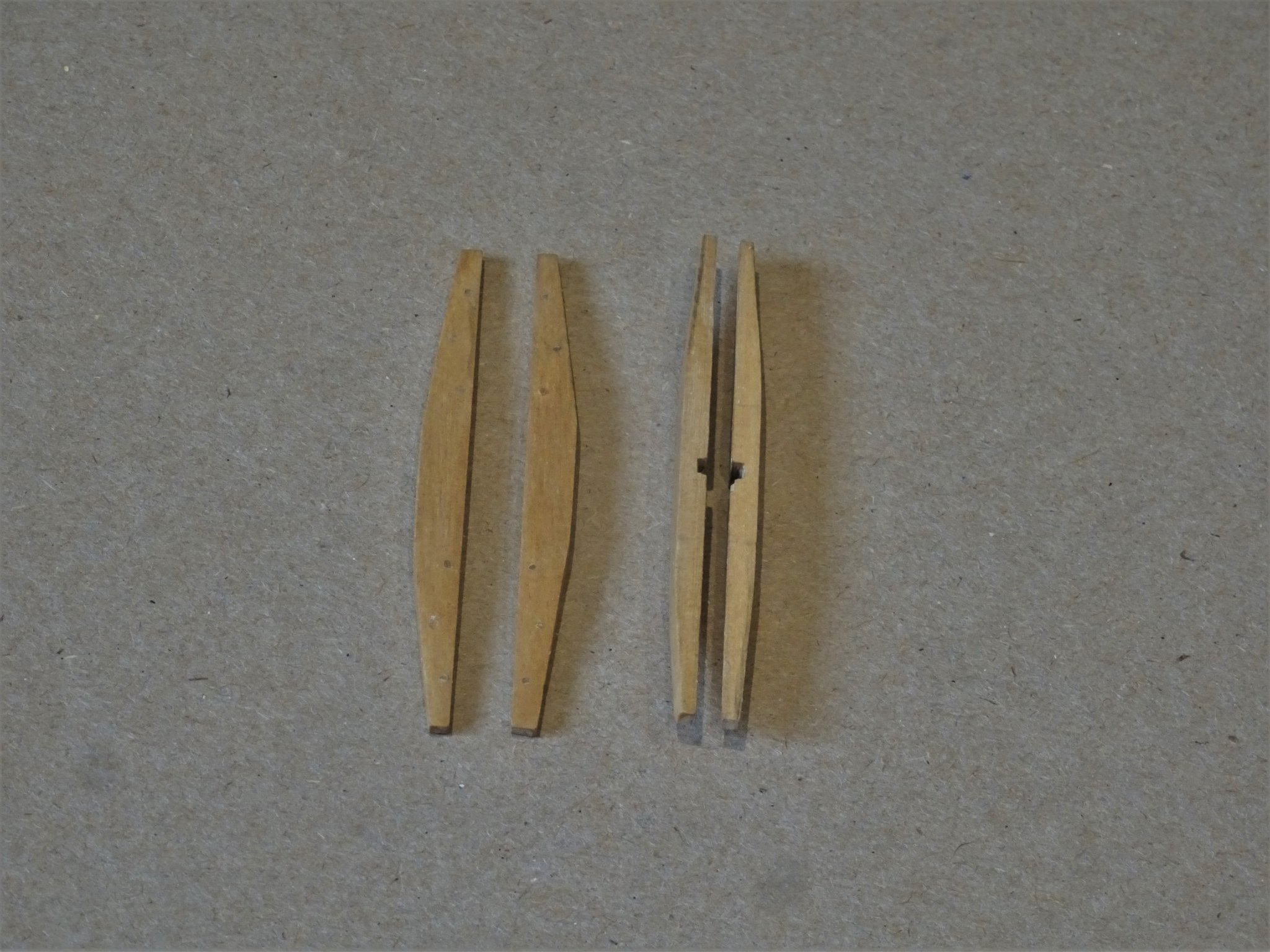
Post 80 The Anchors I had an initial look at the anchors back in Post 47, at that time it was clear to me that while the anchors were ok the kit provided stocks did not pass muster. 3987(2) 4783 Boxwood replacements were made, using the Alert book drawings. The white metal anchors are nicely formed, the only modification I did was to drill thro’ the shaft for the ring. I did need to tweak the anchor shaft a little so that the stock sat square to the arms. Holding the square in a vice and a gentle turn on the arms brought everything into line. According to Steel the Anchor ring would scale to an 8mm outside diameter, with a 0.9mm thickness of ring. I thought the provided kit item a little on the small side and by virtue of its pe origins lacked a round profile. I replaced it using 1mm ø brass wire. 4774 I chemically blackened the white metal anchors using Carr’s Black for Brass; this doesn’t always work, but in this instance it did. 4769(2) I used Morope 0.4mm line for the ring puddening, and 0.1mm line for the four seizings. 4786(2) To represent the iron bands, I took my usual approach of using slices of heat shrink tubing. 4788(2) Saves all that fiddling with Brass strip and silver solder. Fitting the Anchors 4792 Clinching the cable to the ring, a tricky business at the best of times. Starboard Sheet Anchor. 04794 Awkward things to position without fouling other items. 04797(2) 04798 The anchor is secured by the Cat stopper and Shank painter. Port anchor 04801 These anchors do look large for the model, but they are scaled to size. 04804 For display purposes I decided to leave the port Bower hanging from the Cat block. I am undecided whether to complete the Stream and Kedge Anchors, but I can defer that decision until later. I can now carry one and finish dressing the anchor cable. B.E. 14/03/2020
.thumb.JPG.0a4f465db01e0030938c77b0ff5ed81f.JPG)
.thumb.JPG.af1cb9c2b948f7800209ff85098da095.JPG)
.thumb.JPG.9058b0a1fd1e1466c0986b142fdf9311.JPG)
.thumb.JPG.ecbc7c47b469ddf17c96b6bc6761a303.JPG)
.thumb.JPG.a84773362059de4f6e5a55b3cf1ac878.JPG)


- 335 replies
-
- 23
-
-
- alert
- vanguard models
- (and 1 more)
.JPG.54e04a4e19e825eb142a02e3834df119.JPG)

.JPG.d243050ddae870c9824aa671c29608ad.JPG)
.JPG.d412c100b742b1e5276d6f99e8d6edce.JPG)
.JPG.06de6e781a738b169f4a71adcb3e1569.JPG)
.JPG.1a9828ef644080835cfb8d798a91896f.JPG)
.JPG.d6fdfc8a558b6b86f9a39ca7cf00c6bf.JPG)
.JPG.e7c73102dbefb272ac8c7a4b27489ff8.JPG)
.JPG.24695d9deabe54d077c21ee6bef859b8.JPG)
.JPG.8dcef4086d5249699fda630df5ceca5e.JPG)
.JPG.1feb7cb45450d7d2acf1261d6c046256.JPG)
.JPG.4c44741667cdc33686ad433376d5cd0e.JPG)
.JPG.062a0ca642412ae06f3de4dc4c506bbf.JPG)
.JPG.f42b004d47f91ee4b072a8e653d4eefb.JPG)
.JPG.bac3291350fcde42506aae668ad4fc84.JPG)
.JPG.52448efb03245d85fa0f09e4854cf499.JPG)
.JPG.b362719be7fdc8dd41d95cf986b51550.JPG)
.JPG.531bccd082982023640a33ddf097efef.JPG)
.JPG.9a5b9aaac349939f37b4538af661cecd.JPG)
.JPG.1257f31f094df9e6c05988bce546417e.JPG)
.JPG.b90e5f0133d6ec692c3fea5526c3f04b.JPG)
.JPG.e387babade17365817ac1ca5a511cd66.JPG)

.JPG.03e34078c691c0c9cb7b89cc9dbd697e.JPG)
.JPG.45ff25a247bc6cf0d2961f65104cebaa.JPG)
.JPG.7f8071b84176caf83f1db13c9ae2a9b4.JPG)
.JPG.f1ef2de10d652f314ac185539c5729e3.JPG)


.JPG.cb0bb5a4f8ff457593f14997fc2ca471.JPG)


.JPG.1d03b80fe606c571c442b92beff04871.JPG)

.JPG.0bfcf6b05e28434bc4ba5d7c294d2018.JPG)

.JPG.6a38f85712d58329025c5149c2fe948f.JPG)
.JPG.b4c81e71a1d4cc434e82073d23e97ea5.JPG)
.JPG.f53882643612e26b94ab979d20464748.JPG)
.JPG.ea1db9671678e91dab5b59e9a5e8e776.JPG)
.JPG.c207f14ac4c859a8624fb7276e66ae56.JPG)
.JPG.29863349018d62daff8c4956c7099920.JPG)
.JPG.9aa9b3d8015d54eab26d965acb052065.JPG)
.JPG.af9050d483c402a023d2165f2e28e9b0.JPG)
.JPG.4a7cf2c5333bc8c7912fd1e99db08aa7.JPG)
.JPG.4e6605a192c5253d9f581ec0d33c3343.JPG)


.JPG.9be6b45e8533e1ee4ef0ed474fe25cf1.JPG)