.JPG.ca33079f5815b861e67b9c2cccd37982.JPG)

Blue Ensign
-
Posts
4,569 -
Joined
-
Last visited
Content Type
Profiles
Forums
Gallery
Events
Everything posted by Blue Ensign
-

Anchor Question
Blue Ensign replied to rlb's topic in Discussion for a Ship's Deck Furniture, Guns, boats and other Fittings
The first British Round crown anchor was cast in 1813 but only 14 had been issued up to September 1815 (The Arming and Fitting of English ships of war - Brian Lavery) I know little of American practice, but the French and Dutch had introduced the Round Crown anchor in the late 18th century, so it's something that perhaps the American Navy introduced before the British. B.E. -
Cheers Mike, I don't think I have picked up any reference to use of a triangular T'gallant, which illustration are you referring to? B.E.
-
I've mentioned set flying T'gallants quite a bit during the rigging of my Alert, but I think this is taking it too far. Hawke Model 1777 I wouldn't like to be the one to recover that sheet.! B.E.
- 335 replies
-
- 9
-

-
- alert
- vanguard models
- (and 1 more)
-
Interesting set of photo's Jim, thanks for posting them. B.E.
-
Looks a sound basis for the next step VTH, but before you consider it done do a blind feel test, the fingers often pick up irregularities the eye doesn't notice.🙂 B.E.
- 436 replies
-
- 1
-
-
- vanguard models
- alert
- (and 1 more)
-
Not on a fore and aft rig, the Main sheet is belayed in the stern, and the square-sail sheet some distance forward, at least in the kit rigging plan. B.E.
-
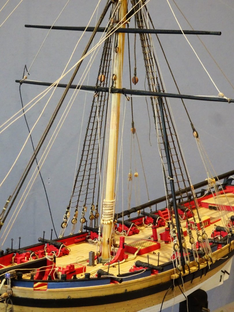
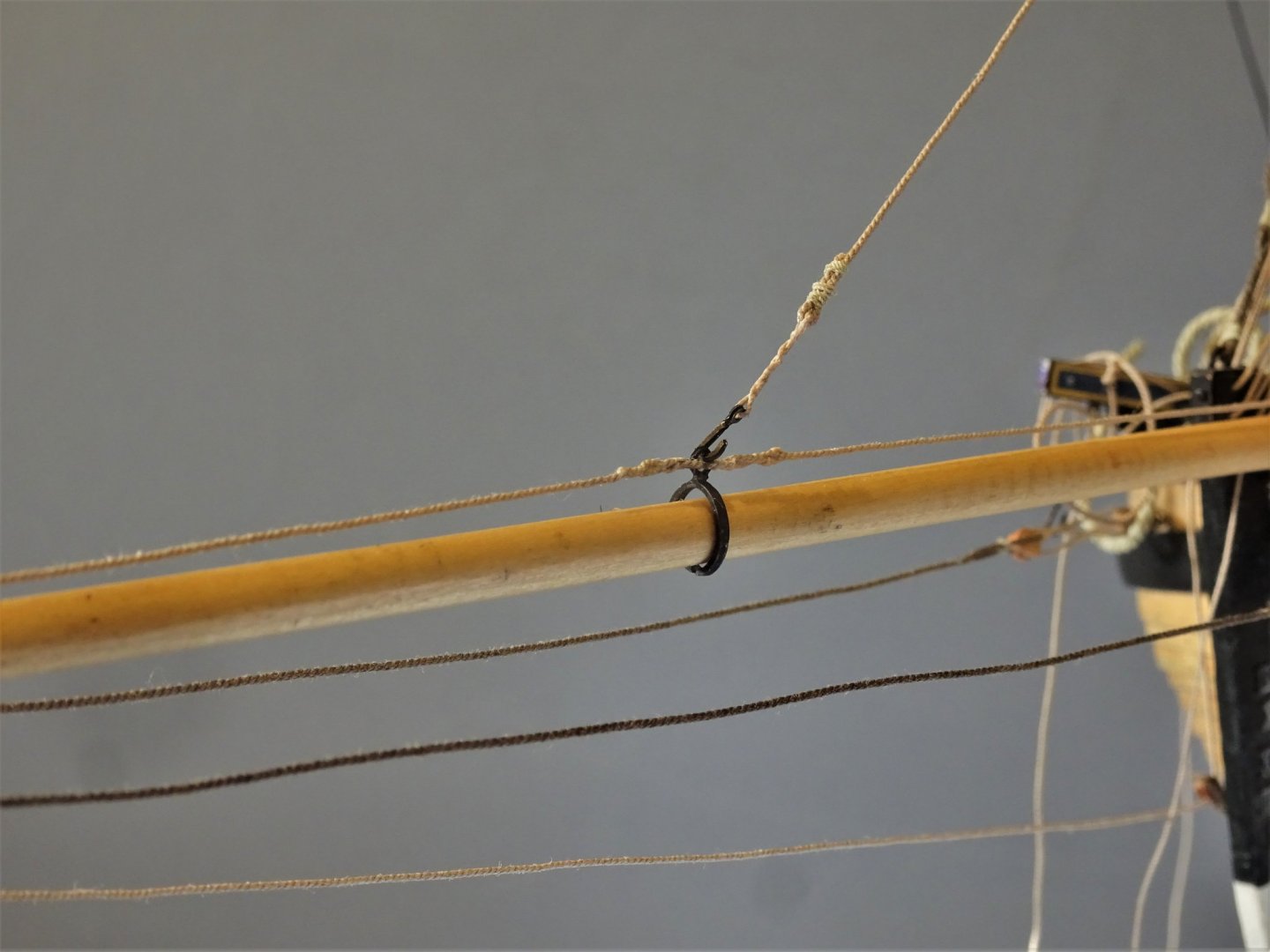
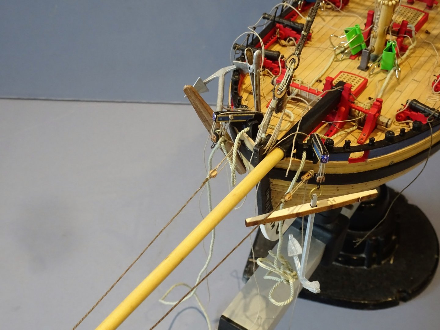
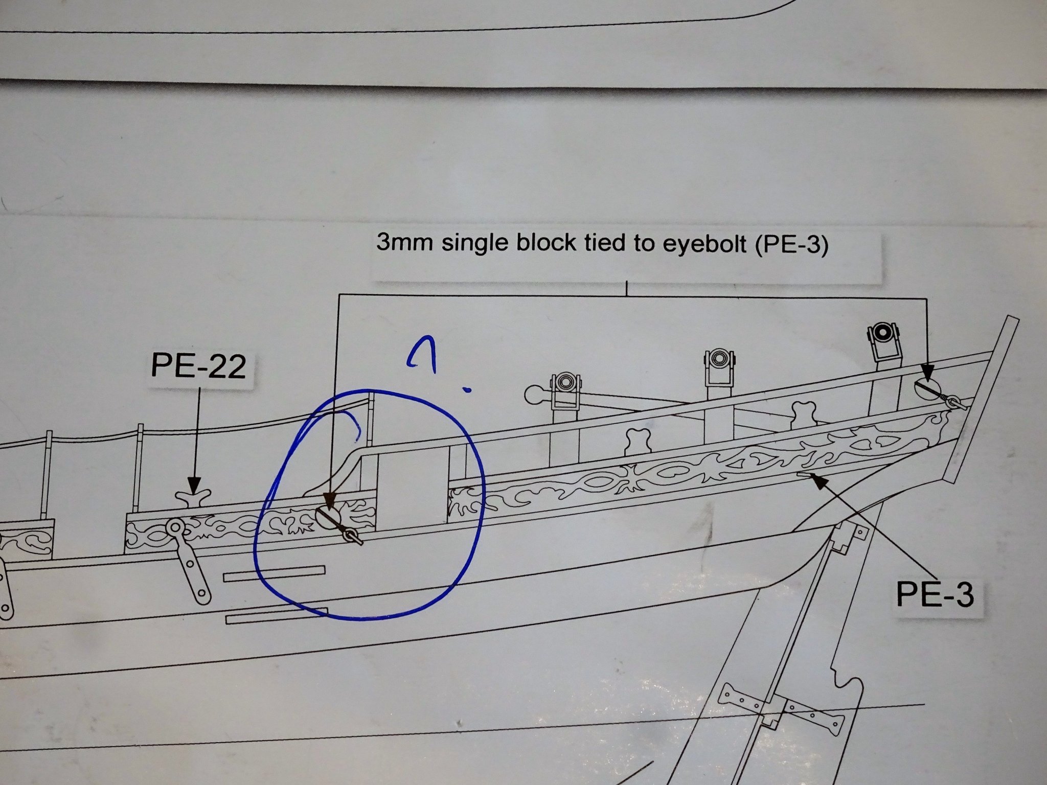
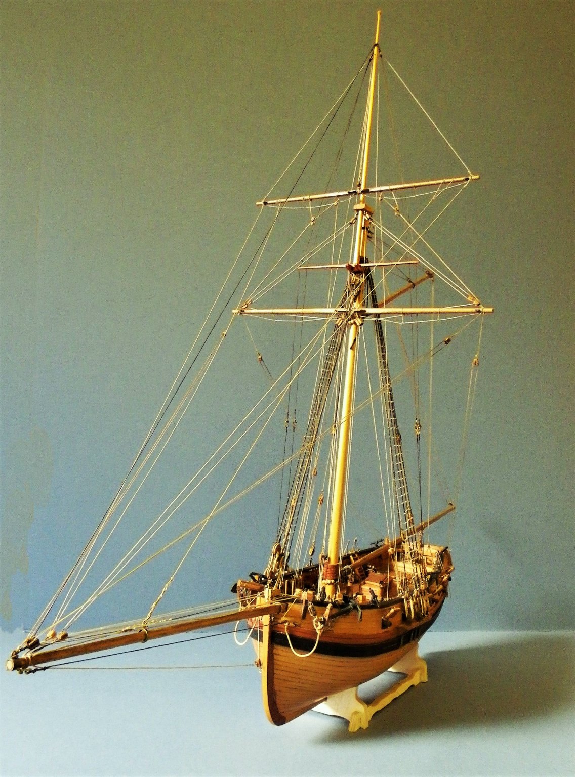
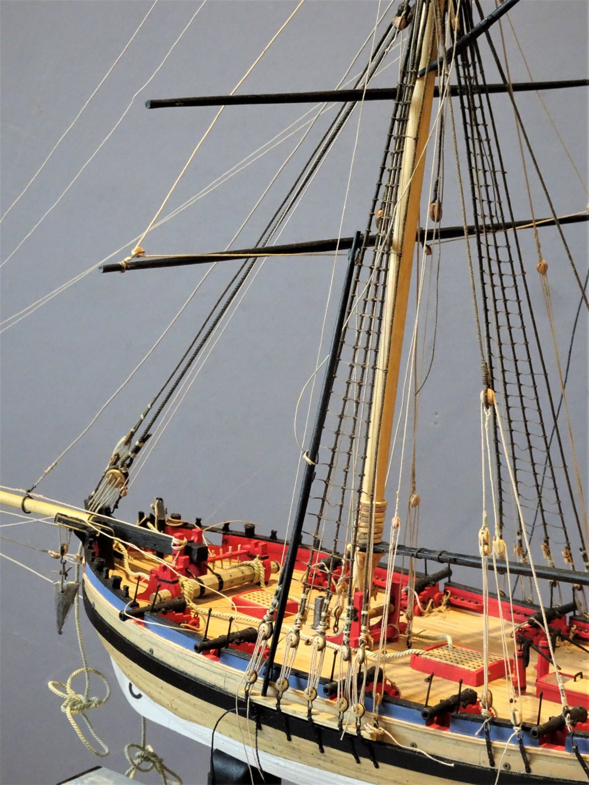
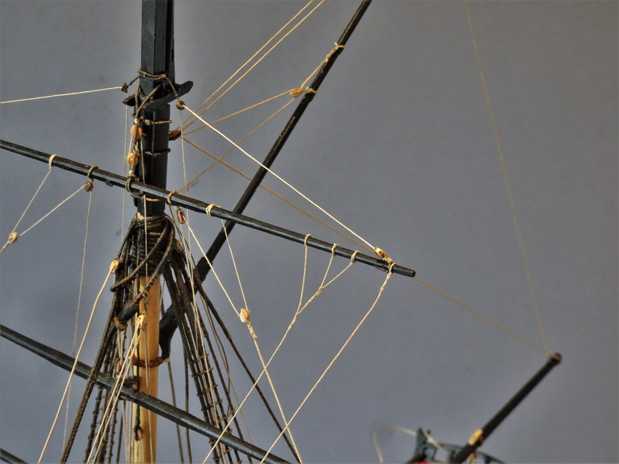
Post 79 Spread-sail yard braces These are fitted with pendents and lead aft. 4754 I am using 0.45mm line for the brace pendents with 4mm pendent blocks, and 0.3mm line for the braces. 4752 I am following the kit arrangement with the standing part hooked to an eyebolt, and with the fall passing thro’ a lead block at the stern quarter to belay around the aftermost timberhead. 4749 These are the last of the main rigging lines to be fitted; just as well as I used the last of my 0.3mm line to complete the job. Fitting is not the same as completing as the process of tweaking the lines millimetre by millimetre, to square and balance the yards will continue, but I don’t think I have any more lines to put into place. There are some ‘necessary’ ropes to put on and the Anchor tackle to fit, but completion of the build is now in sight. On the subject of braces I almost hesitate to mention that I have just noticed that the Hawke model seems to have both aft and forward running braces to the Topsail yard, but I’m not going there. Later rigged models do show both fore and aft rigged braces to the Spread-sail yard, and these are mentioned by Steel. I fitted these to my first cutter model, with the later rig arrangement. 4747(2) 4755(2) T’gallant yard. I have decided that I prefer the look of the yard in place, regardless of actual practice. To my eye it gives the model more balance somehow. A small pin secures the yard to the mast. 4760(2) The square-sail yard is sitting there secured only by its halyard and kept in position by the Topsail sheets. All the evidence would suggest that it would in practice be raised from deck level with the sail attached, but no other tackle is indicated. Roger Cole has added aft running braces to his model, but the Hawke model has none. As Alert is an example of an old-style rigged cutter it would seem perverse not to include the Square-sail yard in the place it would operate, so there it sits; better hope the wind doesn’t get up. 4765(2) Makes me very nervous when I see that Bowsprit with all the long rigging lines, need to be very careful now. 4757(2) At some point I will need to add the Flag halyards, when I get around to making the Ensign. I didn’t follow the kit rigging instructions to any great extent but I did run thro’ them at this point to see if there was anything I had missed. 4746 Not sure what this block is for, no rigging attachments seem to go to it, and it doesn’t appear in the Alert Book. Moving onto the closing stages. B.E. 10/03/2020

.thumb.JPG.7e14b953986c32fbee07a7951c296204.JPG)
.thumb.JPG.0981678f4c4bd429eec943fe991ea3d4.JPG)
.thumb.JPG.018d91802b716a11cabc2298a8ac3c4b.JPG)
.thumb.JPG.fffa2ad509b4ff4c014d0c6391fd48dd.JPG)
.thumb.JPG.e14576b83848d06361d06bc9ce9d5b5c.JPG)
- 335 replies
-
- 16
-
-
- alert
- vanguard models
- (and 1 more)
-
Well done Ian, she looks splendid, no mean feat completing a Heller Victory. Regards, B.E.
-
It's an issue that you will have to decide on when you get around to rigging your Alert model. If you include sails, no problem, if you build her as bare stick, will the sailor in you let you have the T'gallant yard raised and swinging about without a sail bent.😉 B.E.
- 335 replies
-
- 1
-
-
- alert
- vanguard models
- (and 1 more)
-
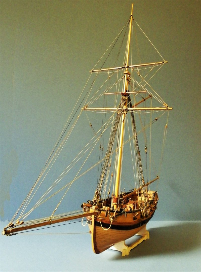
It's only the T'gallant at issue, simply because it is set flying, and doesn't have the usual control lines that would otherwise remain in place once a sail was removed. eg lifts. parrels, braces etc; My understanding is that it was sent up and down with the sail attached as required. This old style cutter rig does seem unwieldy with that square sail arrangement, little wonder it was replaced with a more standardised rig, using the fore and aft sails supplemented by a larger Topsail, and for light winds maybe a T'gallant when a long pole head was fitted. Later style of rig Much easier to rig a cutter with the more familiar Topsail only arrangement as was evident around the mid 1780s B.E.
- 335 replies
-
- 7
-
-
- alert
- vanguard models
- (and 1 more)
-
There's the Roger Cole model , and of course the contemporary Hawke model, which forms the basis of everything that followed in terms of old style cutter rigging. In this instance rigging the T'gallant with sails is an easier option in terms of securing the yard. B.E.
-
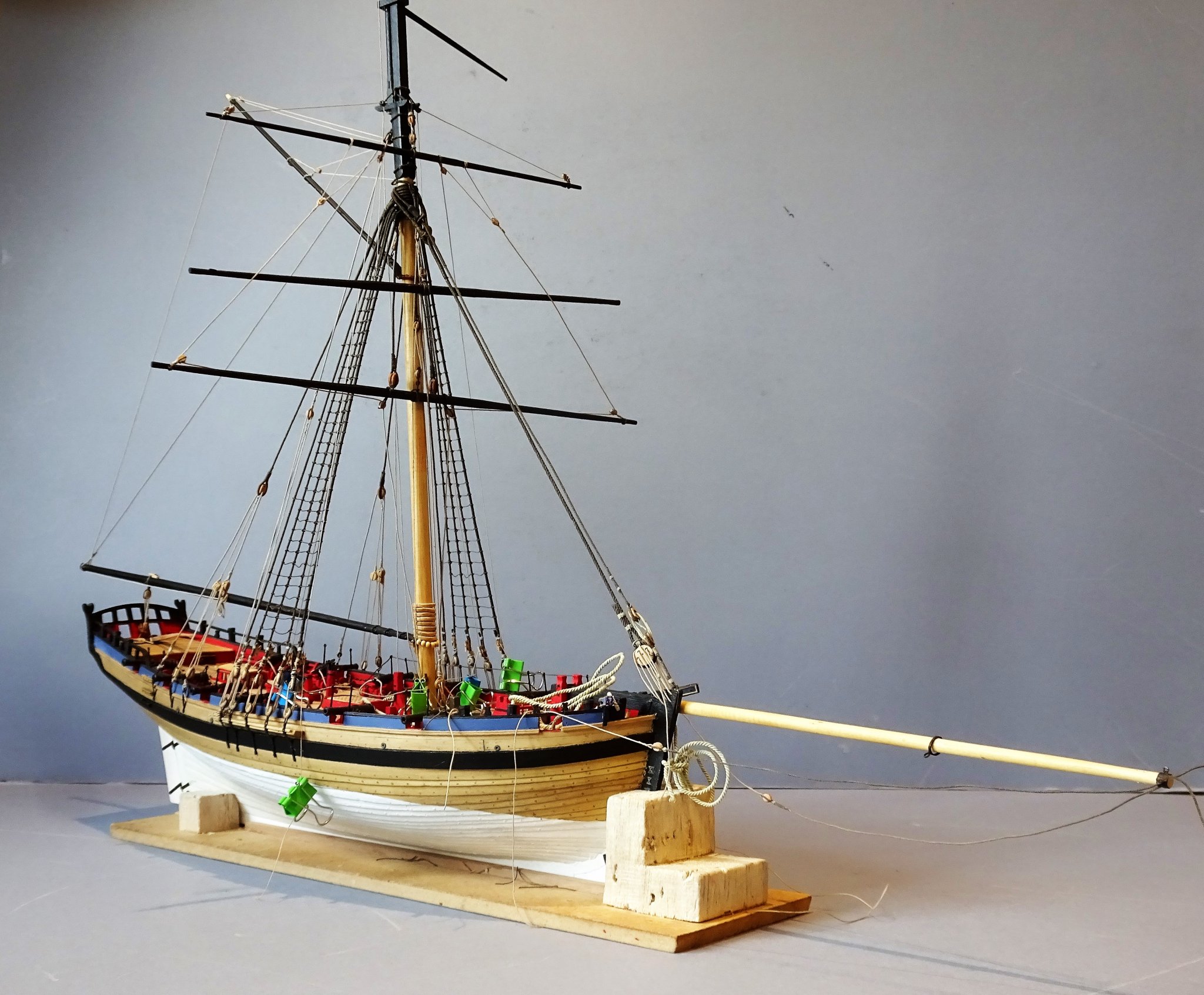
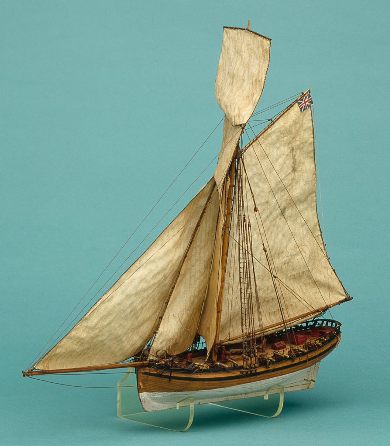
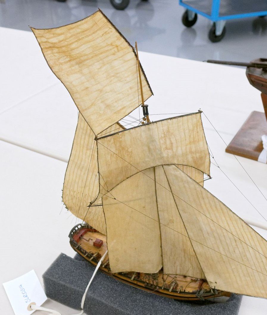
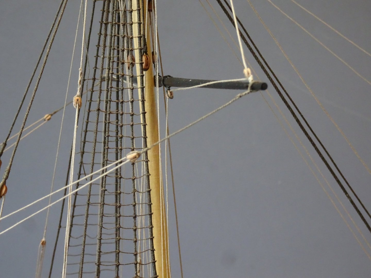
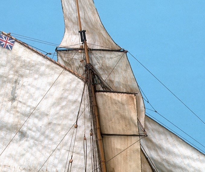
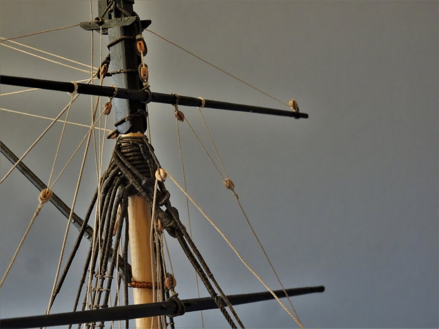
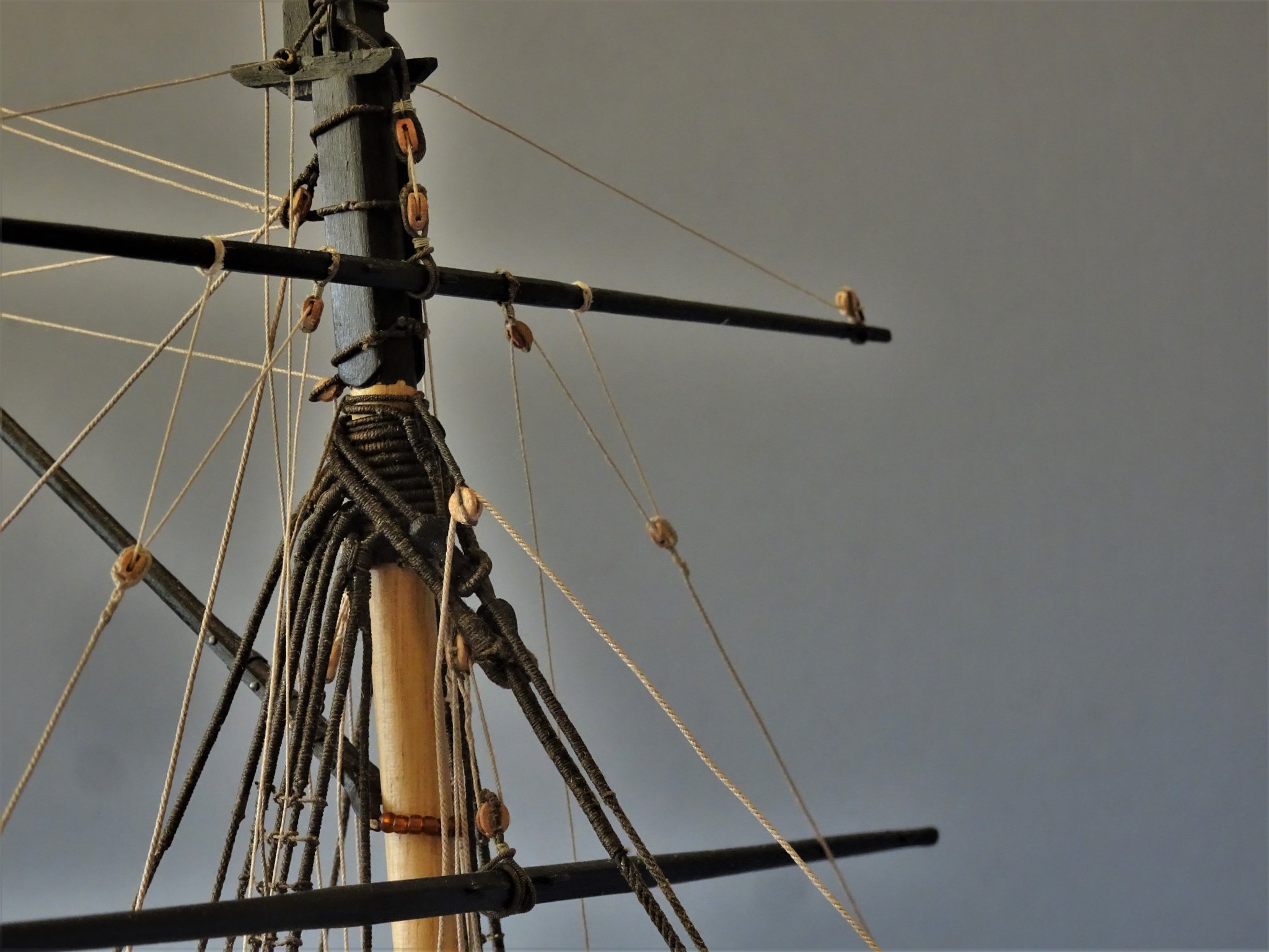
Post 78 What to do with the T'gallant yard From a modelling perspective this is the most difficult yard to secure. It would be simple enough to pin the yard to the mast, add braces and Bowlines and think nothing further about it. I may well come back to this option if all else fails. All the evidence I have read on Cutter T’gallants is that they were set flying. 3302a(2) The Hawke model clearly has no control lines to the T’gallant sail, beyond the Halyard and sheets; no parrel, no lifts, no braces, no bowlines. 3303a(3) With a sail bent it is secured by the halyard and the sheets alone, but without a sail there is nothing to stop it swinging around on its halyard. Marquardt writing in The Global Schooner states that: During the Eighteenth Century t’gallant yards were generally set flying and rigged only with a halyard and occasionally single braces. Harland refers to T’gallant and Royal sails being bent to the yard at deck level and taken up with the tackle already attached. This would indicate that without sails the yard wouldn’t be in position and would be lowered and lashed perhaps to the shrouds. Harland has a lot to say about sending light yards up and down. He describes that on ships in harbour it was almost a sport to regularly run the yard up and down, partly as a training exercise for the more arduous conditions at sea, but grace and speed in carrying out the exercise was an important feature. He describes the procedure for raising and lowering but it relates to a T’gallant with both braces and lifts, which are used in the process, but which are absent in the simplified rig of a cutter. 4720(2) The more I read the more I am thinking that having the bare stick yard in position does not represent a realistic situation. In modelling terms having it there does perhaps balance the look of the model and indicate the use of a T’gallant, so I am undecided which way to go. 4734 When not in use it should be more realistically stowed against the port side shrouds, but the question then arises how the yard was secured, was the Halyard still attached, and what tackle was kept with it. 4738 It would be simple enough to seize the yard to the fore shroud, but I don’t think that is enough. As a non-sailor, I struggle to understand the mechanics of how these things were done, particularly on procedures in place 250 years ago. I need to get my head around the detail given by Harland, and how it would relate to a cutter, but purely for aesthetic reasons, if I don’t like the look I’ll probably go back to plan A. (just run it up without canvas for practice Guv’nor) 4742(2) So, Gromit what d’ya think. Sometimes I look back with fondness on those novice days, happy to assemble kits with a mind uncluttered by such detail. Hey Ho B.E. 08/03/2020

.thumb.JPG.ddc5e6d45dbfb1681e235e5c19fe30af.JPG)
.jpg.0db54cf04ce8ebfe52c539293025a803.jpg)
.jpg.2d9626a50fd9b9aee80ee8b6a628316d.jpg)
.thumb.JPG.1dbc6d6059a4d74ca4446749b50445a3.JPG)
- 335 replies
-
- 19
-
-
- alert
- vanguard models
- (and 1 more)
-
Thanks Spy, as my old Dad would say, it looks even better to a blind man on a galloping horse. 😉 B.E.
- 335 replies
-
- 2
-
-
- alert
- vanguard models
- (and 1 more)
-
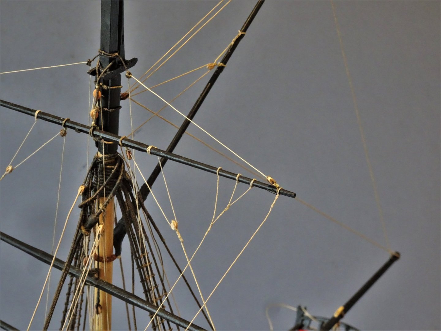
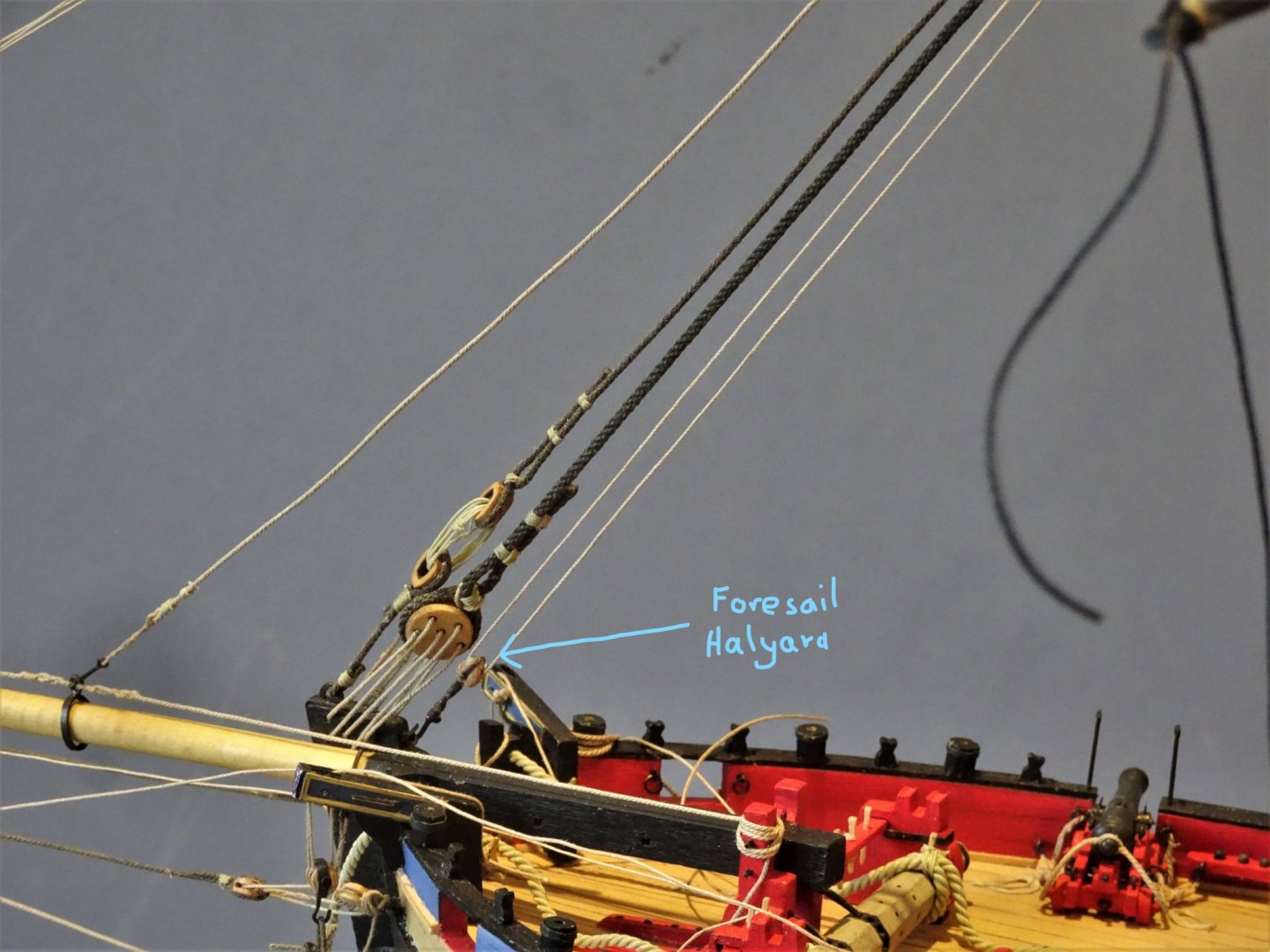
Post 77 Rigging around the sharp end resumed. Changing my mind about the Foresail halyard. The Foresail is bent to the Forestay using hanks. The kit arrangement has the halyard tackle running between the halyard block and a block secured beneath the Forestay collar and down to the winch bitts. 4727li For the purposes of display I have hooked the tackle to an eyebolt in the stem, run it thro’ the stay block, and down to belay. This is a lighter line than the halyard used for the jib, (I have used Syren 0.30mm) This is what Steel has to say. FORESAIL Bends with hanks to the stay. HALIARDS reeve through a block, lashed underneath the collar of the stay at the mast-head, and a block lashed to the head of the sail: the standing-part makes fast round the mast-head, and the leading-part comes down upon deck. Unlike the jib arrangement Steel makes no mention of a falls tackle. On this basis I have decided against fitting a deck tackle. 4728(2)li The kit instructions indicate the belay at the winch cross piece, and the arrangement is also shown by Petersson (Rigging period fore and aft craft) except he has the belay to a pin on the portside rack. (not an option on Alert) So, the winch cross piece it is, and I imagine in that position the winch could be used to assist the hauling. Bowlines I have followed the Alert book arrangement for the Topsail Bowlines using 3mm blocks separately stropped behind the cranse. 4721(2)li Note: - only a double block for the Topsail Braces. I decided not to fit a T’gallant Stay on the basis that a) Hawke doesn’t have one, and b) the drawings in the Alert Book which show the stay are at variance with the narrative by Peter Goodwin. The kit rigging has the Bowlines simply secured to the yards. I’m not sure that they are a required feature on a bare stick model, but they do help stabilise the yard so I will fit them. In practice the bowlines were attached to the sails by bridles which should be reflected on the model if fitted with sails. The Hawke model only shows bowlines attached to the Topsail. Harland, (Seamanship in the Age of sail) in discussing the Bending, loosing, and furling a sail refers to Bowline bridles being permanently fitted to each topsail and kept with the sail. However, there are examples of contemporary 18th c models with the bridles attached to the yards. The Atalanta model is one example, the Ipswich another. Lees, (Masting and Rigging of English Ships of War) comments: When models are not fitted with sails the bridles are timber hitched to the yard a little inboard from the yard arm cleats. So, the choice is to simply hitch the lines around the yard or make up the bridles and attach those instead. The pedant in me draws me towards fitting the bridles despite the additional work involved. 04713 A little fiddly to set up and match each side, one of the main problems is getting the bridles to hang naturally, and for this I weight them and paint with diluted pva. 04719 Port side Topsail bowline and bridle in place. It helps to rig temporary aft running braces to the topsail yard to assist with the tension of the bowlines. (I don’t have a tye or parrel to haul against) 4718(2) The diluted pva has done its work, the bridles remain untwisted. 4724(2) Topsail Bowlines and braces in place. I quite like to have a little natural sag in the bowlines and I will be working towards this effect. The Alert Book indicates brace pendants to the Topsail yard, but these are not reflected on the Hawke model, or for that matter on the Roger Cole model of Alert, whereas he does show brace pendants on the aft running braces. Brace pendants were a feature of yards of this era, but I wonder if given the fairly small size of Alert, and the deeply gored Topsail, this was deemed unnecessary. I decided to simply splice the Topsail braces to the yardarms. Square sail Bowlines The Hawke model does not show these fitted, but Steel mentions them. SQUARE-SAIL OR CROSS-JACK Bends similar to a ship’s main or fore course. BOWLINES reeve through a sheave in the double-block on the bowsprit-end, and on the bridle at the sail, the same as a ship’s. The leading-part comes in upon deck, and belays round the bitts. I think that Steel writing in 1794 may be referring to a later arrangement and set-up for the Square sail than operated with the old cutter rig. The kit also shows bowlines fitted to the square-sail, leading thro’ a double block in the stem and to the bitt rail on the windlass. Marquardt mentions *Bowlines set up to the Square-sail, thro’ a double block at the end of the Bowsprit and belayed on the bitts or cleats on the inner bowsprit. T’gallant sail Bowlines Included in the kit instructions, but not mentioned by Steel, or evident on the Hawke model. Goodwin also says that: -* Bowlines and bridles were omitted from the T’gallant and Square-sails as both were generally set flying. With Goodwin this is another case of the words and drawings being at odds with each other. Drawings H6 and H7 indeed show bowline bridles. I am going to stick with the Hawke model example and omit bowlines from both Square-sail and T’gallant sail, but it is evident there is wriggle room on the approach to take. The Topsail yard rigging will now be tweaked to hold the yard steady, not such an easy task given that the yard is not secured to the mast. B.E. 07/03/2020
.thumb.JPG.293486b95cb8bc8b1a62538fea688ac1.JPG)
_LI.thumb.jpg.ae8d6df414e51ee1661b0cfd86058a60.jpg)
.thumb.JPG.ee905763cb8669a5cc4bff67956645f6.JPG)
_LI.thumb.jpg.661bc053ff3c10e0ad8f95c92650b0c9.jpg)
- 335 replies
-
- 12
-
-
- alert
- vanguard models
- (and 1 more)
-
Thanks Spy, I’ll take a while to digest all that. My thinking is that the jib sail was a large affair, on a substantial line, set flying, without a jib stay, quite a thing to haul on without the benefit of a tackle. The outhaul didn’t seem to have a tackle, neither did the inhaul, but I’m quite comfortable with the rigging of those. It is the halyard belay that was giving me a headache, but Steel indicates one was set up, the question is exactly how. Incidentally on my Cheerful build which I didn’t rig, the halyards are shown as simply belayed to the mast cleats, but that would be the easy option😉 B.E.
-
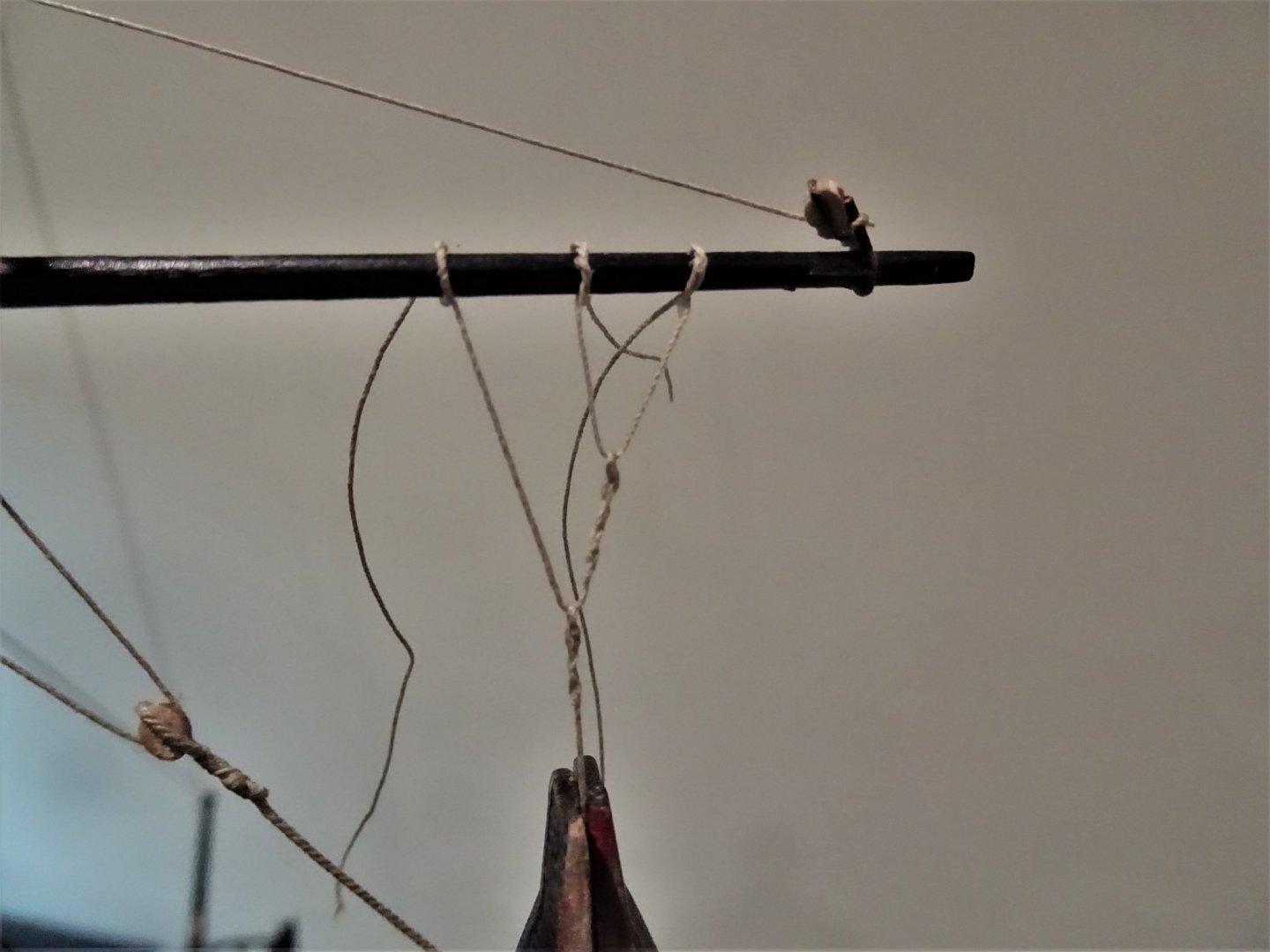
Post 76 Jib Rigging – what’s that all about Jib Outhauler This is variously called the jib sheet (Kit Instructions), outhauler, or inhauler running aft, according to which drawing you look at in the Alert Book. 4657 I call it the jib outhauler; attached to the traveller and runs thro’ the sheave in the Bowsprit end. 4651 It passes thro’ a single block attached to the cutter stem before belaying to a timberhead adjacent to the Cathead. Jib Halyard To fit or not to fit on a model without sails. I have seen jib halyards fitted to many bare stick models both contemporary and modern. 4650 The Alert book shows the tack of the jibsail attached to a jib tackle hooked to the traveller ring. The peak is attached to the halyard which passes thro’ a block at the masthead above the Fore-stay and then down to belay. Unfortunately, how and where it belays is left to our imagination. The kit arrangement has the tack attached to the outhauler which passes thro’ the ring atop the traveller. The peak passes thro’ a block as with the Alert book, and belays abaft the mast to the winch bitts. Without sails it suggests the outhauler is toggled to the ring. Steel has a lot to say about the jib halyard rigging. MAIN-JIB-TACK is clinched through the swivel-eye in the traveller on the bowsprit, then reeves through a sheave-hole in the end of the bowsprit, and through an iron-bound-block, hooked and moused to an eye-bolt in the side of the stem near the water, and then brought to the windlass over the bow, and hove out; then stopt and belayed round a timber-head. HALIARDS reeve through the block lashed to the head of the sail, and through the block on each side the masthead. One end has a treble-block spliced or turned in,and connects by its fall to a double-block, that hooks to an eye-bolt in the deck on one side, and the other end belays to an eye-bolt opposite. DOWNHAULER makes fast to the head of the sail and leads upon deck. INHAULER makes fast to the traveller and leads in upon deck. This is a lot more rigging in terms of tackles than suggested by either the kit or the Alert Book, but he is writing in 1794 presumably about the modified cutter rig. According to Steel; The halyard is 5” c line (0.63mm ø) 14” blocks ((5.5mm) tackle fall 3½”c line (0.44mm ø) The kit indicates 0.5mm line and a 3mm block. No tackle is shown, with the halyard simply secured to the winch bitts. 4654 I fitted a 4mm block in a strop above the stays, I rigged a jib tackle as per the Alert Book and hooked it to the traveller rig. 4656 Using Syren 0.63mm line for the halyard I seized one end to the jib tackle and the other end passed thro’ the lead block at the masthead. I am now presented with a dilemma as to how to proceed. The Halyard is a long fairly hefty line, would it really be worked without tackles at the deck level? Annoyingly in all the photo’s of contemporary models the detail of the lower halyard rigging is obscured or missing. Marquardt offers a glimmer of hope referring to (the halyard) might also be rigged single, being bent to the head of the jib and reeving through a block at the masthead upon deck, where a double block was turned or spliced into the end and a fall connected this to a single block hooked to an eyebolt. I have rigged up such an arrangement. 4660 I can’t really attest to its validity, but my inclination is that it’s perhaps preferable to simply hitching it to the winch rail. 4659 As far as I can see there would be a corresponding arrangement on the Port side for the Fore-sail Halyard. I’ll let that percolate for a while and see if I’m happy to let it stay.🤔 B.E. 03/03/2020


- 335 replies
-
- 16
-
-
- alert
- vanguard models
- (and 1 more)
-
Ha, ha, Spy, I daren't stop now I might not have the momentum to pick up again. Fiddling with tiny blocks and strops this morning, spending half the time on my knees searching the floor before my canine assistant finds them. That would be ok but it's finders keepers as far as he is concerned. B.E.
- 335 replies
-
- 13
-
-
- alert
- vanguard models
- (and 1 more)
-
Thank you Nils, good to hear from you. @ stuglo - thanks for looking in, I hope it serves to assist rather than confuse, I have drifted quite a way off piste relative to the kit instructions, and I often confuse myself.🤔 B.E.
- 335 replies
-
- 2
-
-
- alert
- vanguard models
- (and 1 more)
-
Great pics Spy, thanks for the info. I note that the Bowsprit shrouds on which the Bosun is sitting don't interfere with the raising operation, which was my main concern with the model set up. Regards, B.E.
-
Thanks Eamonn, It's always difficult to understand what went on back in the eighteenth century, particularly as a non sailor from the 21st c. I scoured my reference sources looking for clues that may explain why things were as they were, and Harland in particular (Seamanship in the age of sail) covers the raising and dropping of the anchor in detail, even down to the sequence of commands, with no reference to clearing the shrouds. In terms of the model, it just looked odd to my eye so I couldn't leave it alone. 🙄 Regards, B.E.
- 335 replies
-
- 1
-
-
- alert
- vanguard models
- (and 1 more)
-
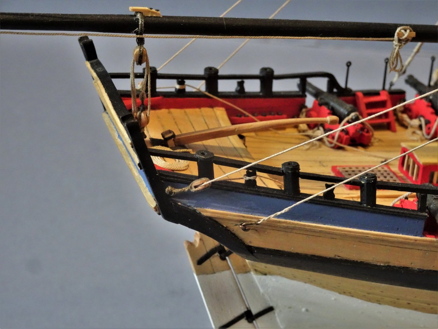
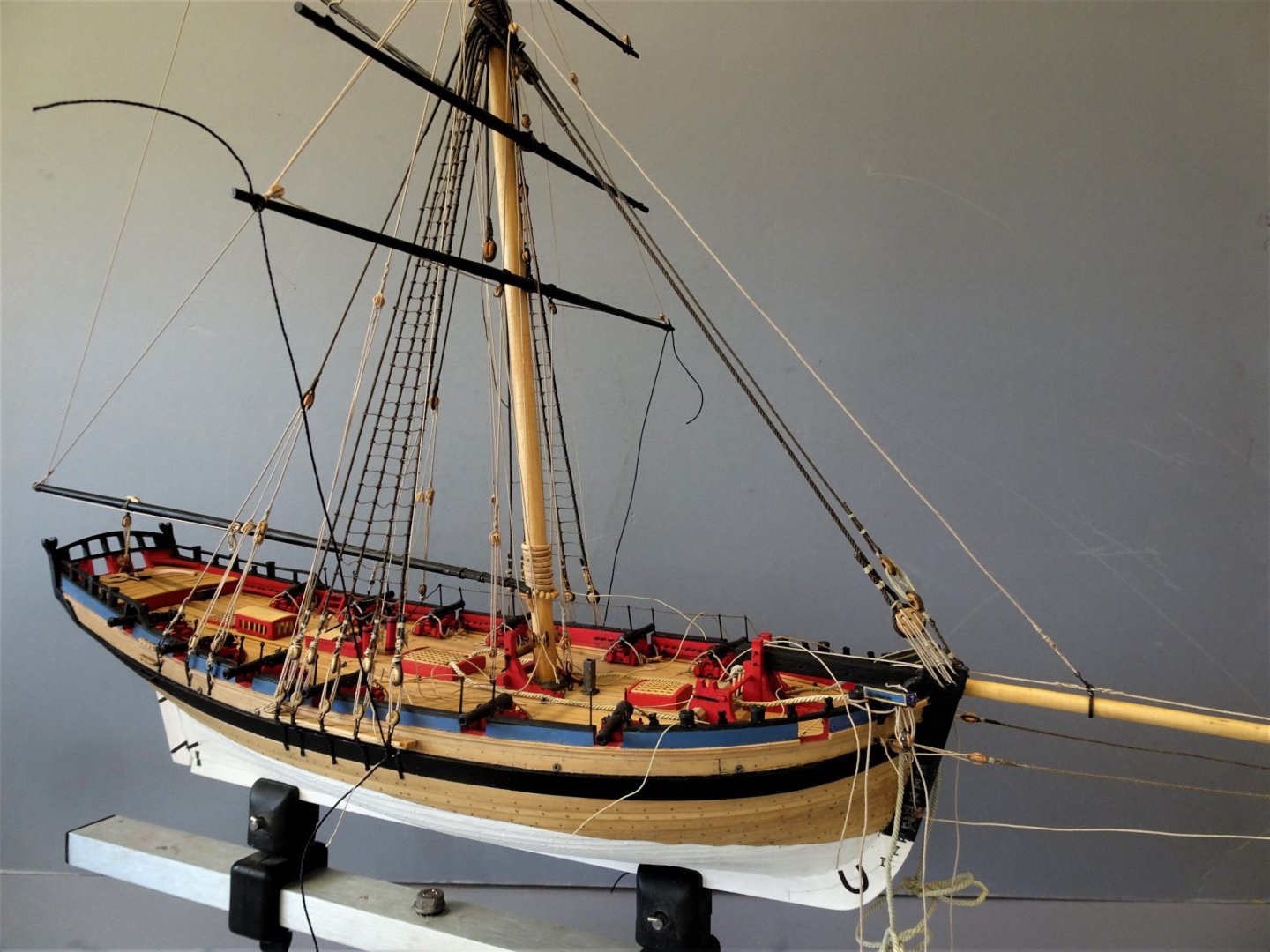
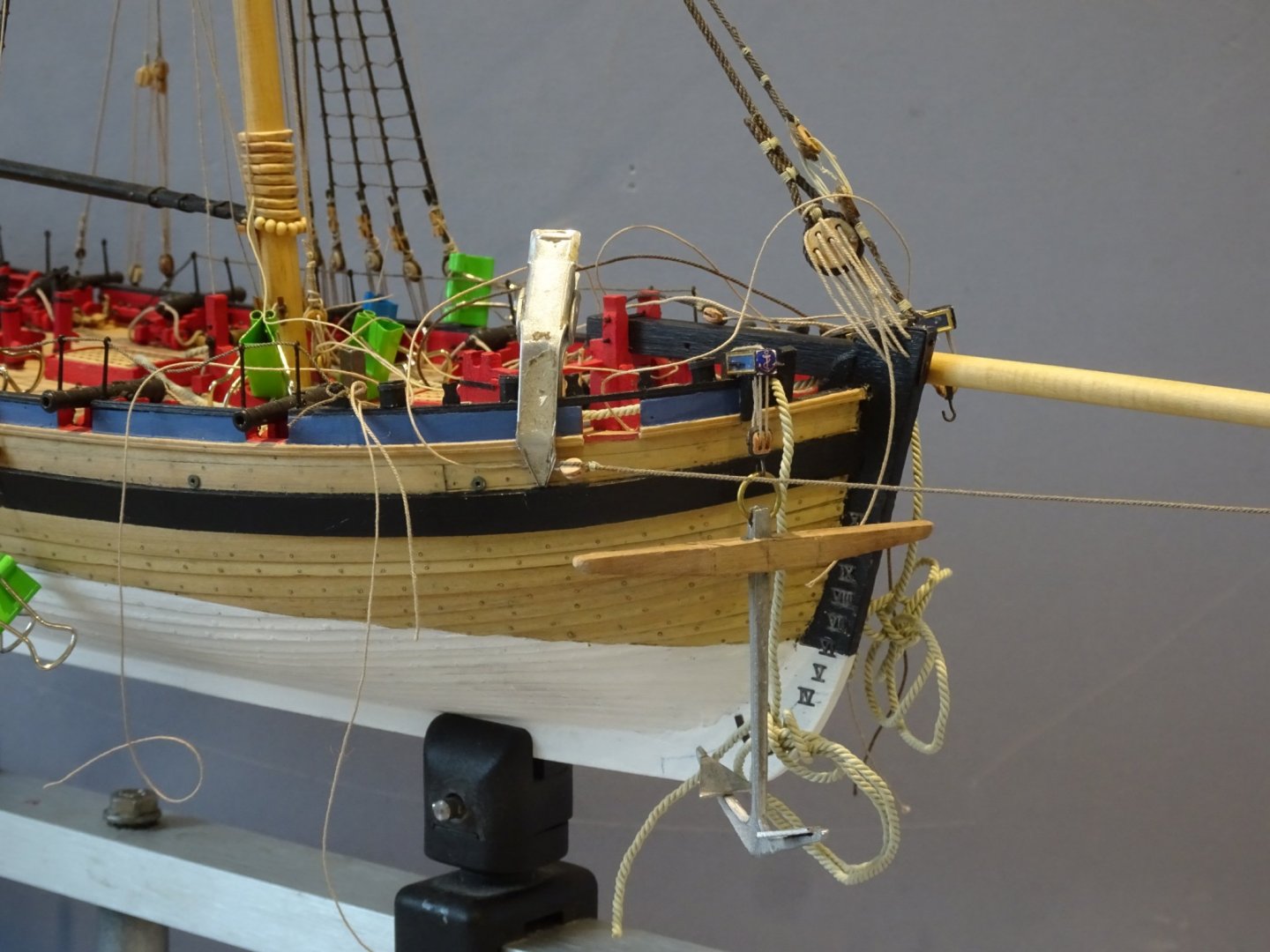
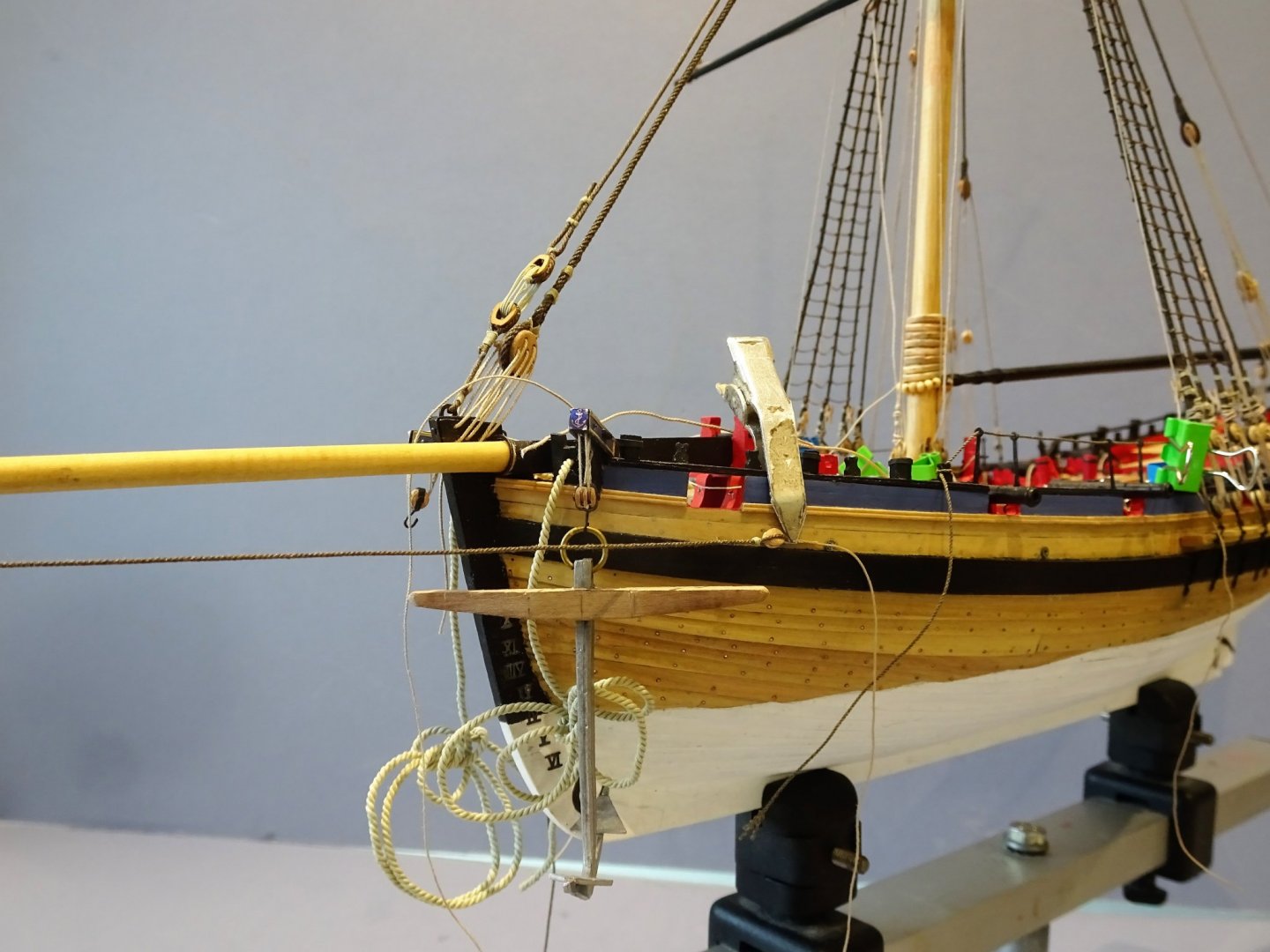
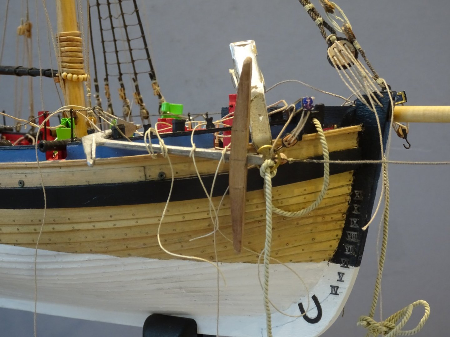
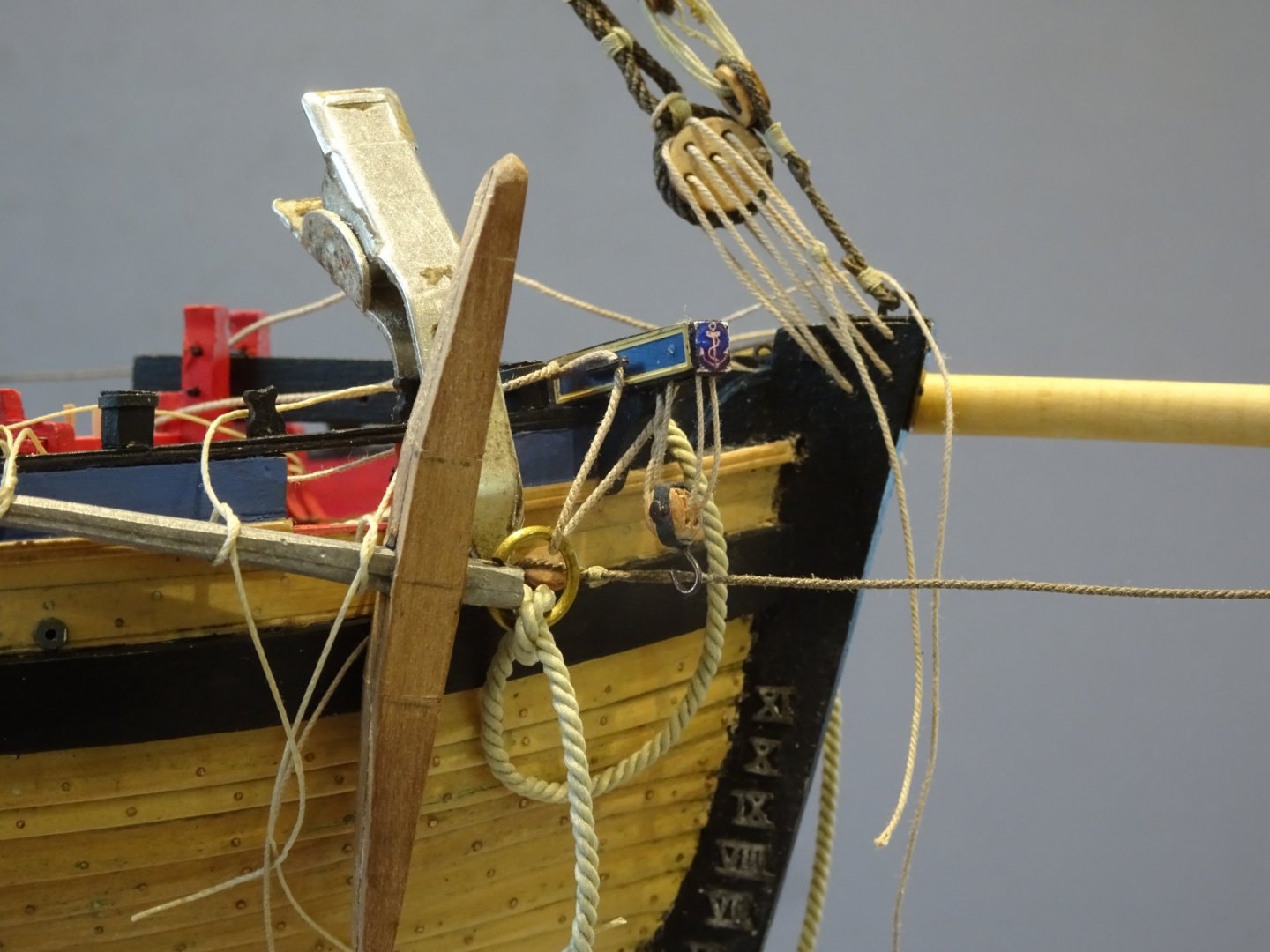
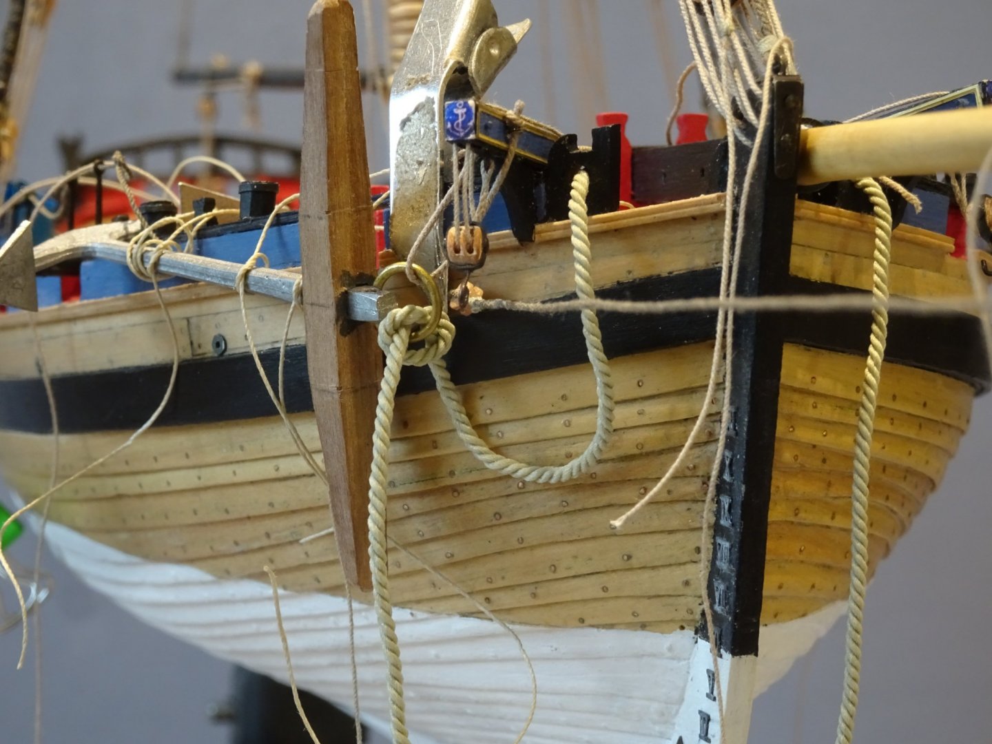
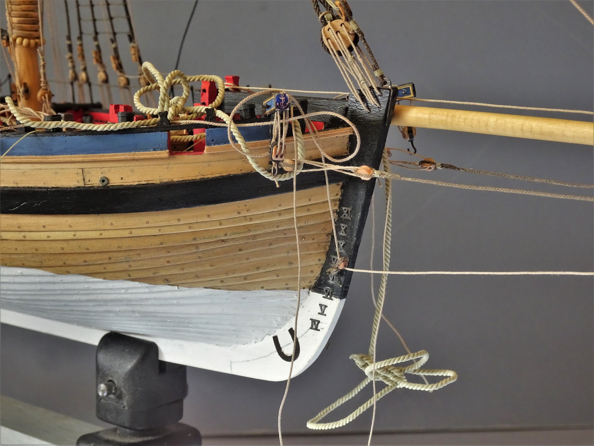
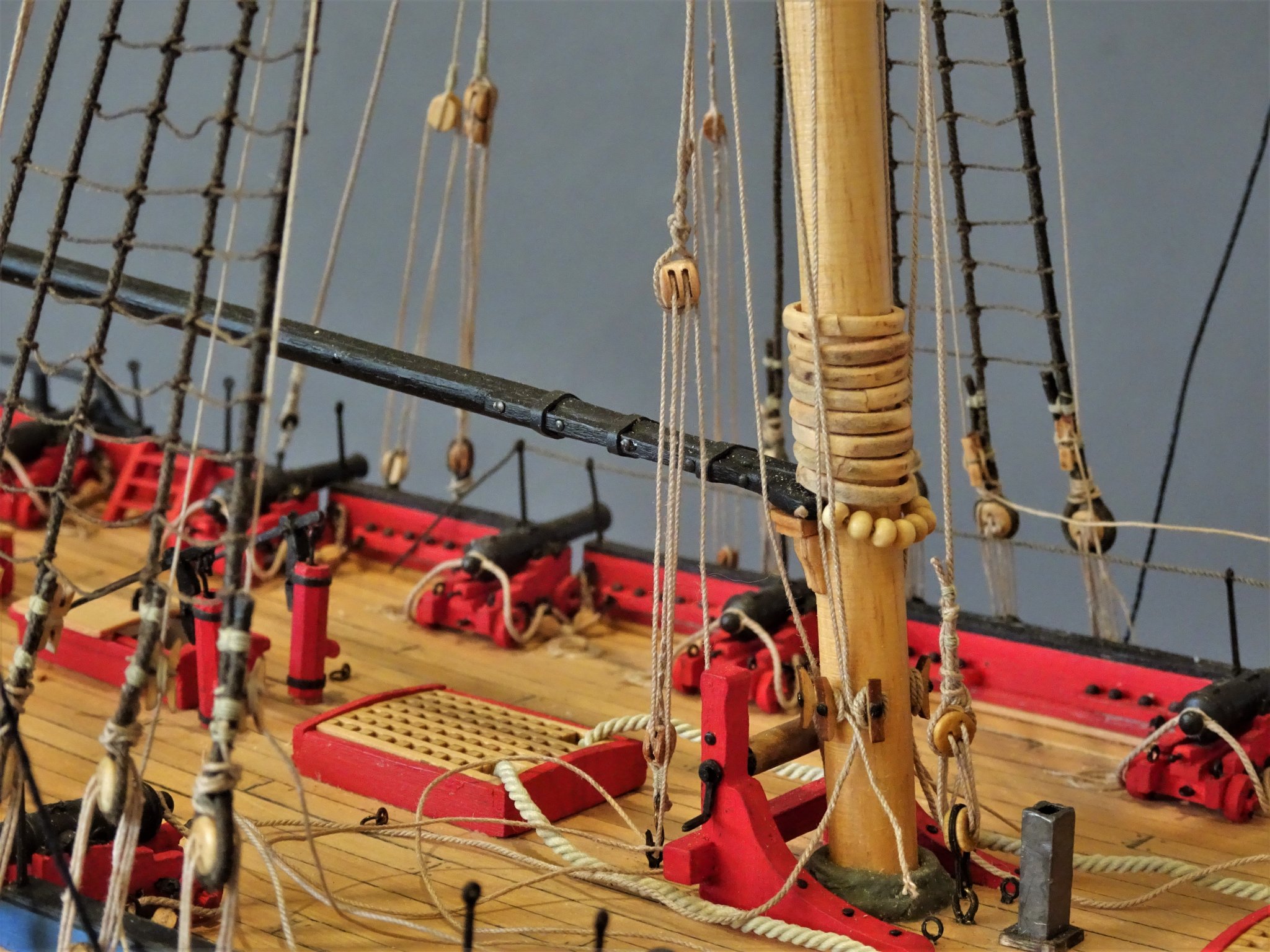
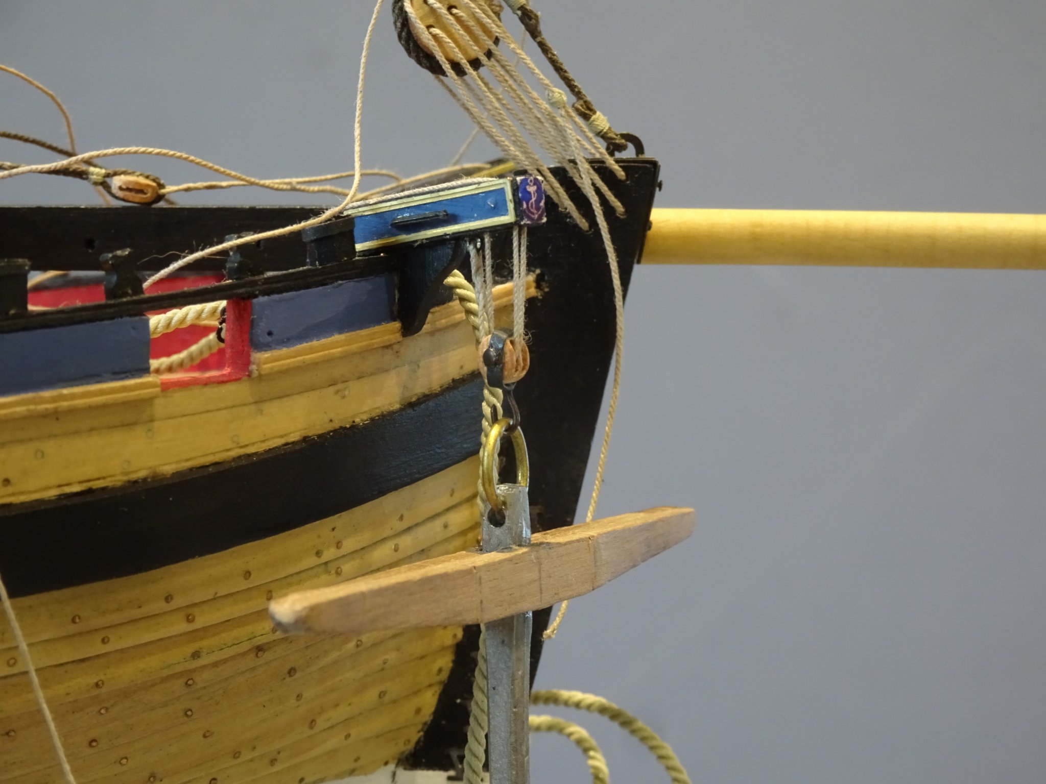
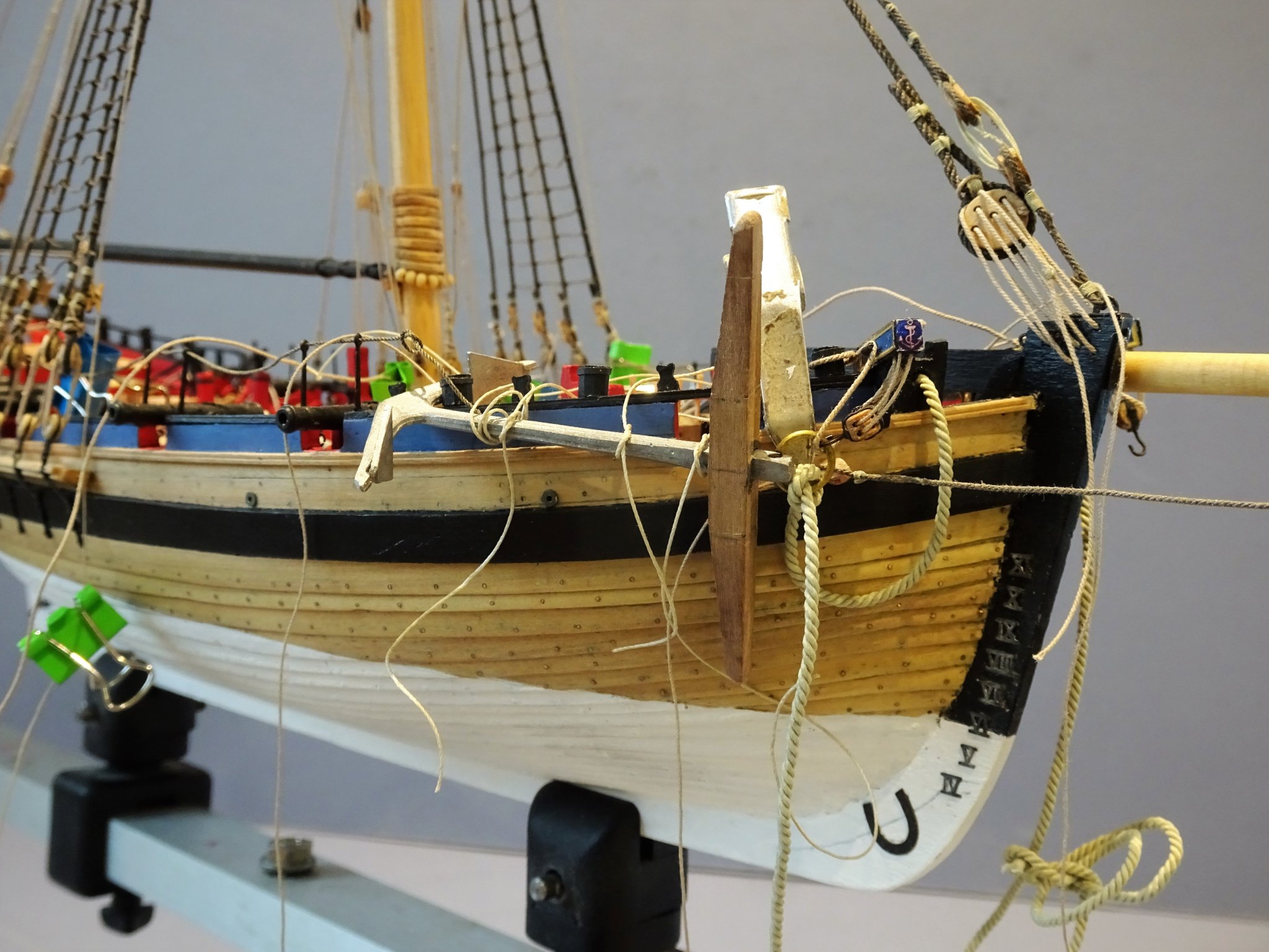
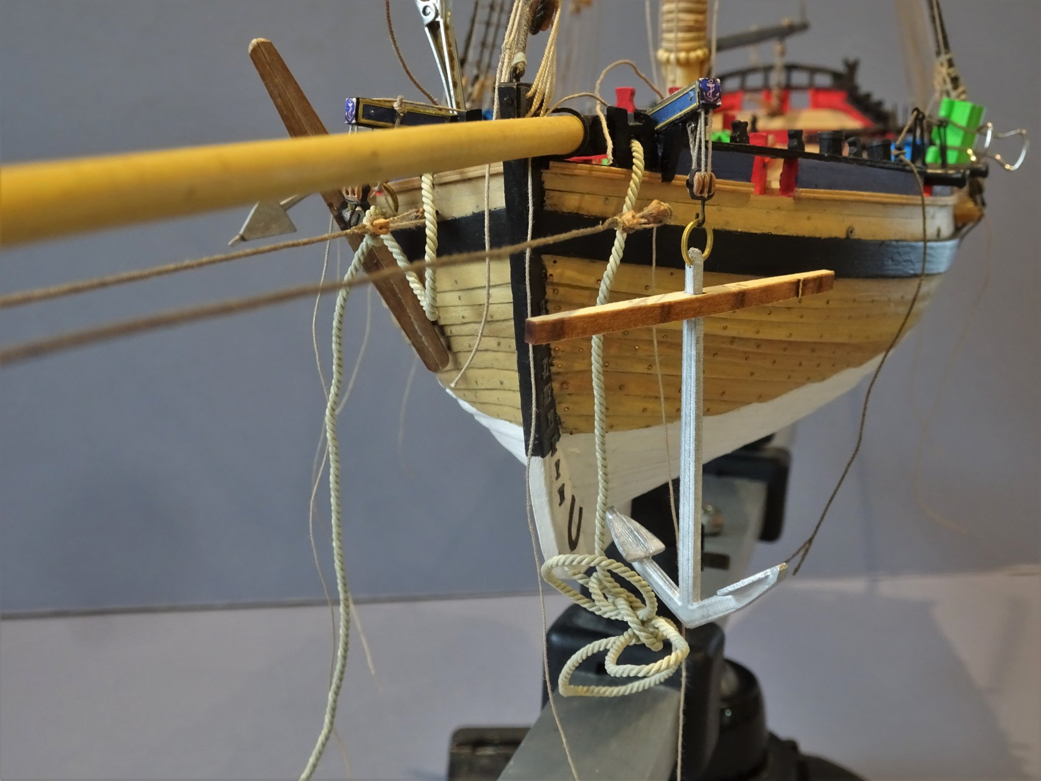
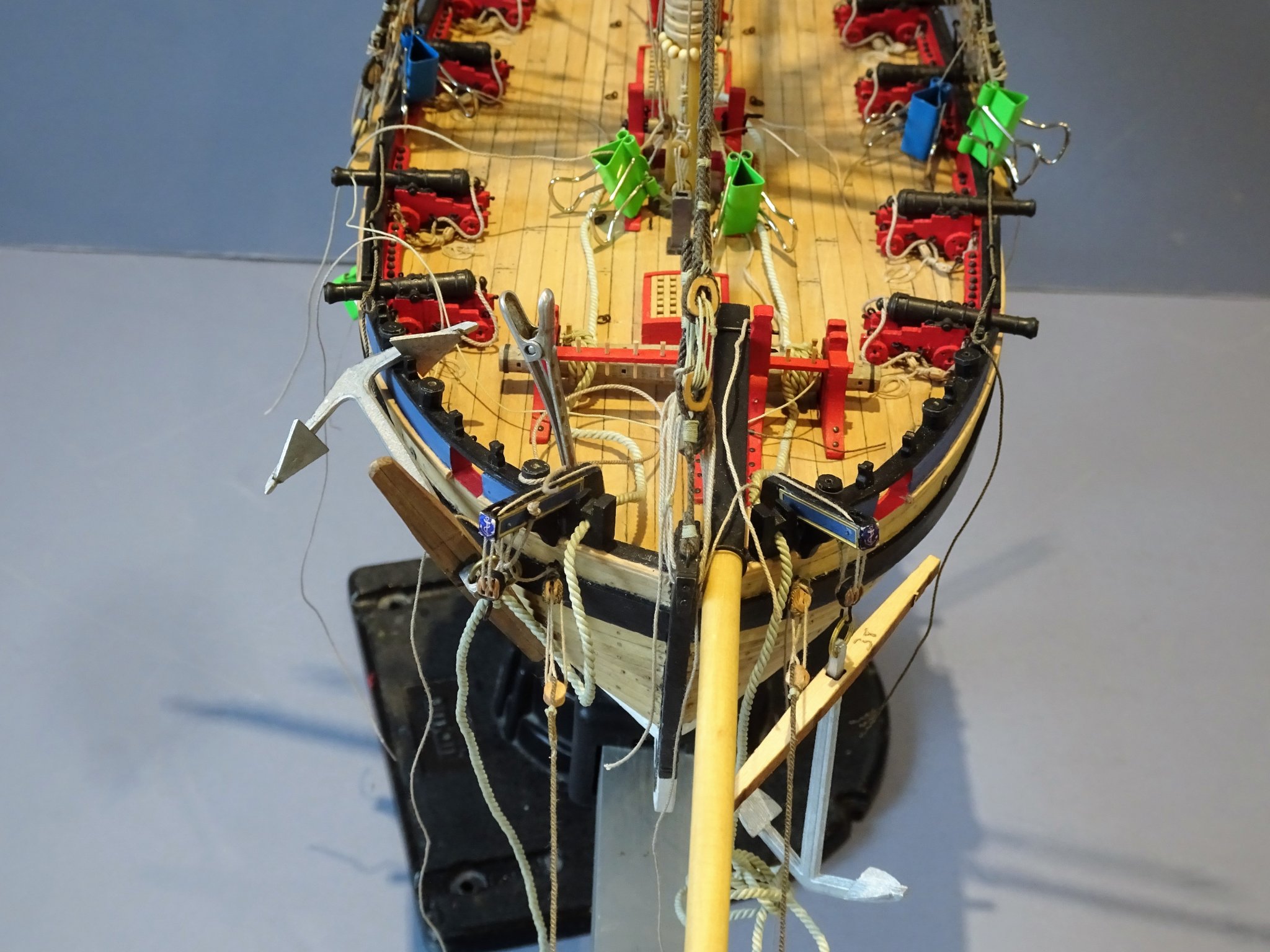
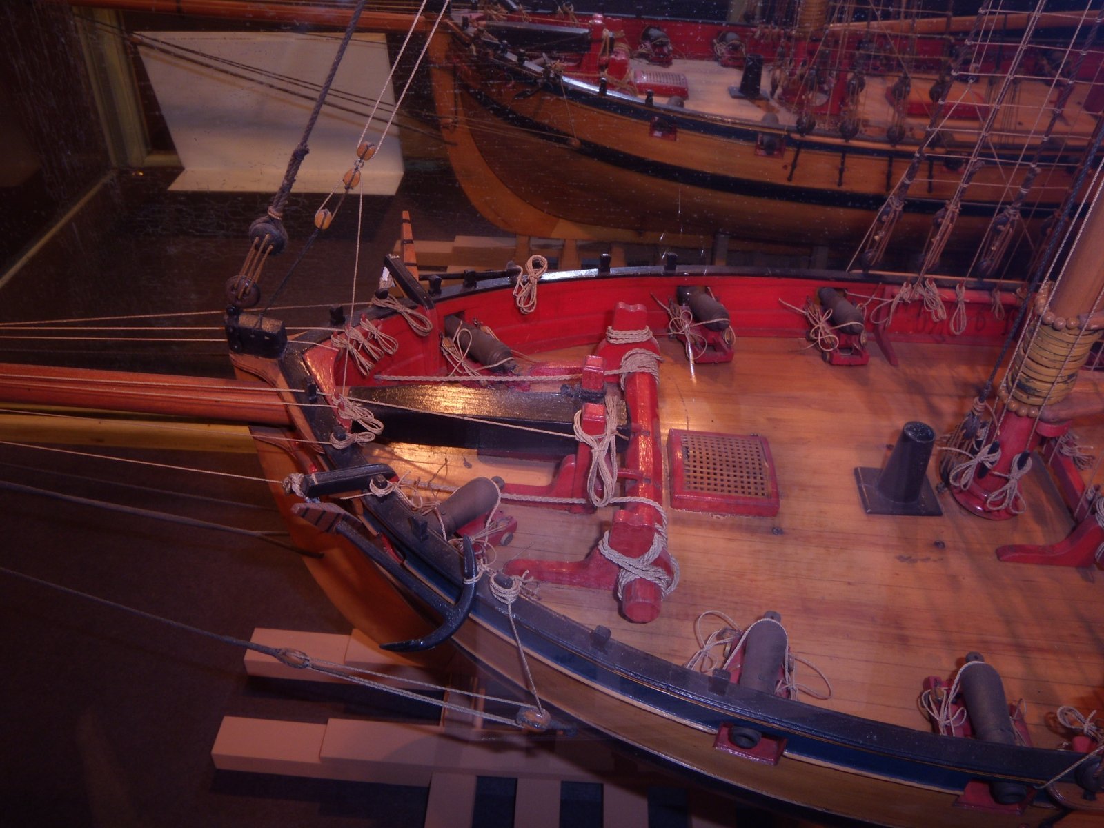
Post 75 I have diverted from rigging the Bowsprit to fit the Cat Block and tackle to the catheads so I can assess the relative position of the anchor gear in relation to the Bowsprit shrouds. Cat Block This is traditionally a substantial iron bound block with hook used to raise the anchor. 4615 Steel indicates a 12” block which scales to 4.8mm. I have gone with a 4mm block, 5mm looked just too large in relation to the Cathead. The ‘iron’ strapping is applied to the block and a hook inserted. Cat Tackle The tackle which runs between the Cathead sheaves and the block comprises 3” line. I have opted for Syren 0.3mm line. This is attached to an eyebolt beneath the Cathead, rove thro’ the sheaves and belayed inboard to a cleat on the Cathead upright. With the Shroud held in position as shown both in the Alert Book and the kit instructions, a problem is immediately highlighted. 4610 As can be seen with the Starboard anchor the whole arrangement sits behind the shroud and the anchor could not be worked without fouling. 4617 On the Port side the situation is the same except the angle of the shroud which is less due to the offset Bowsprit, is closer to the anchor. Cheerful model To confuse matters this shot of the Cheerful model does show the anchor tackle inside of the shroud lanyards, but the anchor is much smaller than on Alert, and looks to slip easily between shroud and stem. Moving onto a stowed anchor 4621 This is a mock-up with the anchor in the only stowed position available. For the purpose of the exercise the anchor is a Caldercraft version which is close to the kit anchor size. 4619 In this shot the anchor ring is still attached to the cat hook, but the stopper is also deployed. The Stopper, a heavier line, I used 0.63mm, is used to secure the anchor ring. It is knotted on one end, passes thro’ an eyebolt on the forward side of the Cathead, thro’ the anchor ring, thro’ the snatch block on the aft side of the Cathead and is secured to a timberhead. 4628 In this shot the Cat hook has been detached and the anchor ring is held by the stopper. This would be the normal arrangement once an anchor had been raised. 4626 With the anchor stowed the original position of the shroud connection just doesn’t work. The least impracticable position seems to be between the hawse hole and the Cathead bracket. Time to see how the re-positioned shrouds work out. 4630(2) The anchor cable running inside the shrouds is not an issue. 4633 This is the unprepped kit anchor which I will use but the stock will have to be replaced. These anchors do look large for the model, but they are of the given scale dimensions. With the re-positioned shroud the anchor can be displayed hanging from the Cat block. 4634(2) That Bowsprit is some spar, they should have named the cutter Narwhal. 4635 I think the shrouds look ok in this position, the Alert book drawings are not very helpful, but the photo’s of Hawke do appear to show the shrouds closer to the position above. 4637 I suppose I could have winged it and simply lashed the anchors to the rail as per the kit, but for those with eyes to see, letting go of the anchor would have been very interesting. B.E. 28/02/2020


.thumb.JPG.9e91b95fcc39f593abfeaa9edf024797.JPG)

.thumb.JPG.6a3ef88bec5428325cef28b136c8c9d4.JPG)


- 335 replies
-
- 20
-
-
- alert
- vanguard models
- (and 1 more)
-
I'm a confirmed bare stick man Derek, unless the model is set in a waterline diorama; but I've been there, done that, doubt I will re-visit the dio-sphere, once was enough for me.😃 Cheers, B.E.
-
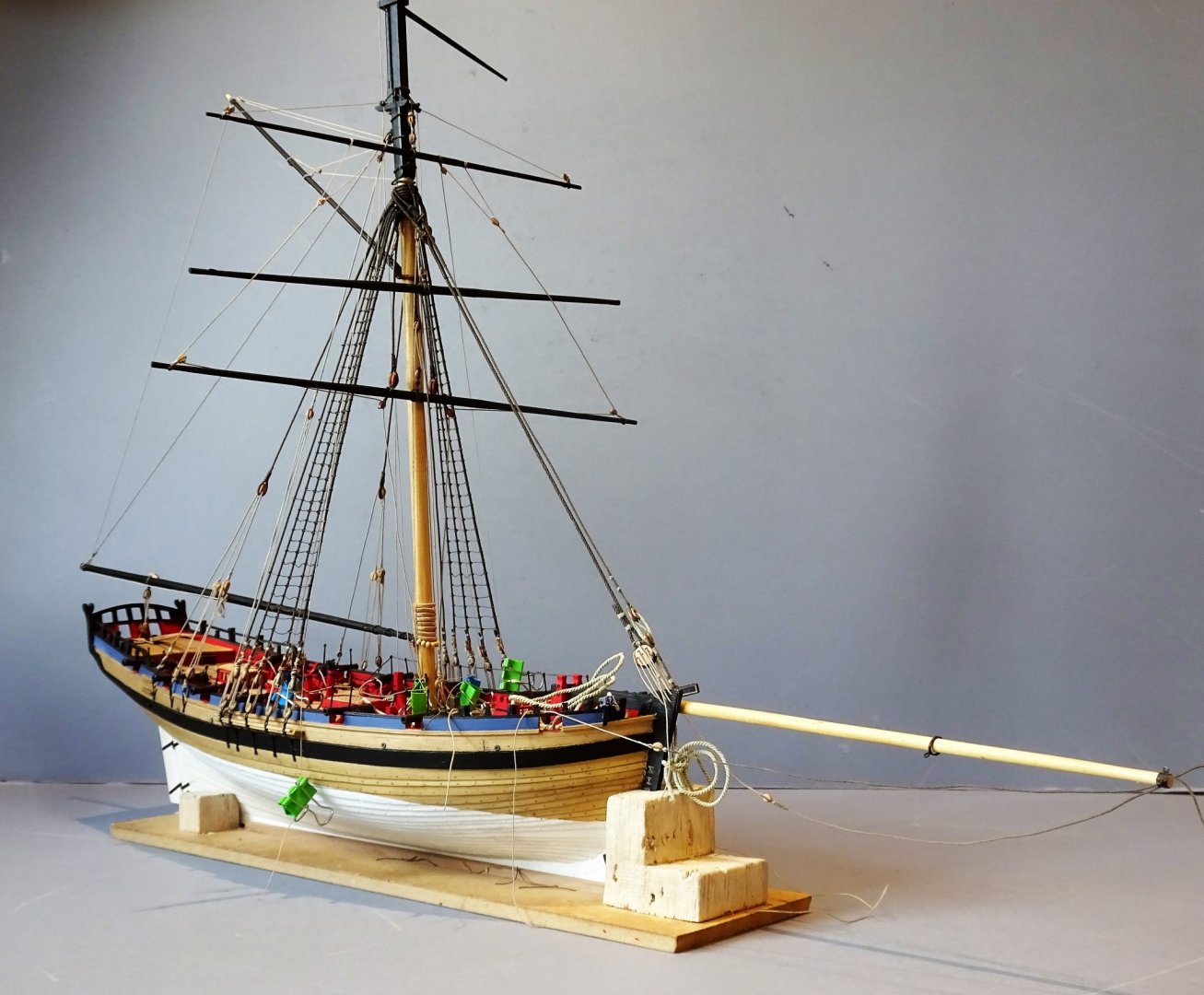
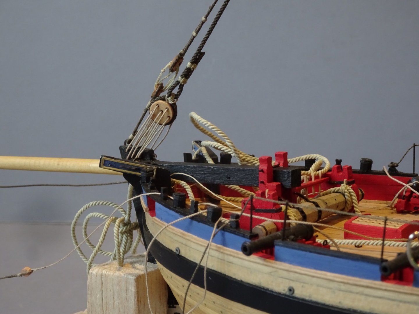
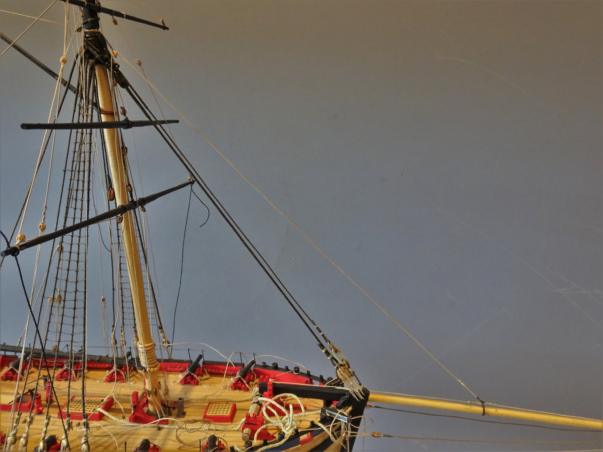
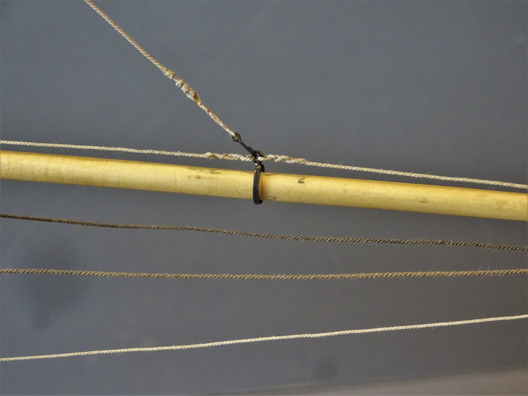
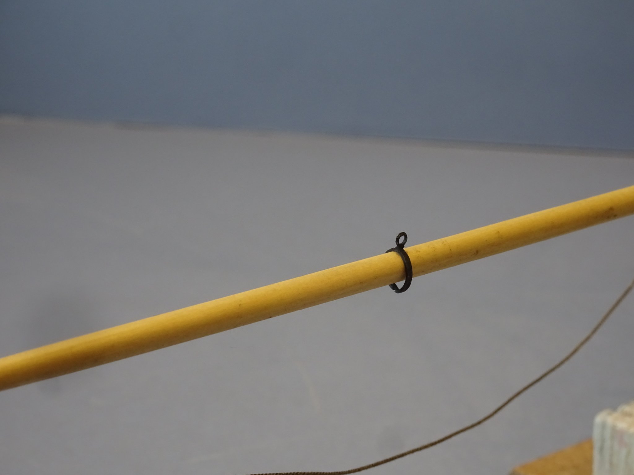
Post 74 Detailing the Bowsprit I have not wanted to fit the Bowsprit too early because it is an exceptionally long spar requiring a large turning area. 4605(2) So easy to knock as the model is turned about if the mind is concentrating on a particular task. The main detailing is at the outer end, but before much of it can be done the Bowsprit does need to be in place. A sheave needs to be cut a little way behind the cranse to take the traveller inhauler, but this is better done before the sprit is fitted. 4607 The sprit is put into place from aft and is secured by the two iron fids thro’ the bitts. It’s always better to be able to remove a spar should a ‘catastrophe at sea’ occur. The kit provides a brass etched Cranse iron and traveller ring in simplified form. These are referred to as the Bowsprit outer and inner rings in the kit instructions. I’m not too keen on the Cranse ring as it looks too thin in profile. 4604(2) I replaced it with heat shrink tubing fitted with eyebolts. The top eyebolt has a *treble block fitted to take the T’Gallant stay (centre) and the Topsail yard Braces port and Starboard. Once again, the Alert book has drawings at variance. H1 shows the T’gallant stay leading thro’ a single block attached to the cranse whereas the detail drawing H20 shows the treble block arrangement. *Whether a T’gallant stay should be fitted is also questionable. In the book narrative it is suggested that only when the T’gallant mast was fitted afore the masthead were Forestays, Backstays, and shrouds introduced. 3302a It is interesting to note that the Hawke model has neither stay or backstays fitted to the T’gallant. What can be seen here are only the Topsail braces and Bowlines leading to the Bowsprit end. The Kit Traveller ring is too tight to run the length of the bowsprit and is set I suspect at the position to rig the jib-sail. 4603 Again, it is rather thin in profile and I replaced it with a silver soldered version made from some 1mm wide brass strip. The ring atop the traveller has the jib inhauler attached and takes the hook for jib sail (Alert Book) Bowsprit shrouds For these I am using Syren 0.63mm ø line, and a 4mm block and hook tackle with 0.3mm line for the lanyards. 4605(3) The tackle end of the shrouds hook to an eyebolt in the bow above the wale, the kit has this placed just aft of the first port. 4606 At this point I need to at least temporarily rig the anchors to check that none of the tackle is fouled by the shrouds before I drill for the eyebolt attachment. Anchor rigging in the kit is a fairly simplified arrangement which obviates any issues which may present if the associated tackle such as the Cat Block and stoppers are added, and the anchors are displayed other than lashed atop the rail. I will return to the bowsprit once I have checked this out. B.E. 27/02/2020

.thumb.JPG.7fe2f42dfaa78e81e1380923b7ba8c04.JPG)
.thumb.JPG.c8e5759be1d779ee93738ab378be4f83.JPG)
.thumb.JPG.69377dd6a3aaec911058cbed99b2f92f.JPG)

- 335 replies
-
- 20
-
-
- alert
- vanguard models
- (and 1 more)
.JPG.39d086ceb12bba2b7fbfb853df6cb40c.JPG)


.JPG.e8b3c276f93e24a1ef9f9343c2c94026.JPG)
.JPG.55bf8e5731a2eebd6df8734fc3dcab58.JPG)
.JPG.df02c19b002b293c2a50db5b58a5faaa.JPG)
.JPG.f2cdc7482e0c672257a48f8cb83bcb7c.JPG)

.JPG.8e8ad54125326fdc870c481392c11abc.JPG)
.JPG.537b61572c2c731b9f6a48bf22046b71.JPG)

.JPG.0c63701f3f1234e70c62b3332ddb08ee.JPG)
_LI.jpg.6e8a64594ca4cc7e3d62319dbe35961d.jpg)
.JPG.6050f30277676a93dc25276ca18c348b.JPG)

_LI.jpg.b19bd613edcb59eb309061013ae413ab.jpg)


.JPG.96285aca1aacf3b46781544a8458806e.JPG)
.JPG.4f4eae1b9366d95f0fc77306cc150387.JPG)

.JPG.1519e80011c993e02e15022af2221bb6.JPG)
.JPG.6d181b5547d260d7ef6345f8a98af802.JPG)
.JPG.650109ac3165cee9bc8bef691b312f93.JPG)