
HOLIDAY DONATION DRIVE - SUPPORT MSW - DO YOUR PART TO KEEP THIS GREAT FORUM GOING! (Only 20 donations so far - C'mon guys!)
×
.JPG.ca33079f5815b861e67b9c2cccd37982.JPG)

Blue Ensign
-
Posts
4,564 -
Joined
-
Last visited
Content Type
Profiles
Forums
Gallery
Events
Everything posted by Blue Ensign
-
 I masked the paintwork off to apply the poly. B.E.
 -
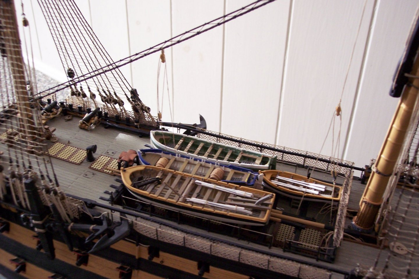
This is the arrangement I went with based on published sources. This shot of Victory shows the 18' cutter to the rear, the Pinnace ahead of it, and the Admirals Barge to the right. The empty chocks are for the Launch which is displayed along the dockside. B.E.
-
Impressive package, that building frame is a work of art in its own right. Be interesting to see how things progress. B.E.
-
Great progress Glenn, your Hull is a thing of beauty, very nice work. It’s nice to have a facsimile of the original plans of the models we make, the NMM do produce very nice copies. B.E.
- 778 replies
-
- 4
-

-
- cheerful
- Syren Ship Model Company
- (and 1 more)
-
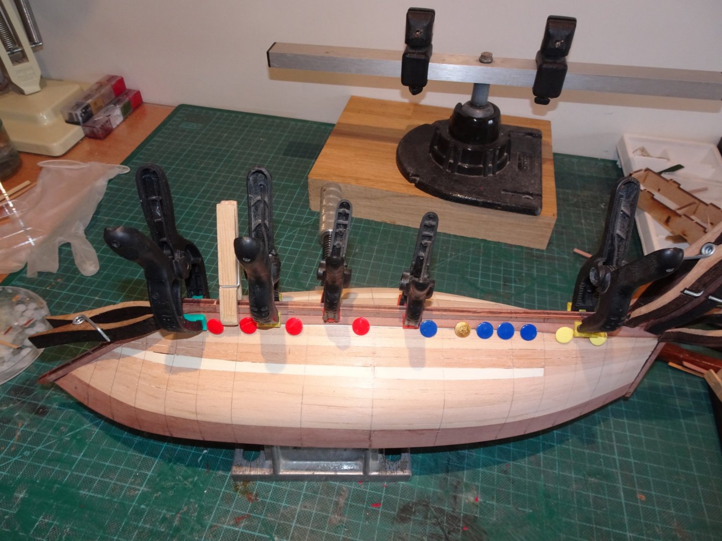
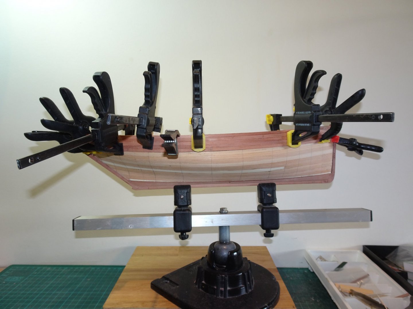
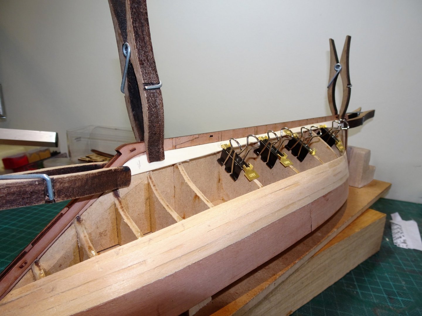
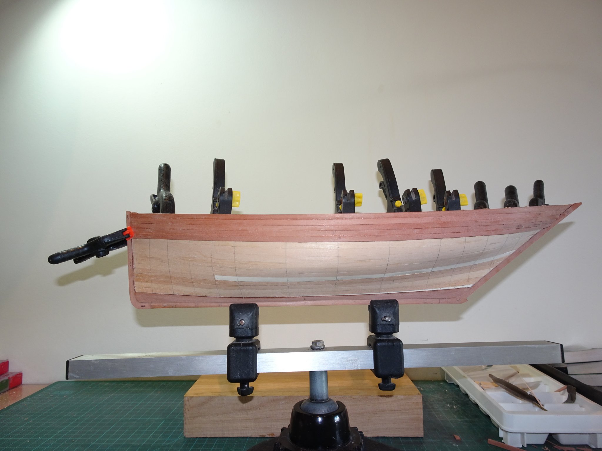
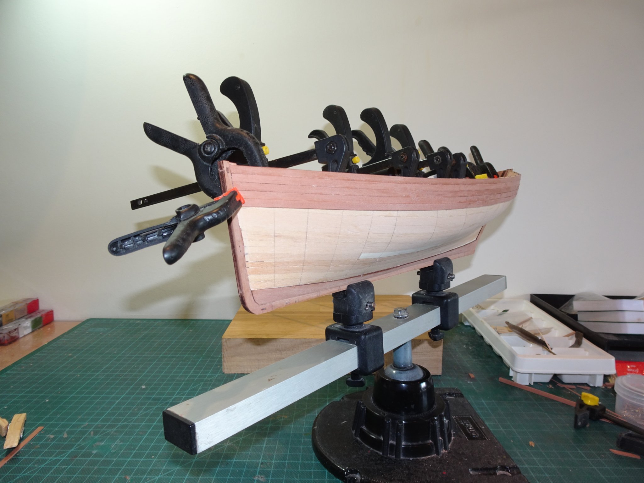
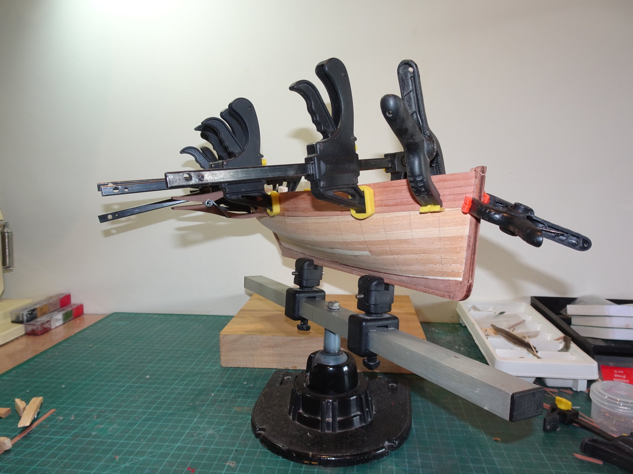
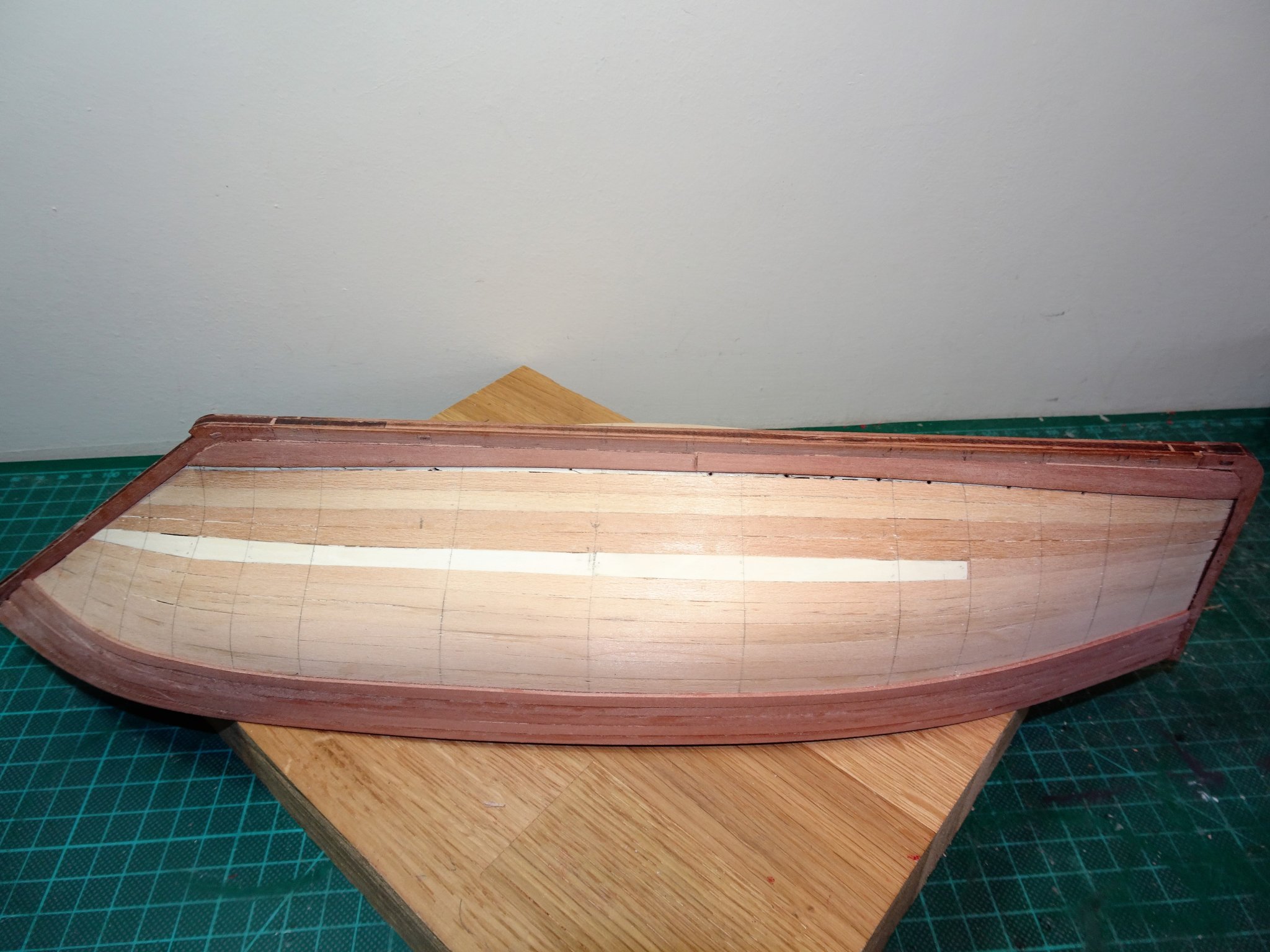
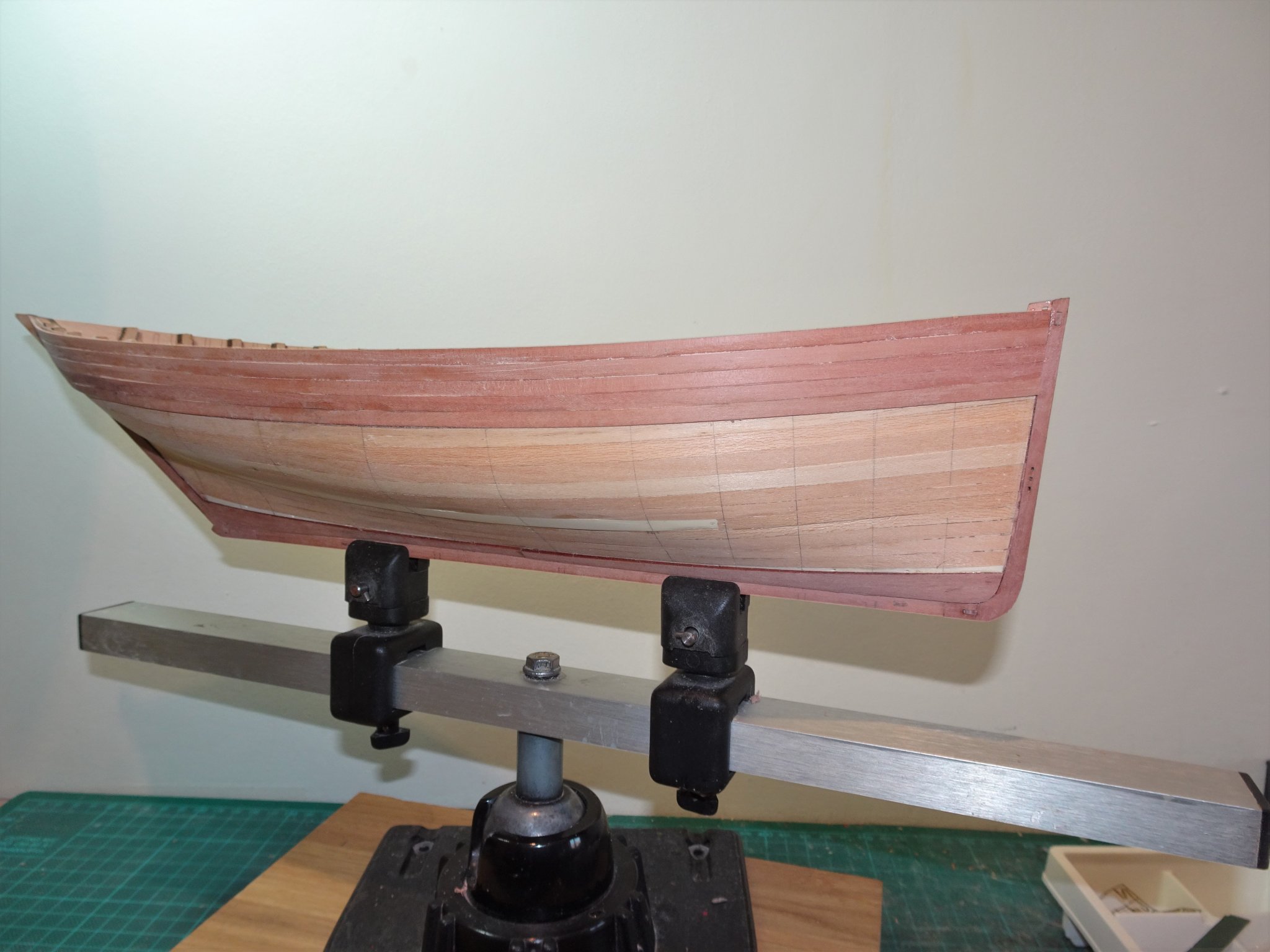
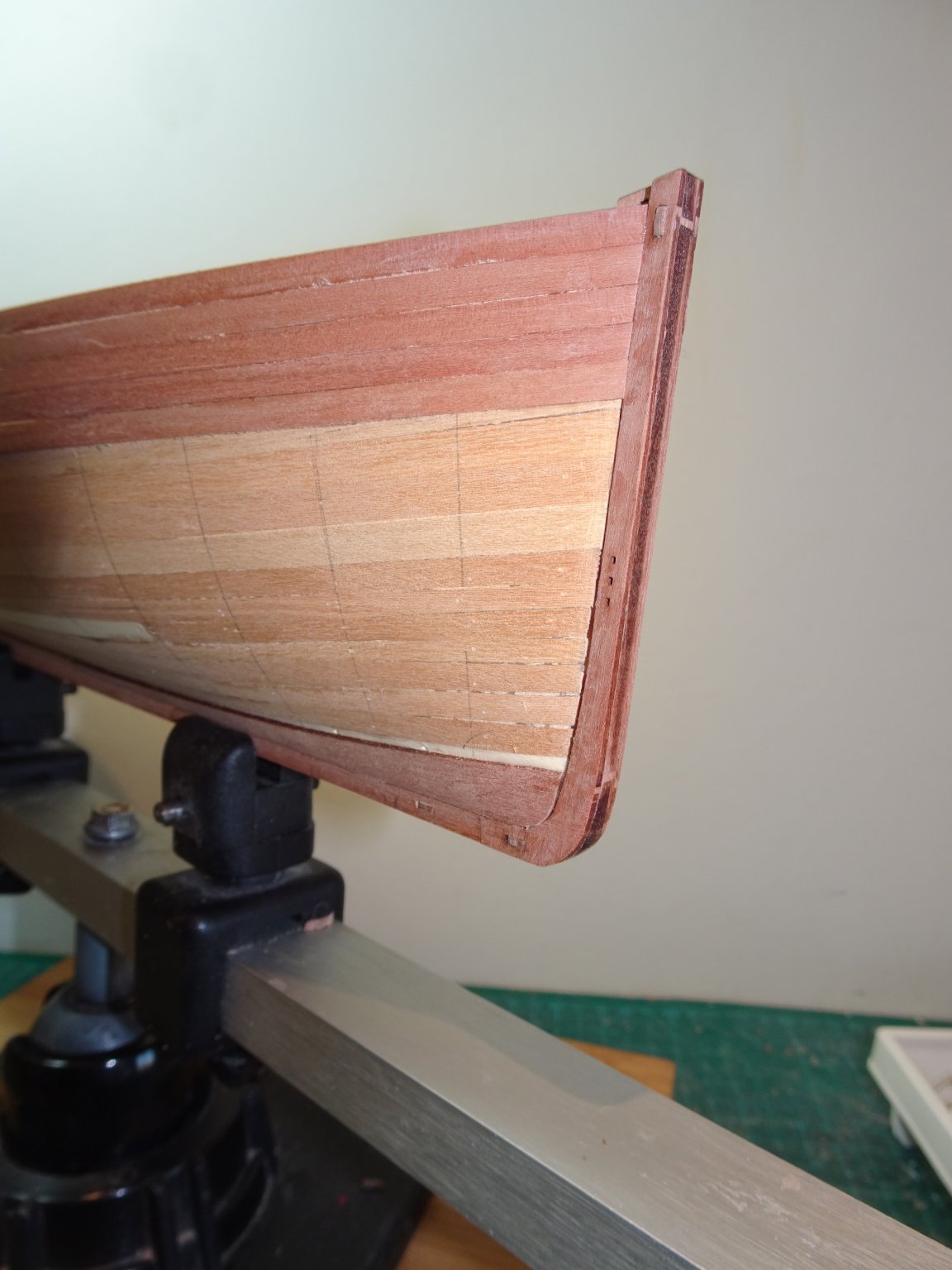
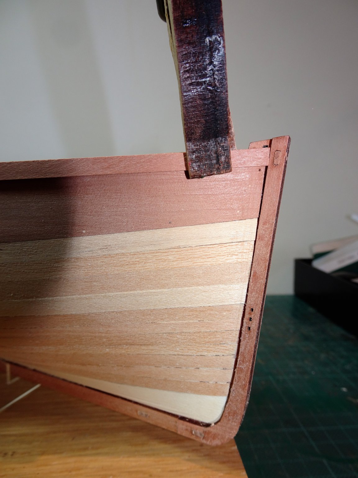
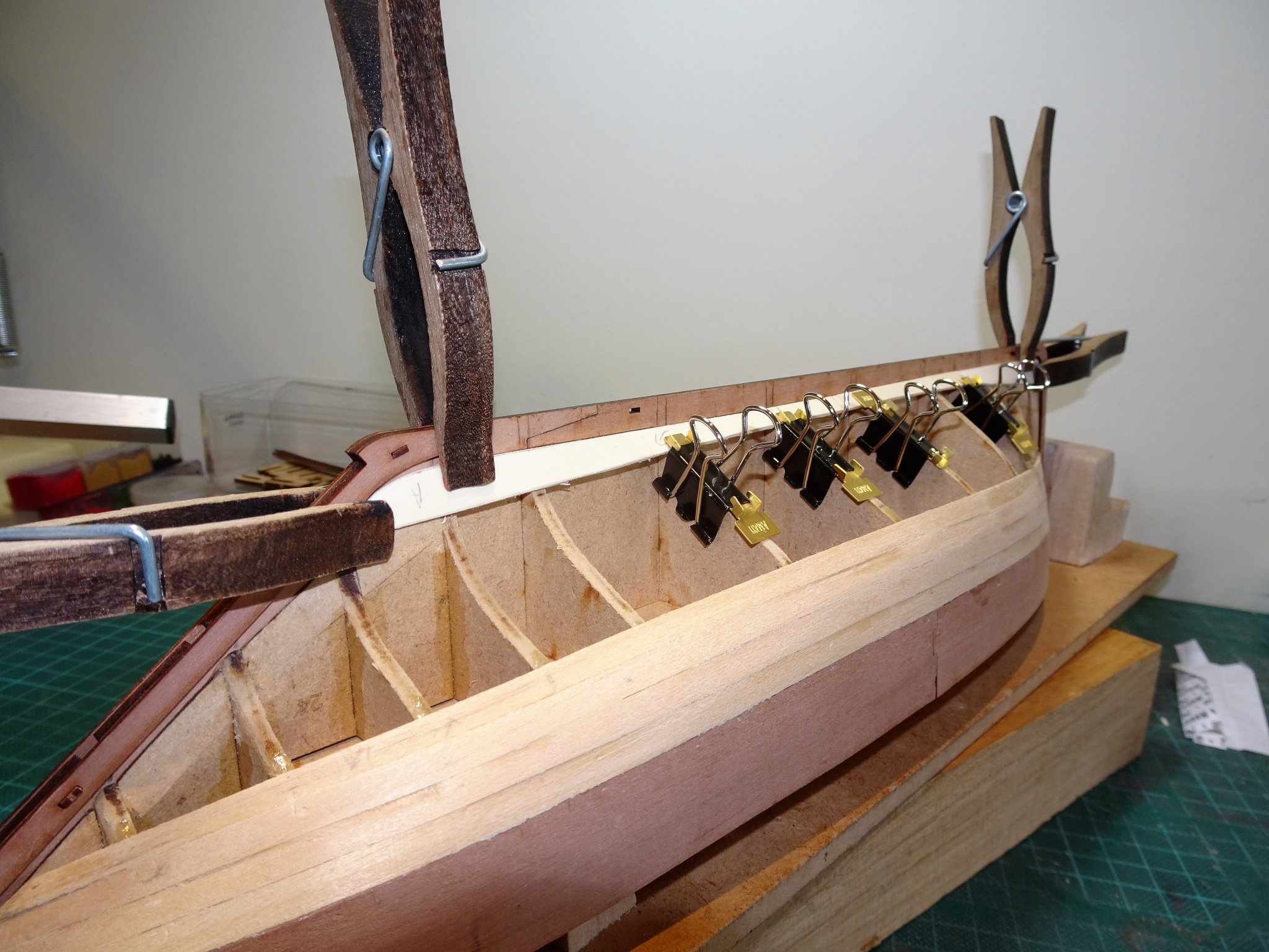
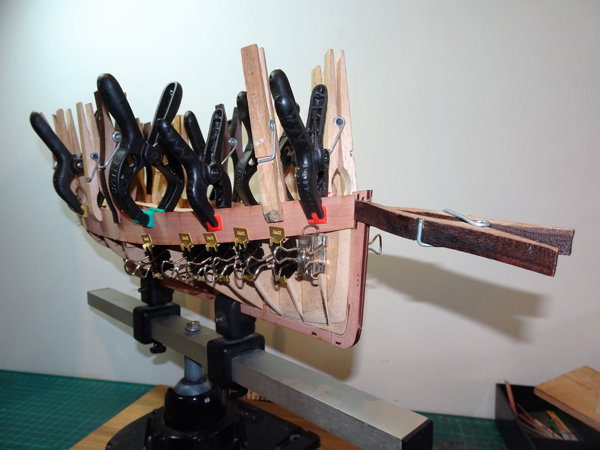
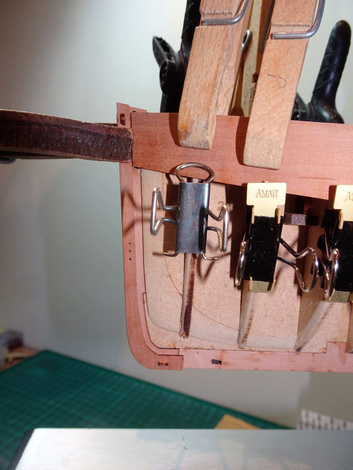
Post 6. Second Planking. This begins with the pre cut Garboard planks, another excellent idea from Chris.👍 Head scratching over the Garboard shape and extent of its length is something that happens to a lot of modellers, me included, and I’m grateful for its inclusion. 6959 The supplied patterns are a perfect fit requiring only a slight bevel to the keel edge. I also heat induced a slight twist to the plank to suit the hull shape along the keel. 6938 I used pva to fix these planks as I limit my use of ca to the minimum. Moving onto the Pearwood planking. It may be that Chris has already amended the manual but for those following it literally there is a narrative error in instruction 14. That may cause confusion. 6902 References to the planking starting at the main wale position markings, which are shown on the gunport patterns, obviously relates to another model. The planking I assume starts along the top line of the bulwark pattern as with the Fifie model, and this is where I will start. I sorted thro’ the stock of Pearwood strip and picked out the best strips matched for uniformity and colour. I am primarily concerned with the planking down to the waterline about twelve strakes each side, as this will be simply sealed with wipe-on-poly. In the end I decided to go with the supplied planking for my Cutter Alert Kit (which I didn’t use) and which has overall more consistent milling and a richer colour tone. 6944 The first three strakes down were fitted without taper, the Pearwood strip easily followed the sheer line, getting a close fit at the stem and stern posts is the main consideration. 6942 Below the second strake and my normal peg clamps don’t work, and the third strake is the limit of my modified peg clamps. 6945 The fourth strake down required a little edge bending towards the stern, but no tapering, and thanks to the large hatchway there is purchase to use the larger clamps. 6950 The fifth plank down requires both edge bend and taper at the stern. 6956 Beyond this point the option of clamps is removed so a degree of ca will be introduced at the bow and stern. 6955 The pre-formed Garboard plank can be seen running along the keel line. 6953 6965 Pre-fitting I do fine down the ends of the planks at the bow to reduce final sanding. 6960 With five strakes completed I will stop here and use the tick trip method to work out the remaining planking requirements before I continue. B.E. 02.09/2020
.thumb.JPG.6199d47bafbd3629e154db2d6285455e.JPG)


- 261 replies
-
- 19
-
-
- muirneag
- vanguard models
- (and 2 more)
-
My only experience thus far is with my Fifie build. I only used two coats of wipe-on. This is the effect, the richness of the Pearwood is brought out, there is a very slight natural sheen but it is enhanced here by the artificial light used for the photo. Hope this helps. B.E.

-
Thank you PJG, I do intend to include the net platforms, nets, and floats in the hold, which is as much as can be done with this type of pob build. You've got a better chance of making herring at 1:32 scale, around 12mm in length, and their torpedo shape make for a simple design. I will be interested to see how they turn out. Regards, B.E.
- 261 replies
-
- 2
-
-
- muirneag
- vanguard models
- (and 2 more)
-
Thank you Thomas, the outer planking is Pearwood including the bulwark pattern because the inboard side is on show. I think the richness of Pearwood really suits this type of vessel, particularly once treated with a wipe-on-poly. Cherry would also suit it very well. 🙂 B.E.
- 261 replies
-
- 4
-
-
- muirneag
- vanguard models
- (and 2 more)
-
I understand that Fake relates to ropes on a deck, whereas Flake relates to the laying out of a chain anchor for inspection. According to the Oxford Companion to Ships and the Sea Flake is also an old maritime name for a cradle or stage suspended over a ships side. Learn something new everyday 🙂 B.E.
-
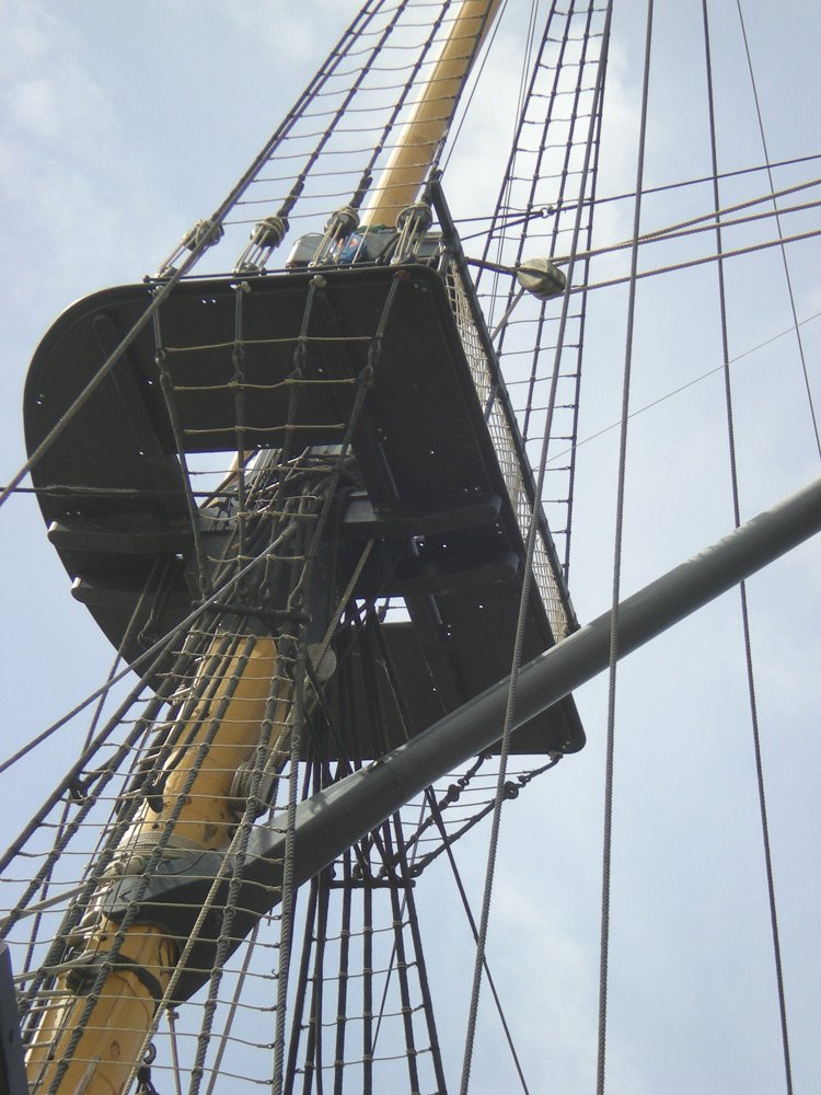
Hi Ian, Looking at your splendid Victory, it didn't strike me that the Gaff was slung too low, but things can look different from different angles. Here's a possible get out of jail card. You can see here that the Gaff is slung below the Catharpins. Personally I would leave things as is, or at least think very long and hard about re-visiting at this stage. Regards, B.E.
.jpg.591ba5712df23ce1328d3200f76a102a.jpg)
-
Very nicely done Glenn, cutters make such great models. Love the colour combination of dark and light woods below and above the wale. Some useful ‘how to’ tips in the narrative.👍 that other forums loss is certainly MSW’s gain. Regards, B.E.
- 55 replies
-
- 1
-
-
- lady nelson
- victory models
- (and 2 more)
-
Looking good, Cheerful is one of my favourite models, and yours is progressing nicely. 👍 Regards, B.E.
- 54 replies
-
- 1
-
-
- cheerful
- Syren Ship Model Company
- (and 1 more)
-
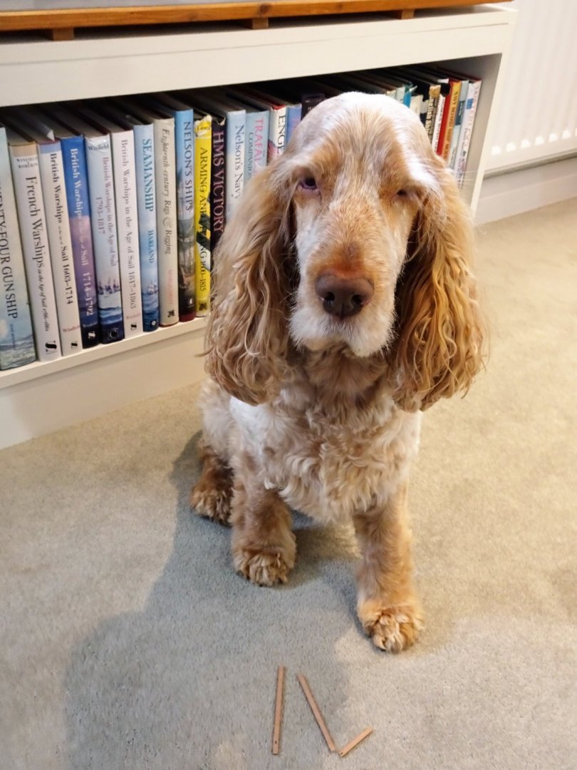
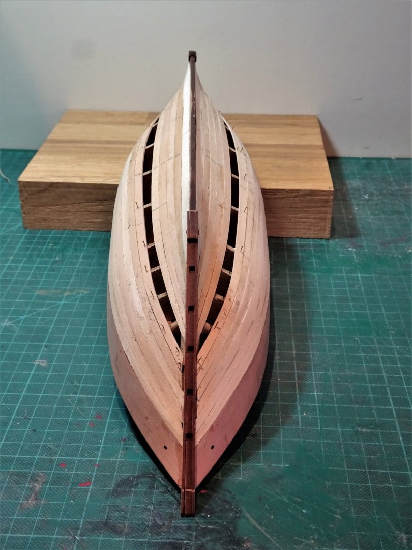
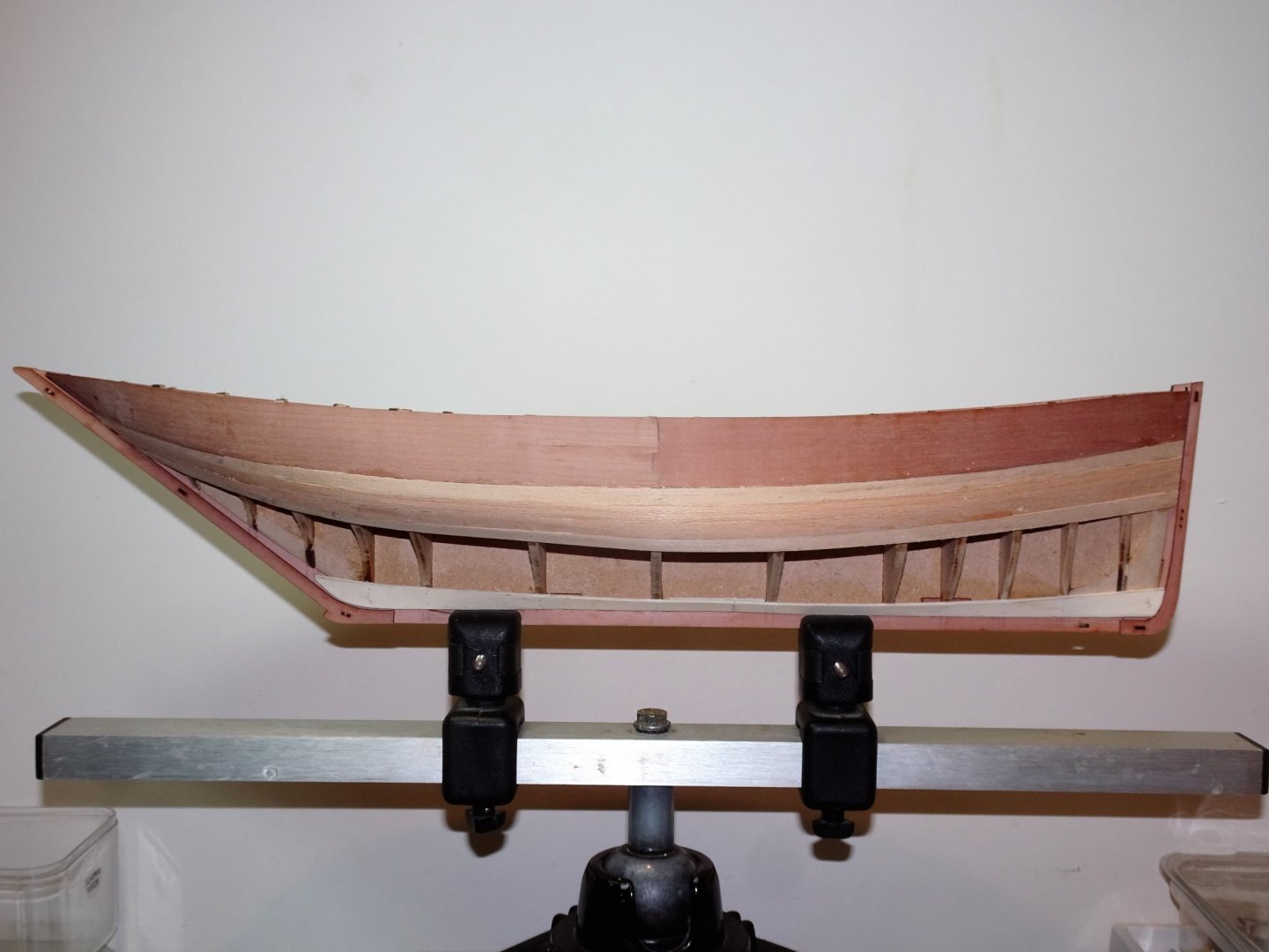
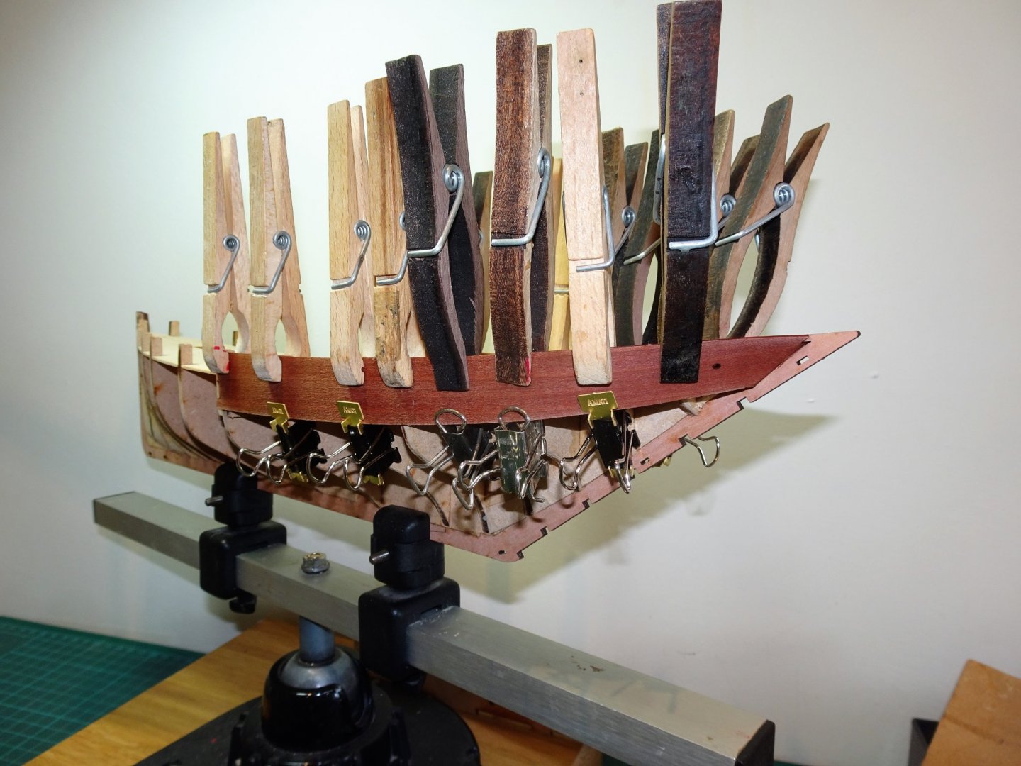
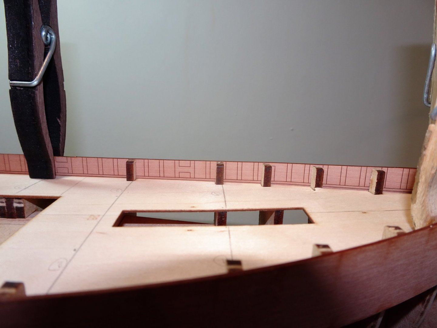
Thank you Bob and Rusty, and to those who have looked in and 'liked' Post 5 Preparing for second planking With sanding of the first planking completed the stem piece and keel and stern pieces can be added. I do rather like this method devised by Chris of having facing pieces in a nice wood which also provide a sort of rabbet for the second planking. Slight set back as my assistant decided to practice some abstract canine carpentry on one of the keel strips that had fallen from my bench. 6976 Fortunately, a strip of Pearwood from the part retaining fret was available to make a replacement. So here she is ready for the second planking, seems longer than the mere nine days since I actively started the project. 6920 Careful sanding down of the first layer around the bow and stern has allowed the ‘rabbets’ to provide sufficient edge to contain the second planking. 6925(2) A first opportunity to compare the Fifie and Zulu side by side. 6908(2) Sleeker than the Fifie and a tad longer, awaiting her transformation into a Swan. 6911(2) They will make a fine complimentary pair representing the apex of the Scottish fishing industry of the early 20th century. B.E. 29/08/20
.thumb.JPG.f8bd903bc23e7399d0c8b97936399ad4.JPG)
.thumb.JPG.1fb436272970dd6cc620624fbfdf8325.JPG)

.thumb.JPG.d34255c776f5fd5ebaf8e085b095229f.JPG)
- 261 replies
-
- 20
-
-
- muirneag
- vanguard models
- (and 2 more)
-
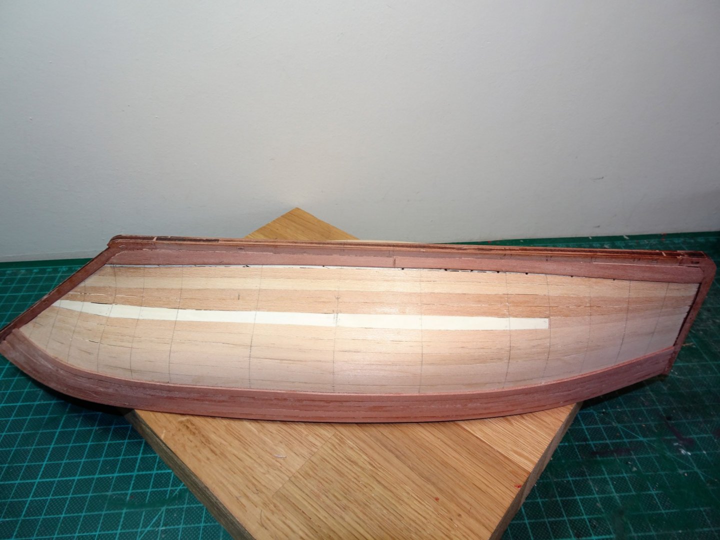
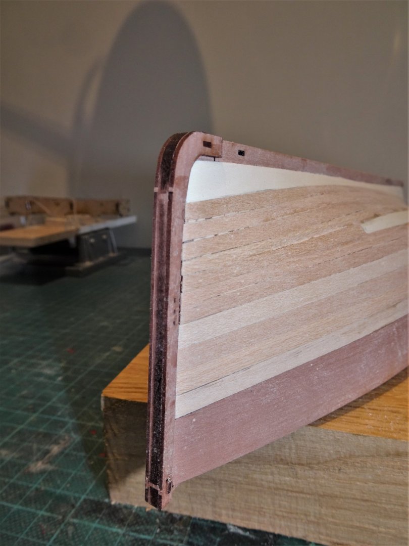
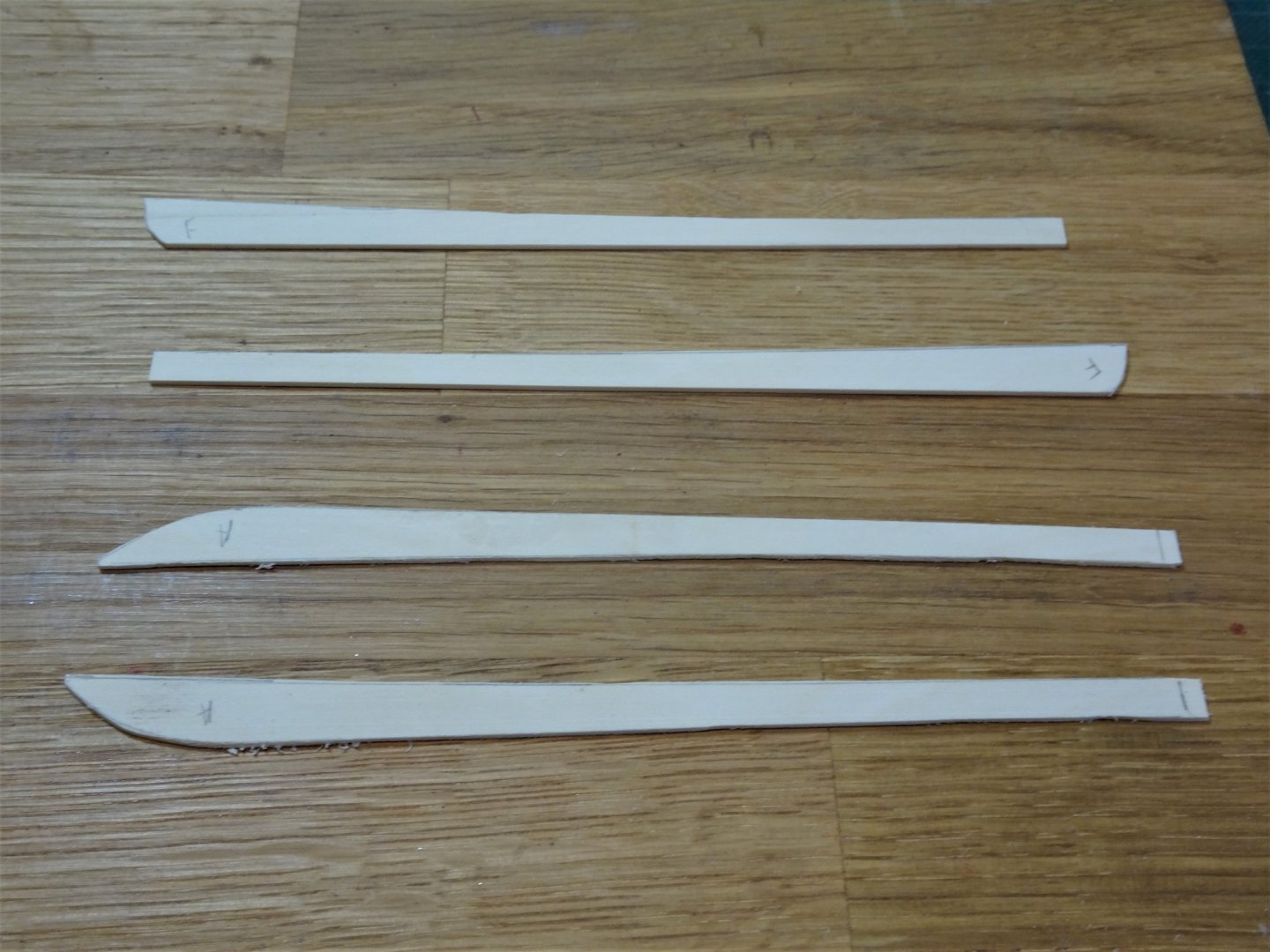
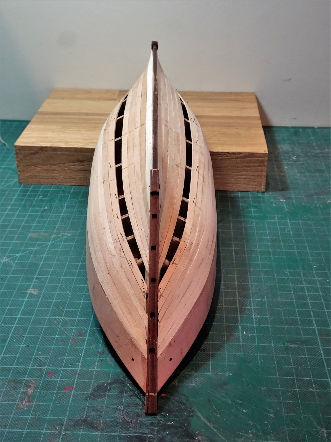
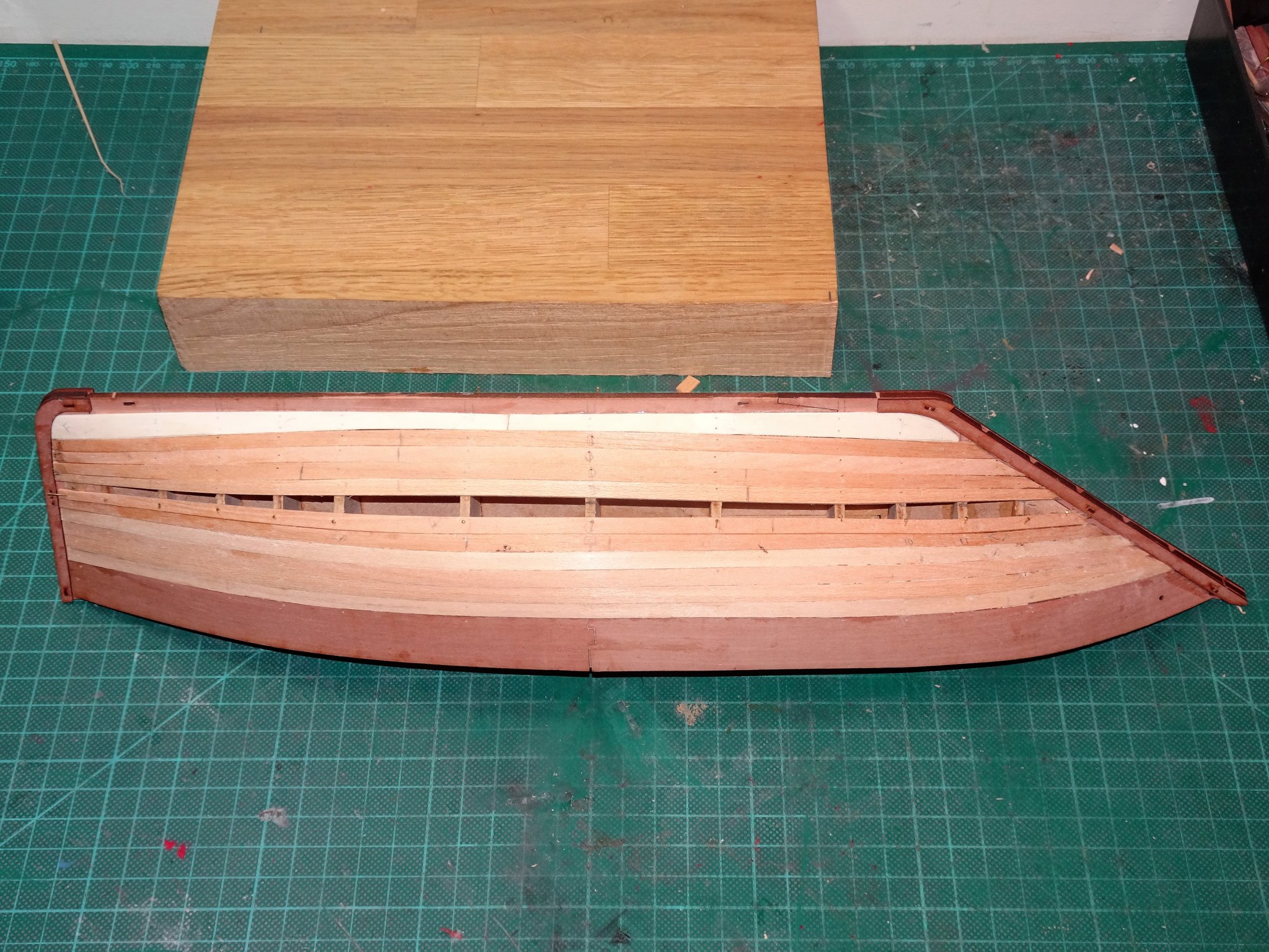
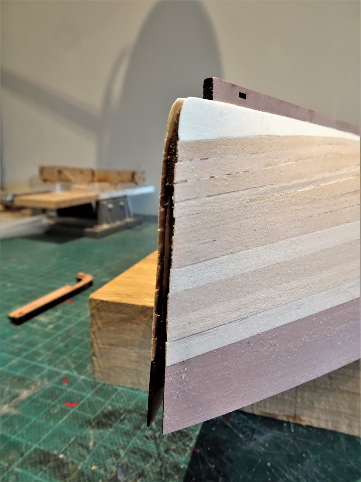
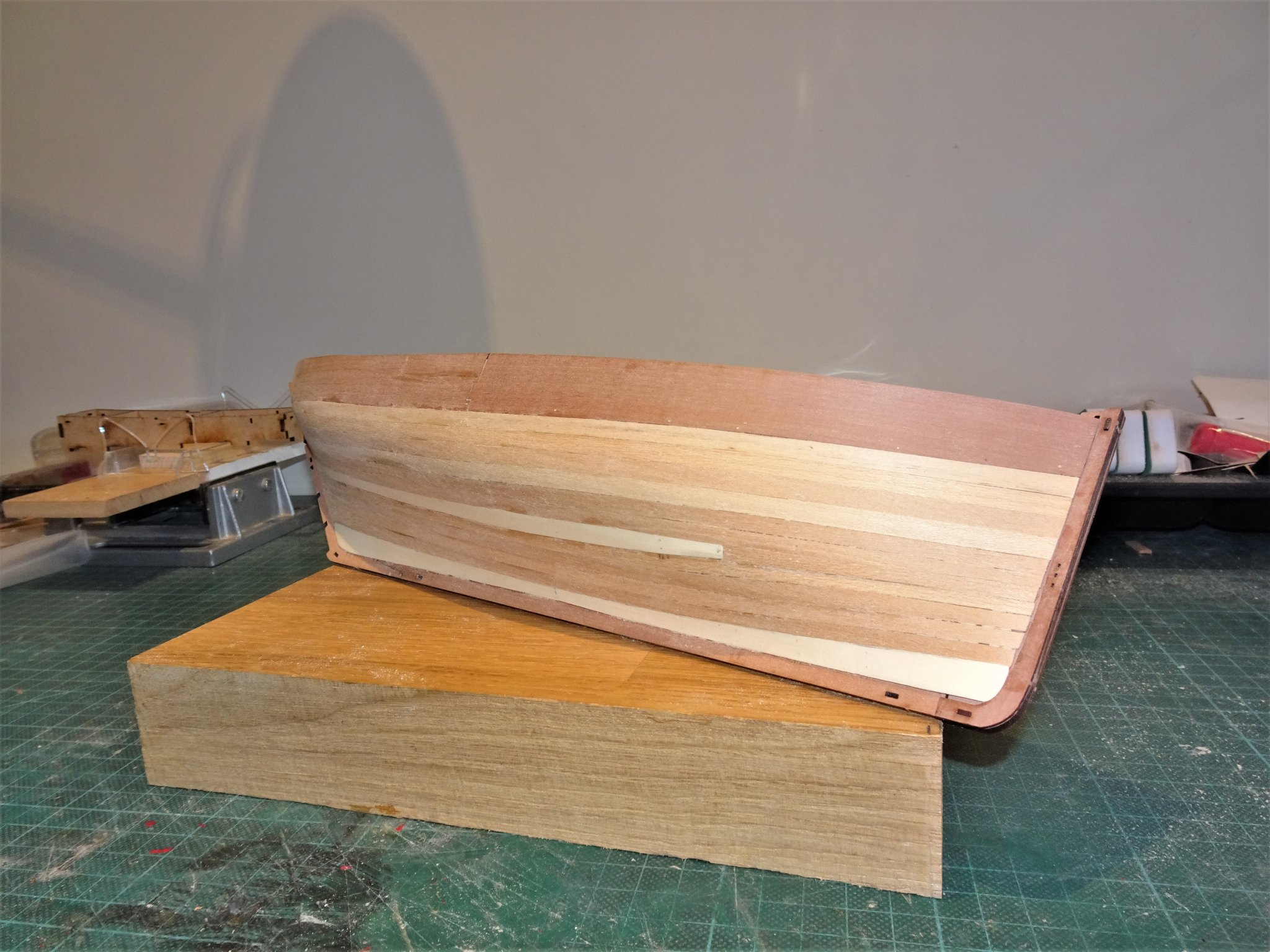
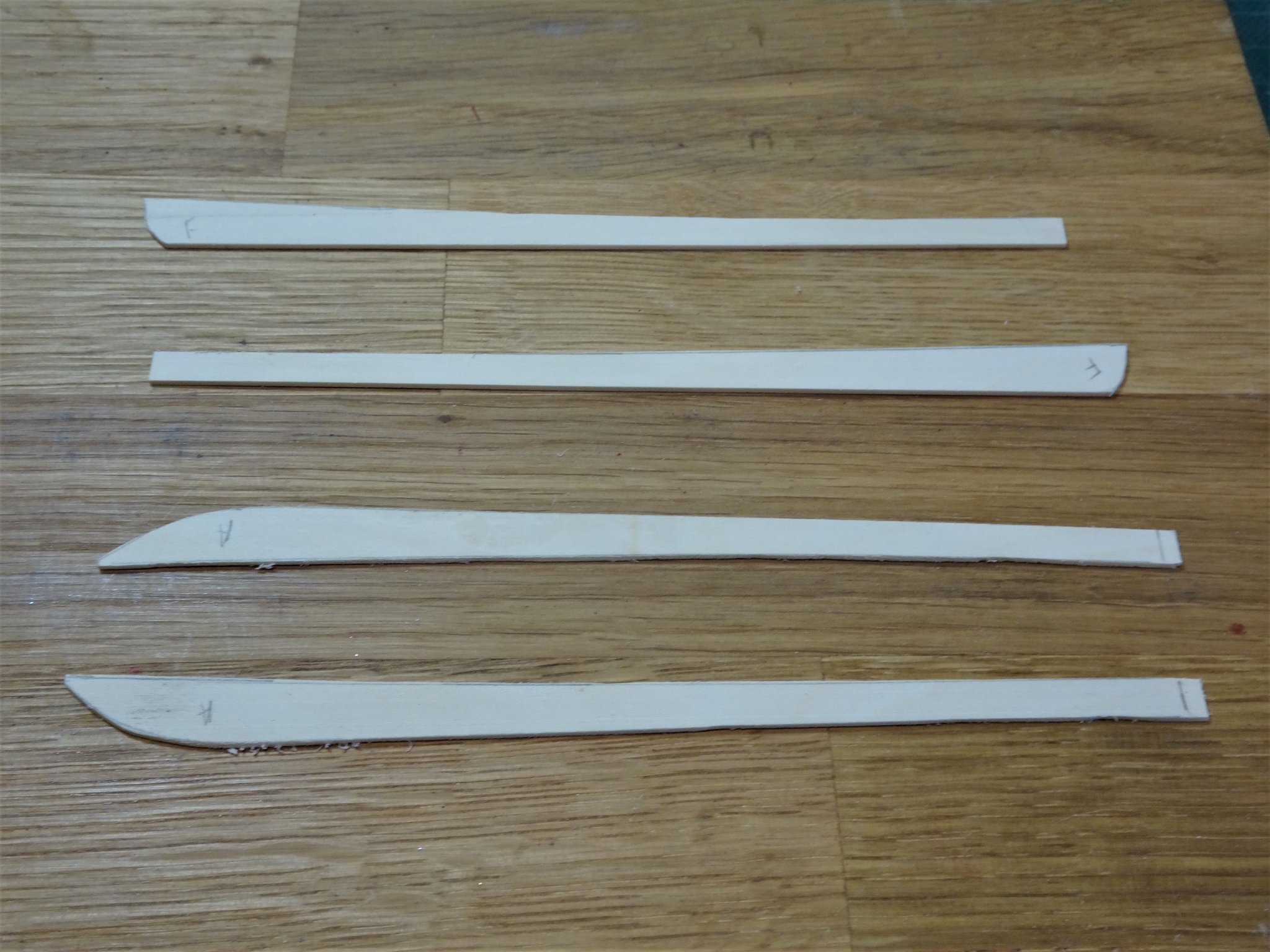
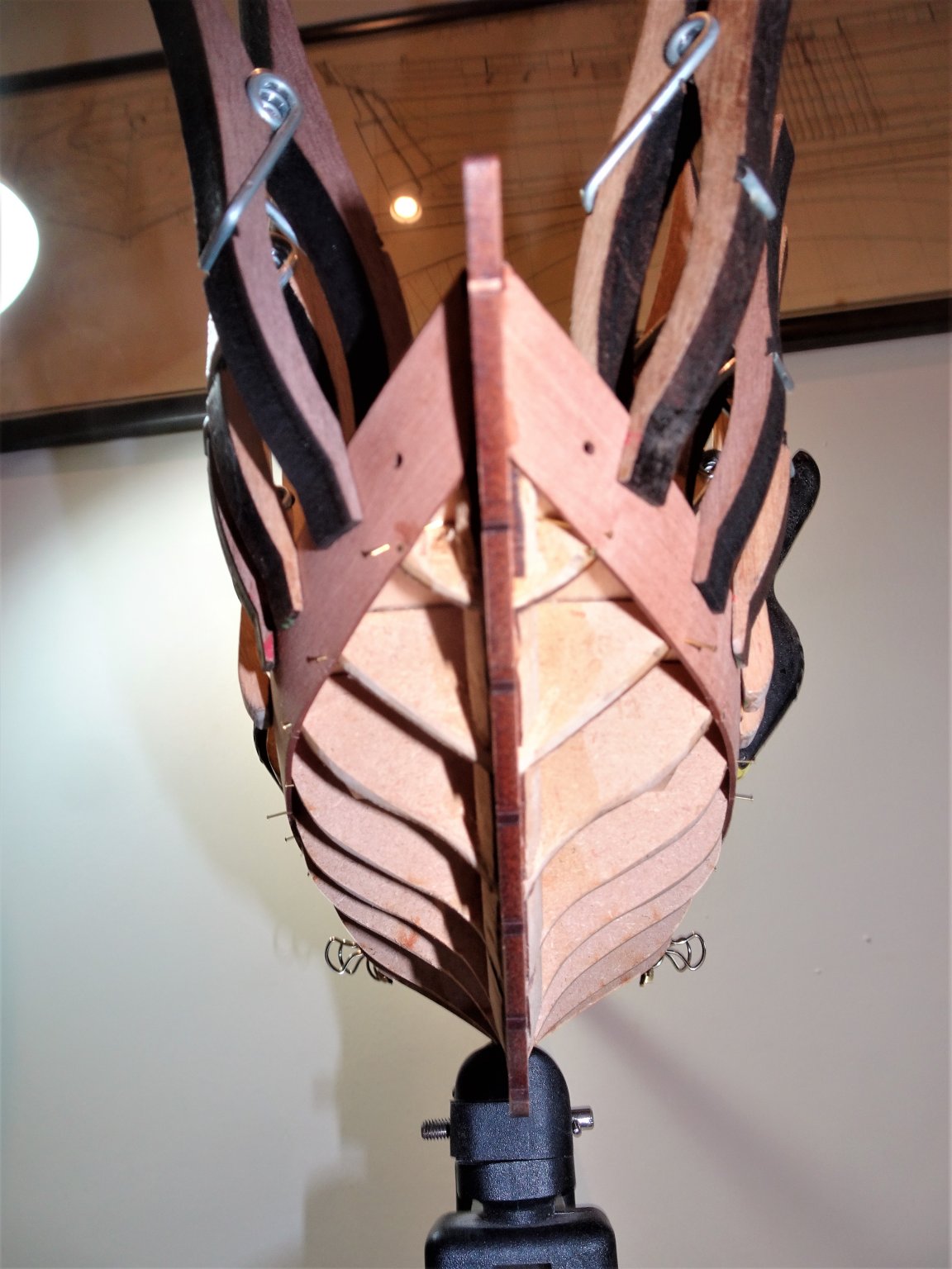
Post 4 Completing the first layer. I start with the plank immediately above the Garboard, but here I have the hull inverted. 6802(2) Using a tick strip I have marked next to the stem and stern the widths of the planks at that point. These are used to gauge the taper necessary towards the bow; at the stern no taper is required, but a twist is imparted so the plank lies flat against the false keel. The taper at the bow is still cut on the upper edge, but as the hull is inverted it appears to be the lower edge. 6807(2) I then added three further strakes from the keel up. 6813(2) The remaining two strake space is now looking more even from stem to stern but I re-mark the four tapers on bulkheads 10 and 11. 6829 The remaining strake will require spiling and the outline is marked using Tamiya tape. 6827 I always try to arrange for the spiled plank to appear beneath the round of the hull. 6889(2) The final two planks were cut from Holly sheet, in retrospect I should have ordered a few strips of 10mm wide Limewood strip, I don’t really like using a quality wood for under planking. 6878 I am spending a fair bit of time sanding the hull, paying particular attention to the bow and stern where a feather edge is required to allow for the second planking to fit well against the ‘false rabbet’. 6884 I don’t wish to get into too much sanding of the Pearwood planking to get the ends to lie flush against the stem post. 6899(2) 6877 I’ll fiddle around with the sanding awhile yet until I’m happy with the fit of the second planks against the stem and stern posts. B.E. 28/08/20
.thumb.JPG.39b62d3e5154ffb2a03d89827157fe45.JPG)
.thumb.JPG.b346e8fa489d76682bf160d8f3e8f989.JPG)
.thumb.JPG.e2b6944c3126babef1085a8e39d9f23b.JPG)


.thumb.JPG.5dbb6de1f8b7e5c6f01c8c18f3c7c199.JPG)
.thumb.JPG.c9761b5e3a7f172f4e6d150130b1268a.JPG)
- 261 replies
-
- 16
-
-
- muirneag
- vanguard models
- (and 2 more)
-
Hi Tim, personally I’m not a fan of the black seizing around the bulwark ring, I think it would look better using natural thread. My own preference is to use a false splice; thread the end thro’ a needle, pass it thro’ the line close to the ring a couple of times, smear pva over it and roll thro your finger and thumb, and trim. Cheers, B. E.
- 436 replies
-
- 2
-
-
- vanguard models
- alert
- (and 1 more)
-
Nice work on the hull, well done. 👍 The Pearwood comes up very nicely simply using wipe-on -poly. It is easy to make your own with oil based polyurethane thinned 50/50 with white spirit. It is also much cheaper than ready mixed stuff such as Minwax. I've no experience of using water based poly to make wipe- on but I 've read that it can be a little more tricky, and perhaps with less consistent results. B.E.
-
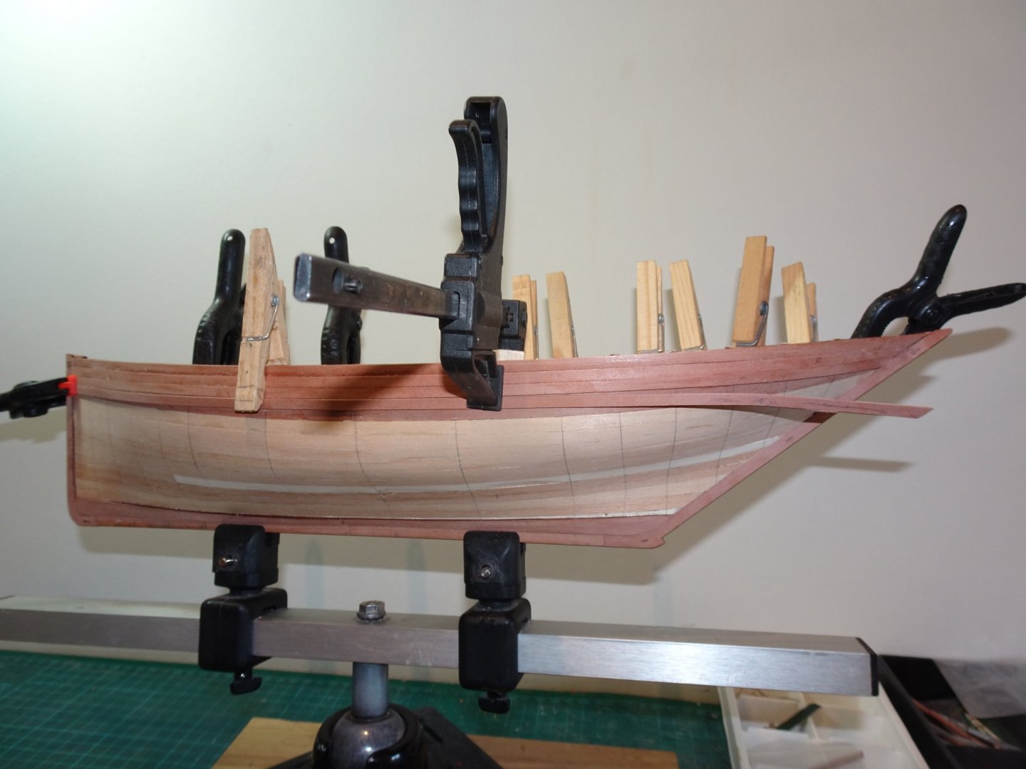
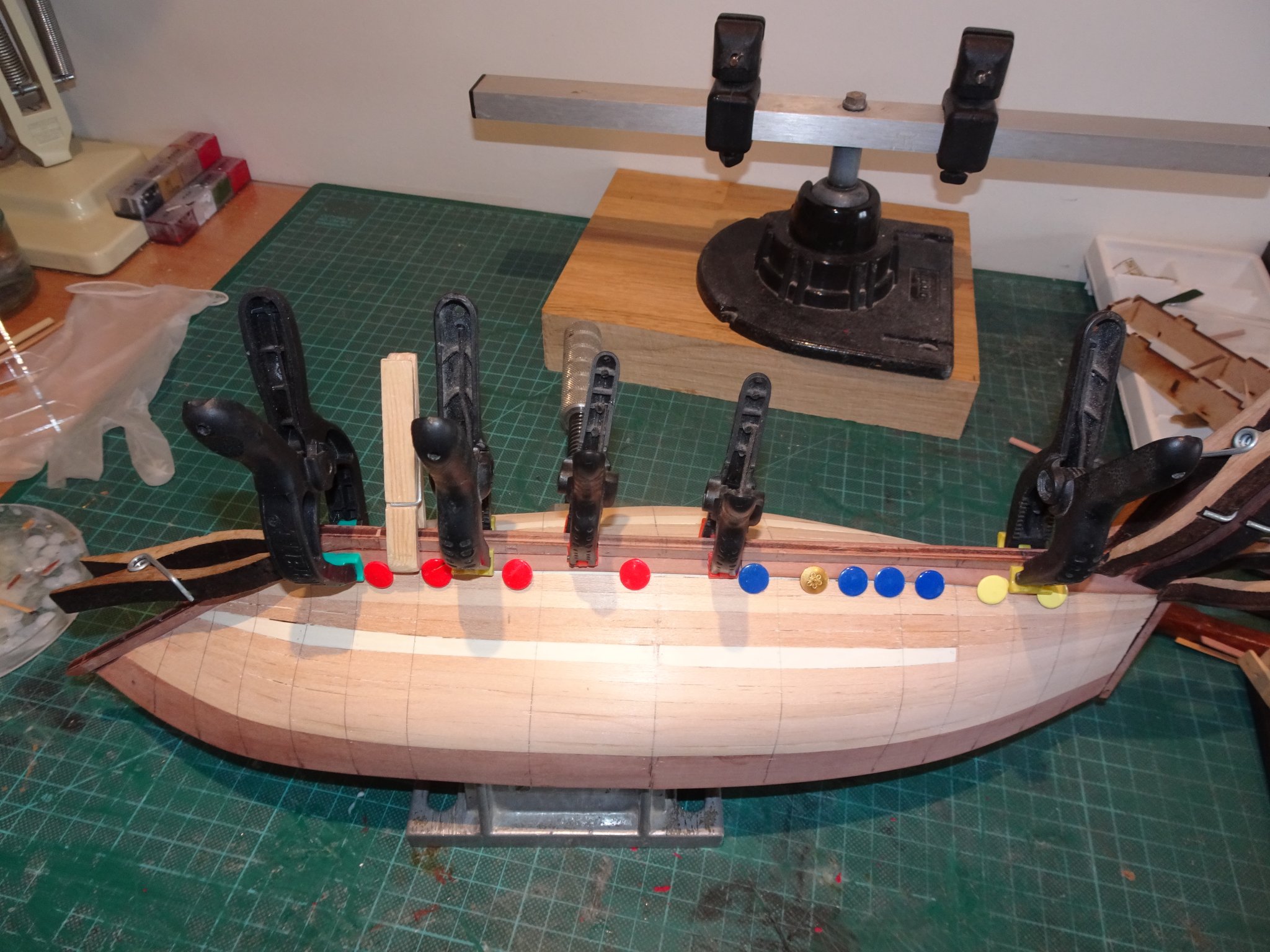
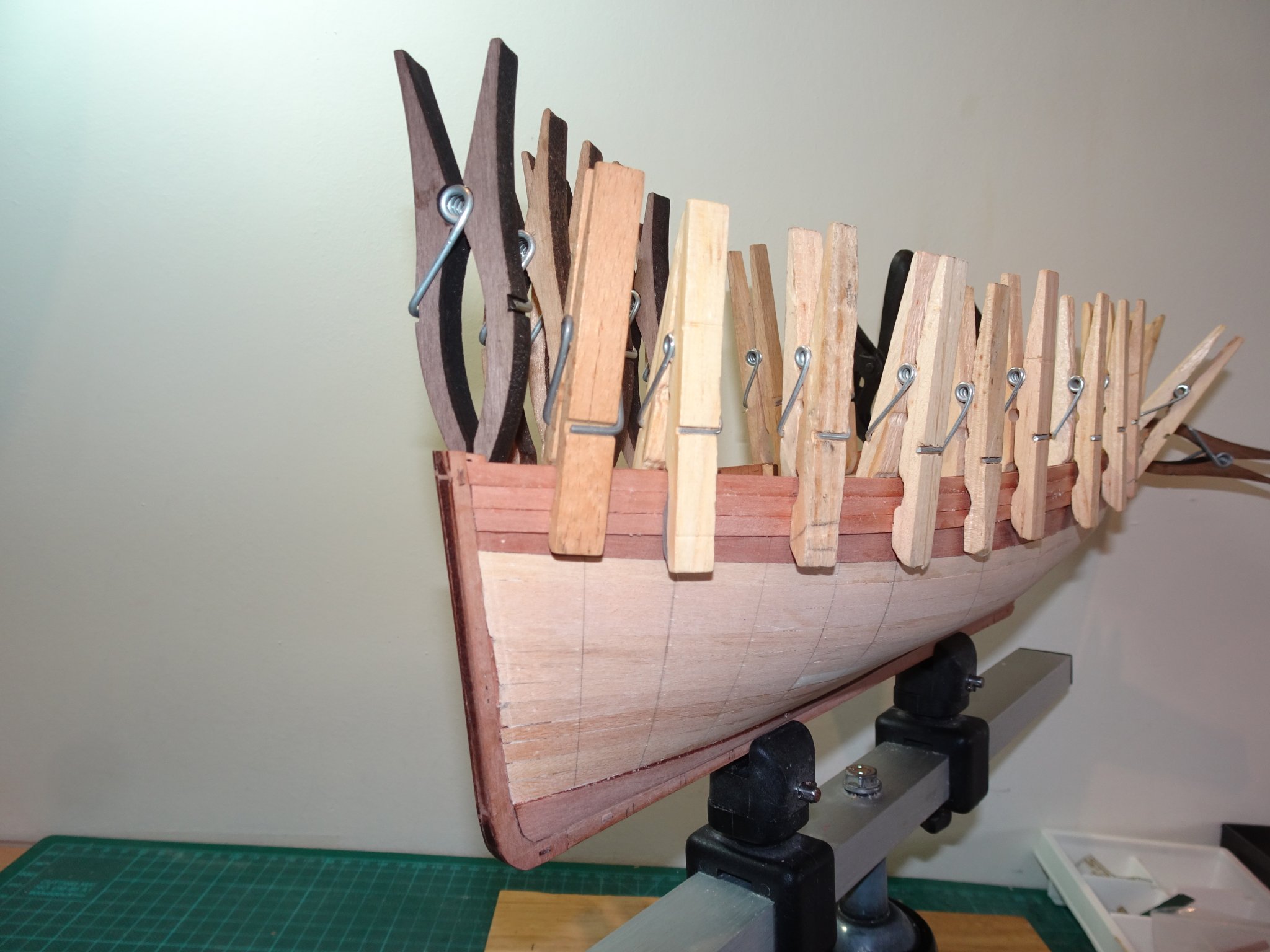
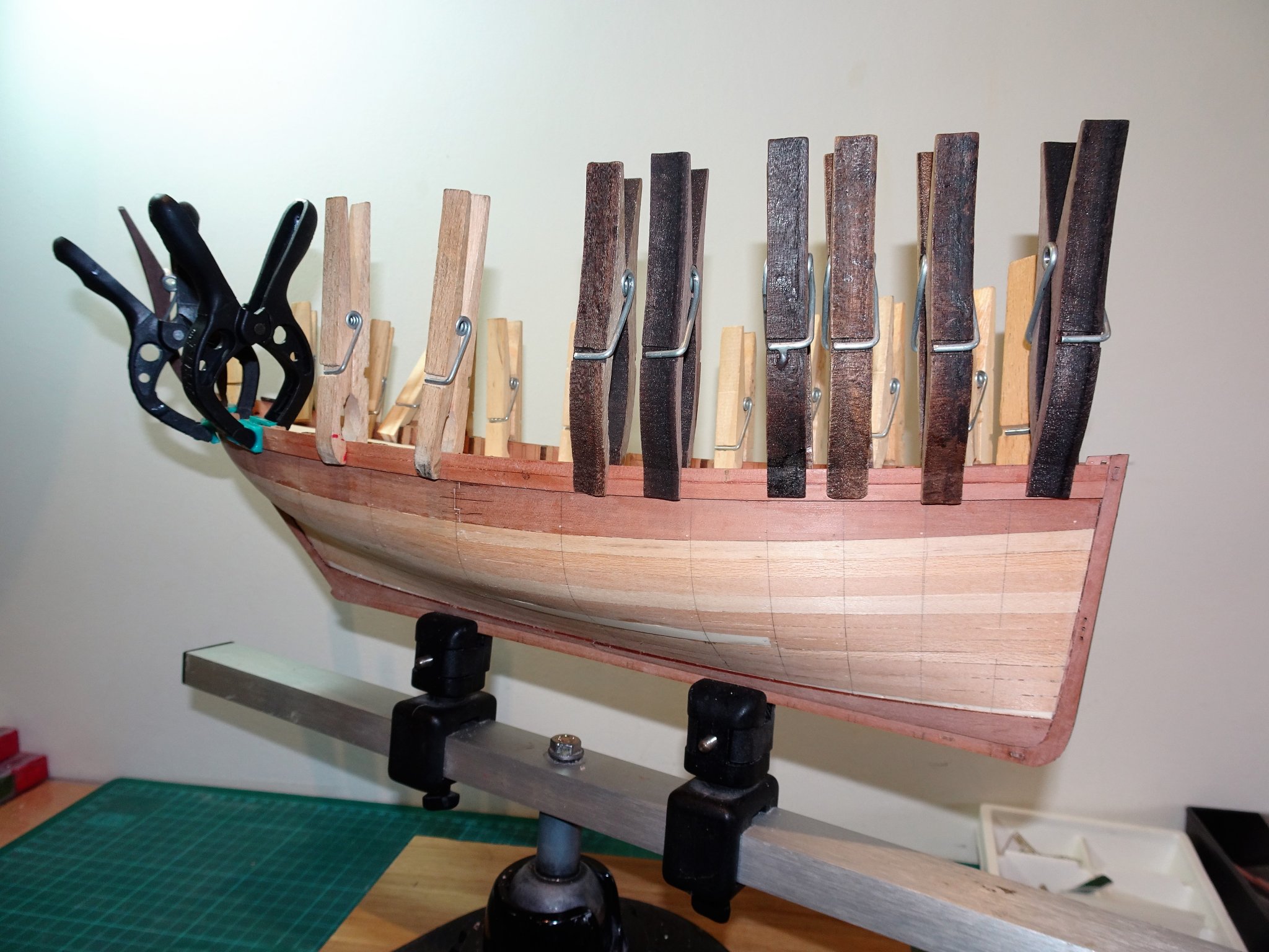
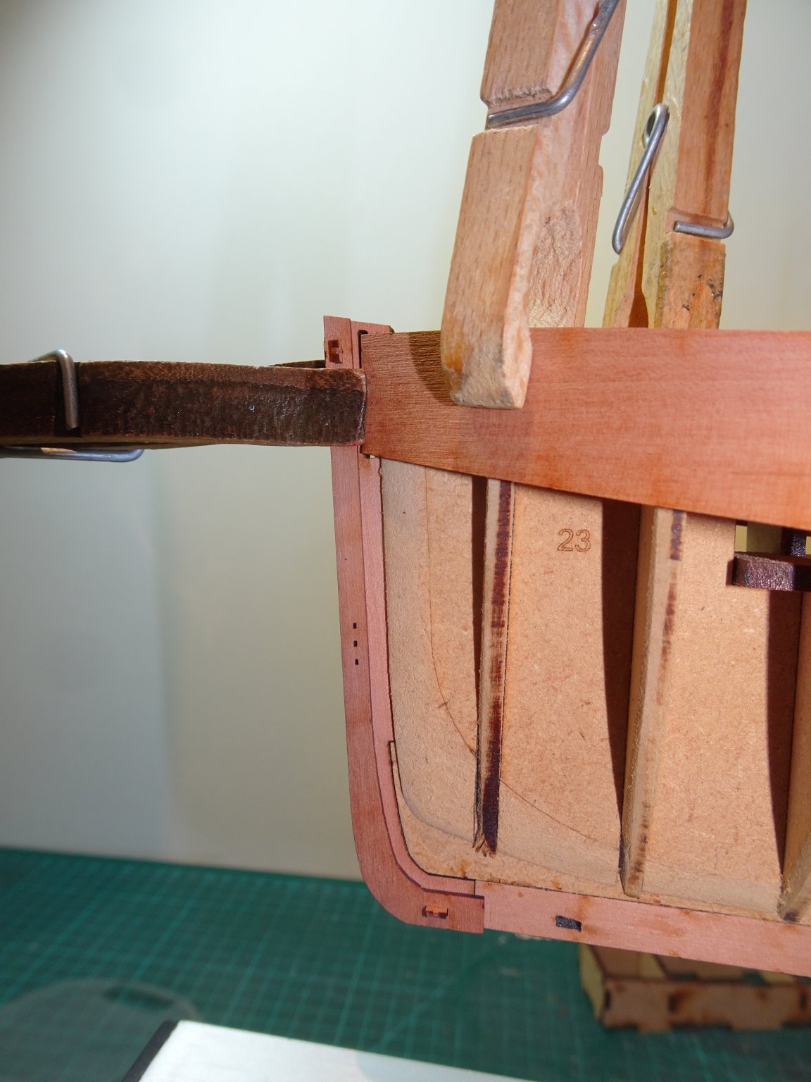
Post 3 First hull planking. Recalling my experience with the Fifie build it strikes me that the fore and aft filling pieces need a fair bit of further fining down otherwise there will be problems of getting the final planking to look like it fits flush in a rabbet at the stern and stem posts. The final pearwood planking is 1mm thick, as is the secondary stern and stem pieces which form the ‘rabbet’. 6716 It follows that the first limewood planking (1mm) which butts against the stern post and ultimately lies against the stem post will require sanding down to 0.5mm or preferably less to allow the top planking to lie flush against the secondary pieces with the minimum of sanding. Once the second planking is completed the stem piece will need to be used to check that the first planking is adequately feathered to allow this. The guide suggests that the planking starts at the stern and runs to the bow, where without the stem in place only a rough cut is required. I prefer to work from bow to stern so I intend to set the plank ends at the bow using the stem piece as a guide. For the first planking I decided not to fully line out but work by eye and hand to judge required taper and edge bend. I fiddled awhile with the first strip below the pattern and decided that there was no need to taper from midships forward, but a small taper was required at the aft end from around the third bulkhead from aft. 6744(2) With the plank clamped in place from stem to stern I marked the sharply angled stern end against the sternpost. This was cut and again tested along the hull where a final adjustment was made including any requirement for edge bend. A final check and the plank is glued and pinned. 6775(2) Four planks down from the pattern and taper and edge bend is only required from four or so bulkheads from aft. At this point I look at the Garboard plank. Chris has been kind enough to provide pre-cut Garboard planks for the second layer Pearwood planking. 6748 I used these as a template to make equivalents for the first layer which I cut from some 1mm Holly sheet. 6756 Fitting the Garboard strake. 6764(2) 6765(2) The Stem post is only dry fitted at this stage. 6777(2) 6781 Four strakes and Garboard fitted. From the fifth strake down there is tapering and edge bending required for both ends 6761(2) This photo shows the extent of taper and edge bend required My approach is to taper and edge bend from midships forward, then temporarily hold in place while the taper and edge bend from midships aft is determined. 6787(2) 6791(2) 6790(2) There are now six strakes left at midships, so I will do a tick strip exercise at the forward and rear bulkheads to gauge the taper requirements before completing the first planking layer. B.E. 25/08/20
.thumb.JPG.2b357c921ab3d6be451618e3a7dba481.JPG)
.thumb.JPG.b58f0bd8d54b467e3530f8798f07ab24.JPG)
.thumb.JPG.18b86f3e518e25d2dd44786540e39d1e.JPG)
.thumb.JPG.90622653dc715735ab4ebd2164881d5a.JPG)
.thumb.JPG.ecd0623a22a0545cbee242053be0f0e8.JPG)
.thumb.JPG.c6ab272dc8b9f383f104211a54f2aae9.JPG)
.thumb.JPG.8850b4533458656ef7d95c3c329f1eb1.JPG)
.thumb.JPG.8fa831a597a78835afa5ad02931ab1eb.JPG)
.thumb.JPG.59900642b1a9518c32c933a02c1dc047.JPG)
- 261 replies
-
- 16
-
-
- muirneag
- vanguard models
- (and 2 more)
-
Enjoyed reading thro' your log Rusty, what a fabulous build, I hope you have somewhere special planned to show her off. As far as the deck is concerned, aesthetically I would go for Boxwood, but really it is how it suits your eye. ps. Nice to see you have a new canine assistant, every shipyard should have a dog (or two) 🙂 Regards, B.E.
- 642 replies
-
- 2
-
-
- winchelsea
- Syren Ship Model Company
- (and 1 more)
-
Once the sheer line is defined the Zulu emerges like magic 👍 B.E.
- 261 replies
-
- 2
-
-
- muirneag
- vanguard models
- (and 2 more)
-
Ah, that must be it, subliminal influence, - I drive a 'full fat SUV' 😄 B.E.
- 261 replies
-
- 4
-
-
- muirneag
- vanguard models
- (and 2 more)
-
I tend to agree with you Glenn which is why I chose the Fifie for the first build, and the Zulu is a more tricky hull to plank. Still I think she will look stylish once the hull is completed, first planks on this afternoon.🙂 Cheers, B.E.
- 261 replies
-
- 3
-
-
- muirneag
- vanguard models
- (and 2 more)
-
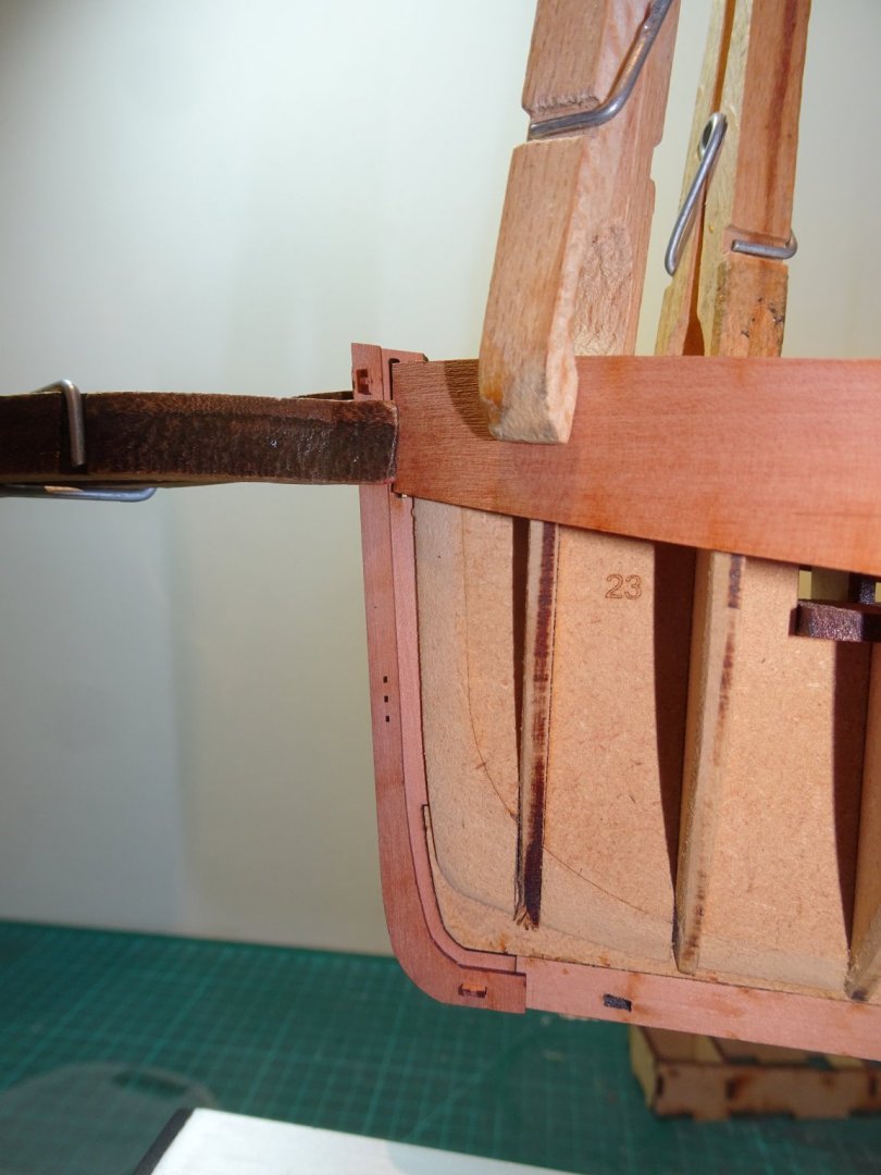
Post 2 Preparing for planking The first step is to complete the fairing and add the Bulwark patterns. Fitting the bulwark patterns is a fairly painless exercise. 6706 Starting with the aft patterns soaking and wet fitting to form the shape using clamps to secure above decks, and bulkhead clamps for the lower edge. 6721 I use a hairdryer to speed up the process to establish shape memory, and the patterns can then be attached. Only the area below the bulkhead tabs is glued, so again clamps only are used to hold the top line. The lower edge is pinned into the bulkheads. 6730 It helps to have everything to hand before starting, clamps, pins, pin pusher, and means to apply the glue. 6720 For positioning the pattern I use the lower of the two horizontal lines etched into the inside of the patterns, to align with the sub deck level. This is something that was mentioned in the Fifie build, but not in the Zulu manual. In practice the top of the pattern mostly aligns with the tabs. The Fore pattern bends easily around to the stem without the need for wetting. I did give it a blast of hot air whilst dry fitted and left it insitu overnight whilst the aft pattern was curing. 6726 The fore pattern on my build at least, was a perfect fit for length. I temporarily fitted the stem post and the secondary stem piece to assist with alignment. 6733(2) The distinctive sheer sweep to the stern now clearly apparent, plank tapering is going to be a significant feature of this build. 6731(2) In this photo the stem piece is only dry fitted. 6739(2) I now need to consider my approach to planking. B.E. 22/08/20


.thumb.JPG.805b85c73ffc8a3da75dc5e20b3a95f7.JPG)
.thumb.JPG.4e892f90a3d28a0e405c84c98aa1ad2b.JPG)
.thumb.JPG.0779164d734711ccbbea88933c660219.JPG)
- 261 replies
-
- 18
-
-
- muirneag
- vanguard models
- (and 2 more)
-
Hi Richard, I love my little miller, and it is certainly robust enough for model making. I have only used it for woodwork to date, slotting sheaves in catheads, milling profiles etc; There are reviews on the forum of the mf70 which may inform its use with metal, but it is designed for metal use. I hope to have a holiday around Anstruther and see the Reaper which I based my Fifie build on. Regards, B.E.
- 261 replies
-
- 3
-
-
- muirneag
- vanguard models
- (and 2 more)
-
That's a relief Chris, I can imagine the sinking feeling you must have had when the realisation dawned. If nothing else it will concentrate the minds of us early purchasers to check and double check. 😉 Cheers, B.E.
- 261 replies
-
- 2
-
-
- muirneag
- vanguard models
- (and 2 more)
-
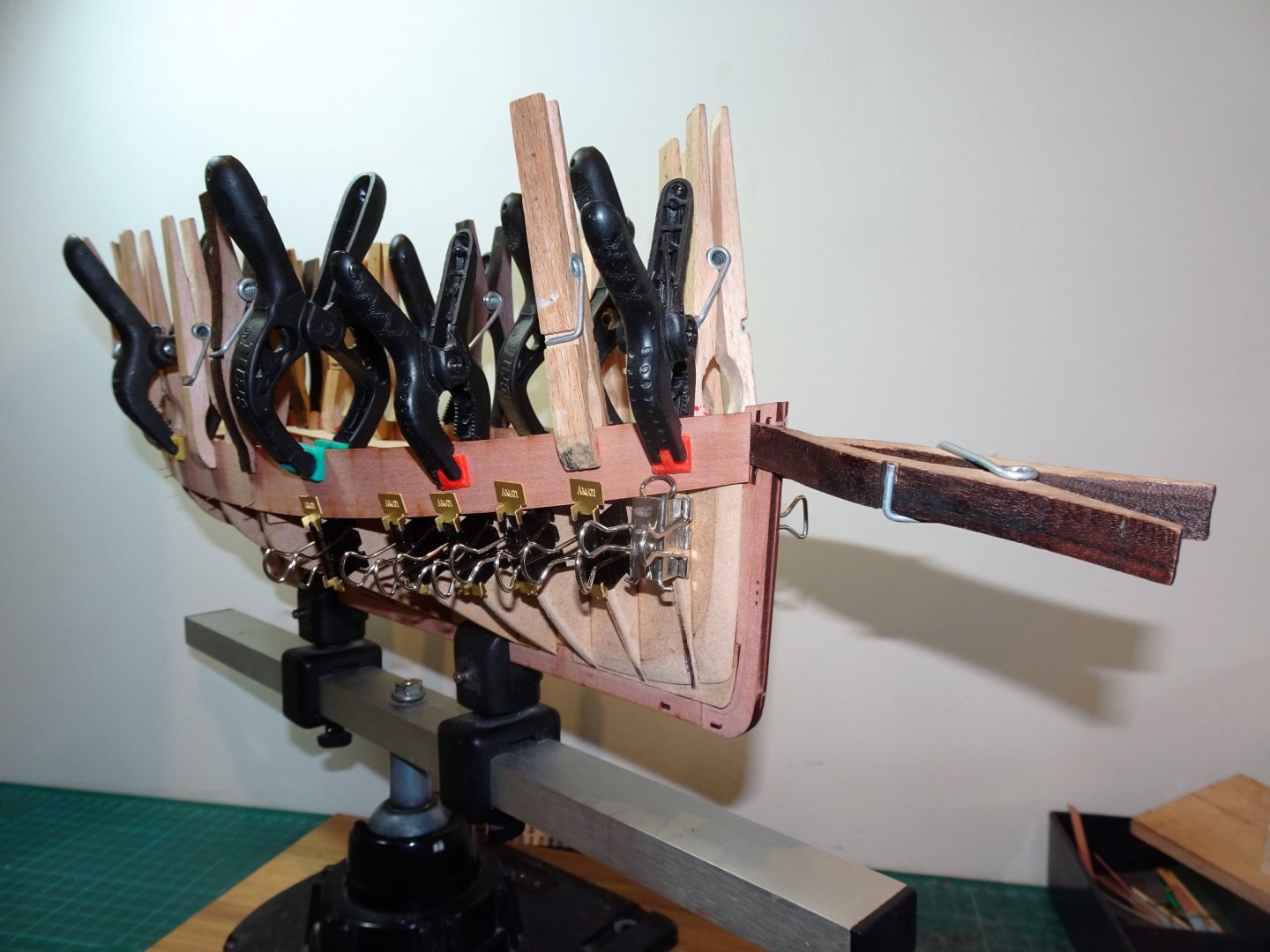
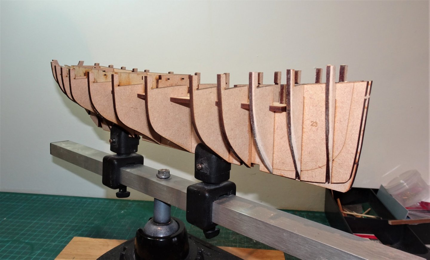
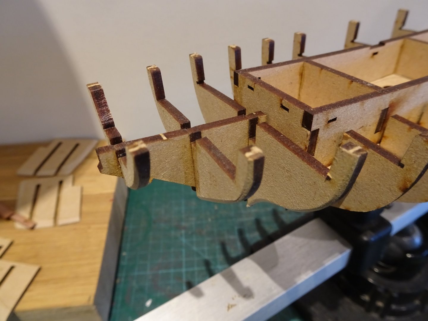
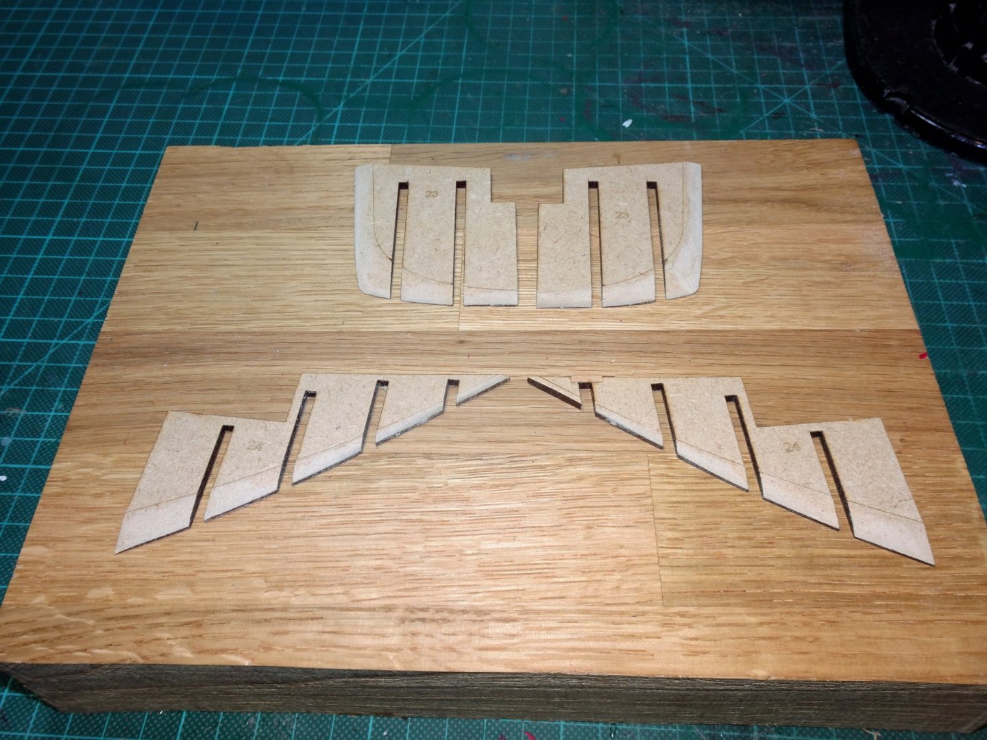
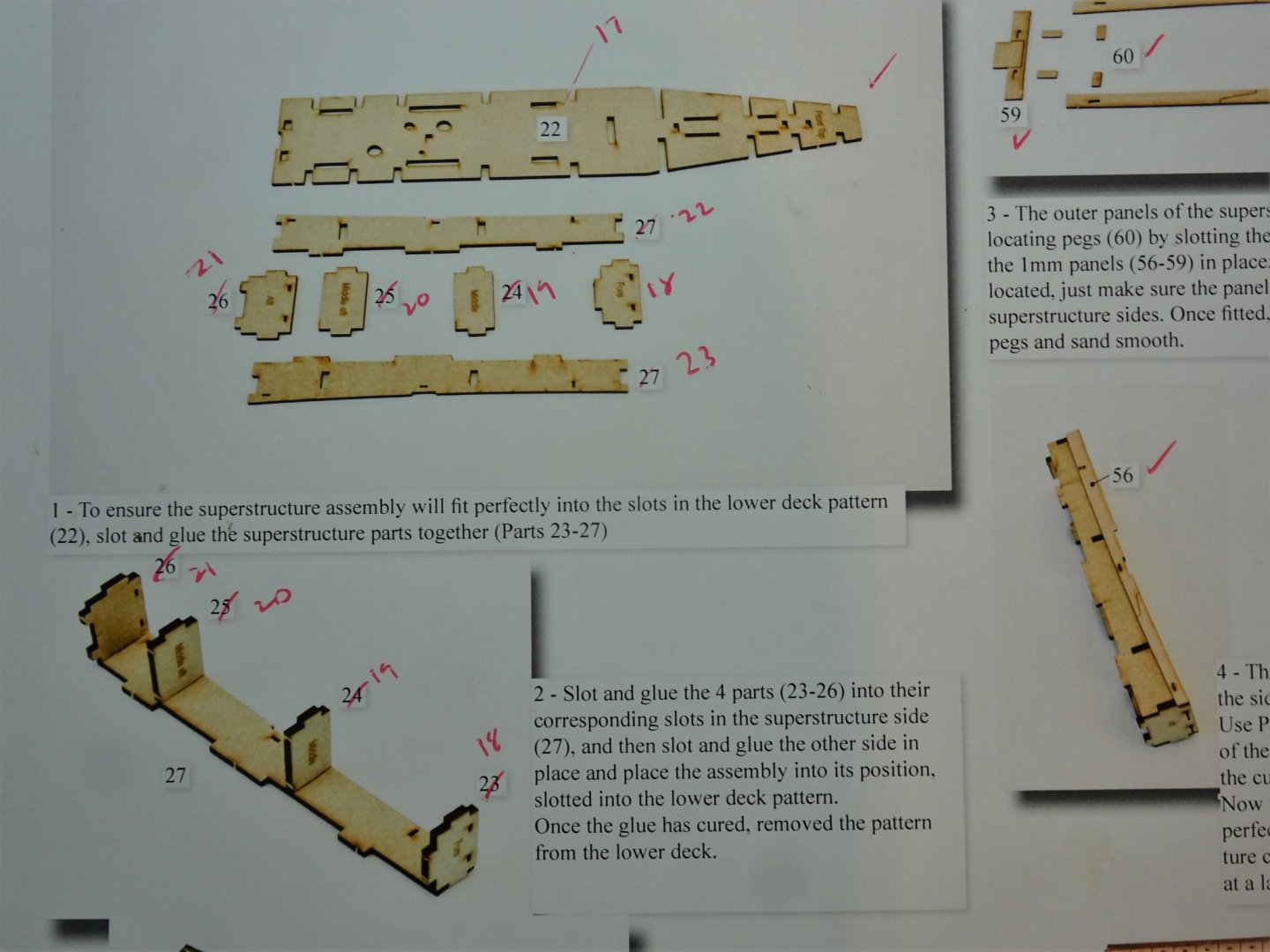
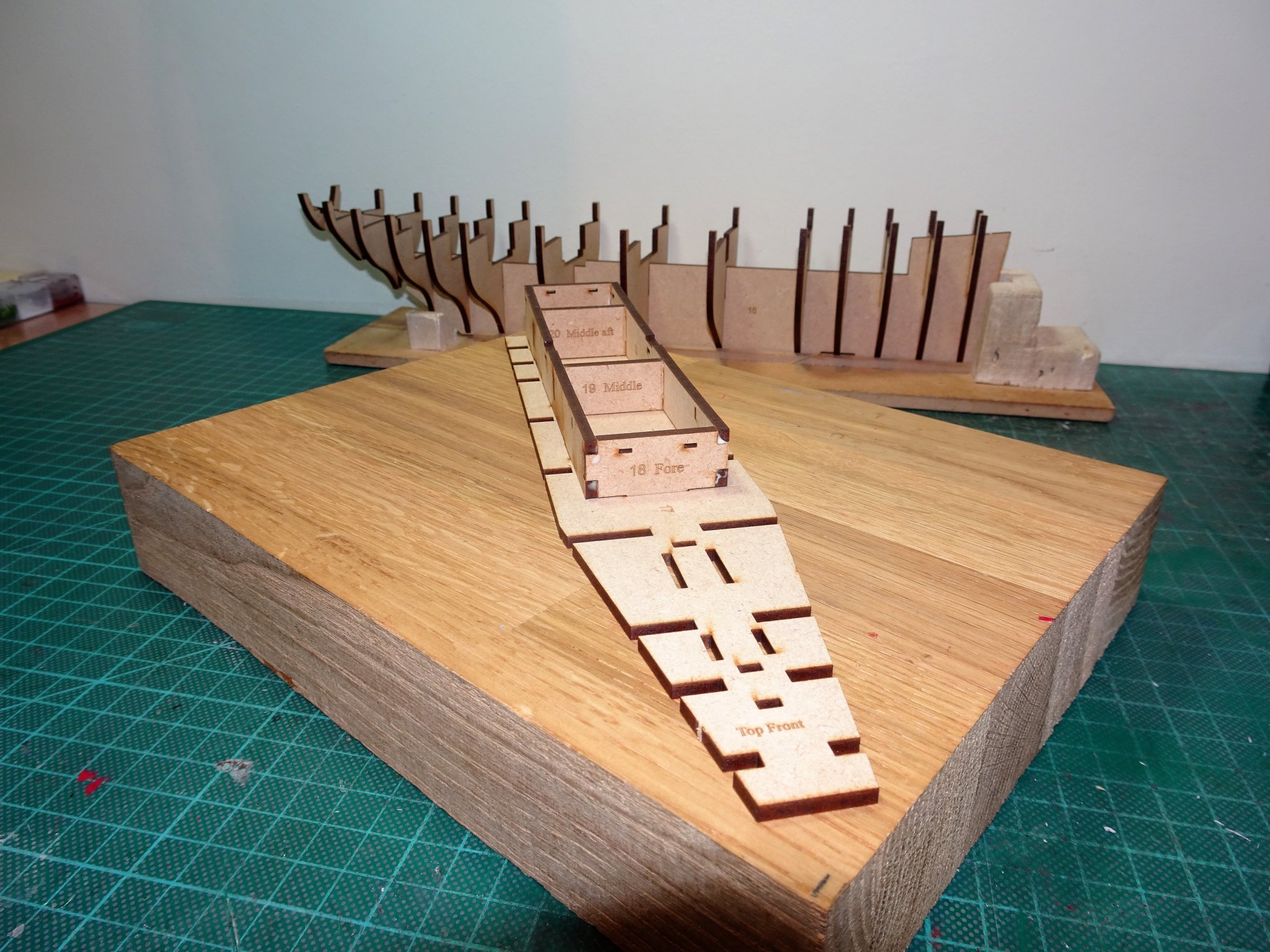
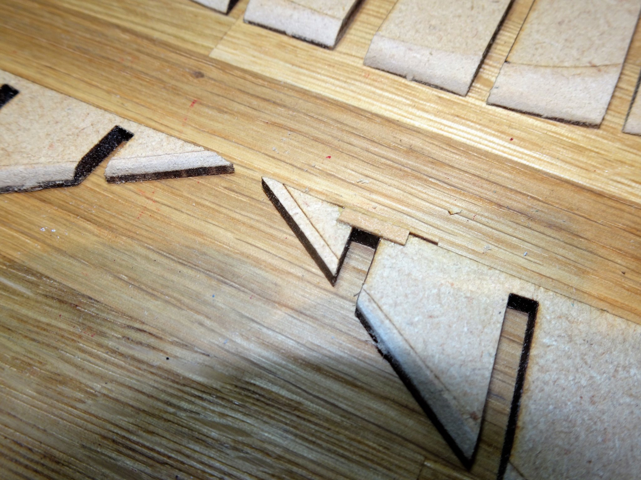
Post 1 First Steps - the basics. Usual stuff of assembling the false keel, bulkheads, and sub decks. Note: With the exception of the false keel (15) the other parts on the 3mm mdf sheet are numbered differently on the plan and in the manual. There are similar differences on the Bulkhead sheet, but the bulkheads do accord. 6671 A minor confusion and irritation and perhaps something that needs addressing going forward. I like to dry fit and fiddle around with the basic construction up to the fitting of the lower deck. The bulkheads are a slightly looser fit than on my Fifie kit, and to ensure proper alignment, once lightly glued on the false keel I used the lower floor, Lower deck pattern, and Fore and aft filling patterns to keep things ship shape. I initially glued the bulkheads 1-3 and then dry fitted the Fore filling pattern; followed by Bulkheads 10-14, secured by the Aft filling pattern; then the intervening bulkheads secured by the lower floor, and lower deck patterns. 6657 Any excess glue was removed from around the bulkheads before the dry fit items were put into place. The first three and last three bulkheads are marked for an element of pre-fit bevelling, which was done before fitting. As per the manual I also assembled the superstructure comprising a Poop deck, the companionway to the below cabin area, and Fish hatch, which is checked for fit in the lower deck. 6652 This structure won’t be needed for some time but is such that the fitting out of the Fish Hatch can be mostly done off model. The Poop decking will not be put into place at this stage as I intend to open up the Companionway. With the bulkheads fixed, the filling patterns are bevelled and glued into place, followed by the lower floor and deck pattern. 6665 The aft filling pattern is quite weak at its extreme end and one did snap during the bevelling process. 6667 Here temporarily supported until glued into place. Fitting the aft filling patterns gave me the most trouble at this stage. The Starboard pattern simply wouldn’t fit down flush with the keel without a deal of fettling, the port side was easier to fit but still needed a little slot sanding. I finally fitted them dry and ran diluted pva along the joints. At this stage the stern extension and last three bulkheads present a point of weakness. 6660 There is a risk that this section could snap off if knocked, or even by heavy handed fairing of the last three bulkheads, which is best left until the sub deck is fitted. The sub deck slotted between the bulkhead extensions without trouble and without any damage to the tabs. 6687(2) The structure is now strong and rigid and can be handled with more confidence. My final step in this stage is to add the rather nice Pearwood keel and stern post. 6695(2) These slotted together and into the false keel with an excellent fit. As with the Fifie kit Chris has provided a number of keel alignment patterns, a simple but innovative idea. 6689(2) Although shown in place here the manual calls for leaving the stem piece off until completion of the first planking; I’m undecided about taking this approach, my natural instinct is to rabbet the stem piece. Effectively the first planking needs to be reduced to a feather edge at the bow and stern to allow for the second planking to fit flush into the secondary stem piece which forms a rabbet for the Pearwood planking. B.E. 21/08/20


.thumb.JPG.38370344caf2f0d08600c03232676bd2.JPG)
.thumb.JPG.b64c49e957f812d1848b871dee4ddb9c.JPG)
.thumb.JPG.40855208591d62092e861f0bf9f4ad2d.JPG)
- 261 replies
-
- 15
-
-
- muirneag
- vanguard models
- (and 2 more)

.JPG.55feb379d9903256d28d769dcbf5170a.JPG)


.JPG.723b27af5af31c4f943b3c11b956bac6.JPG)
.JPG.b103655ba76b47c1b599f226a6217f46.JPG)
.JPG.cf0912b4b877fab10cdbfe1833015a9f.JPG)
.JPG.972d37d4fbd0cbc84e41bb5dc3fe78d7.JPG)
.JPG.dc3e17ac7a70e52e5cba660e6042682a.JPG)
.JPG.0f10ac12f6a0d921f43cf4e61fb640db.JPG)

.JPG.284e2e72b3da29b15e20feb0d9d3f8c7.JPG)
.JPG.3a87845fc543e7213929ee6dad5445c7.JPG)
.JPG.447adc6f6d71034eec67666f47991a95.JPG)
.JPG.d1b1075ccbecefdfd3632d2abd2fc66b.JPG)
.JPG.014ecad8c9daf3ec77dc5cdc6824aad9.JPG)
.JPG.c994d9d4924c2d65532c888f0afaad13.JPG)
.JPG.12e8aa84728f4638d33e0f0969b3940f.JPG)
.JPG.175c8069106e05b056226820a9a8ba15.JPG)

.JPG.f4aabbdcdee53911b8085e54ac1990c0.JPG)
.JPG.20ef2996d67fb482e9b2d7c9f7a30cae.JPG)
.JPG.5b553fc2ff6e8f5e6dab93f2bbfc586f.JPG)


.JPG.f2715a9cc3f55eb13363c54f6486629a.JPG)
.JPG.765cfceda0395c7e27e5b158c3b52cc5.JPG)
.JPG.54cdcacffe7ba9d318920c8d4e976fb3.JPG)


.JPG.140a77559087854a798e58490a1bc94a.JPG)
.JPG.da4717872358c7547eb8efa945ba1736.JPG)
.JPG.ec4ca419db6b1910bd2145ae1be29eaf.JPG)