
HOLIDAY DONATION DRIVE - SUPPORT MSW - DO YOUR PART TO KEEP THIS GREAT FORUM GOING! (Only 13 donations so far - C'mon guys!)
×
.JPG.ca33079f5815b861e67b9c2cccd37982.JPG)

Blue Ensign
-
Posts
4,564 -
Joined
-
Last visited
Content Type
Profiles
Forums
Gallery
Events
Everything posted by Blue Ensign
-
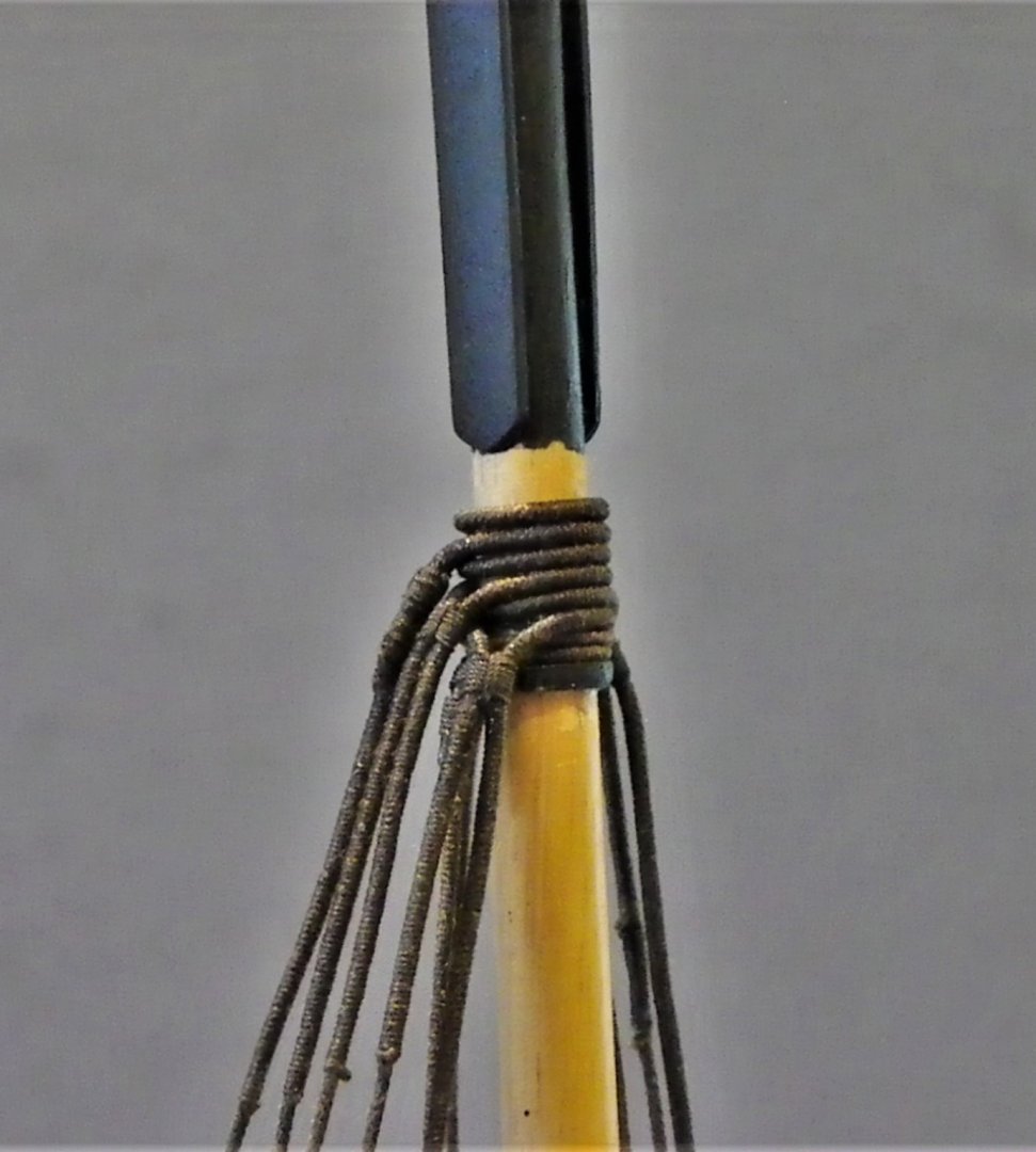
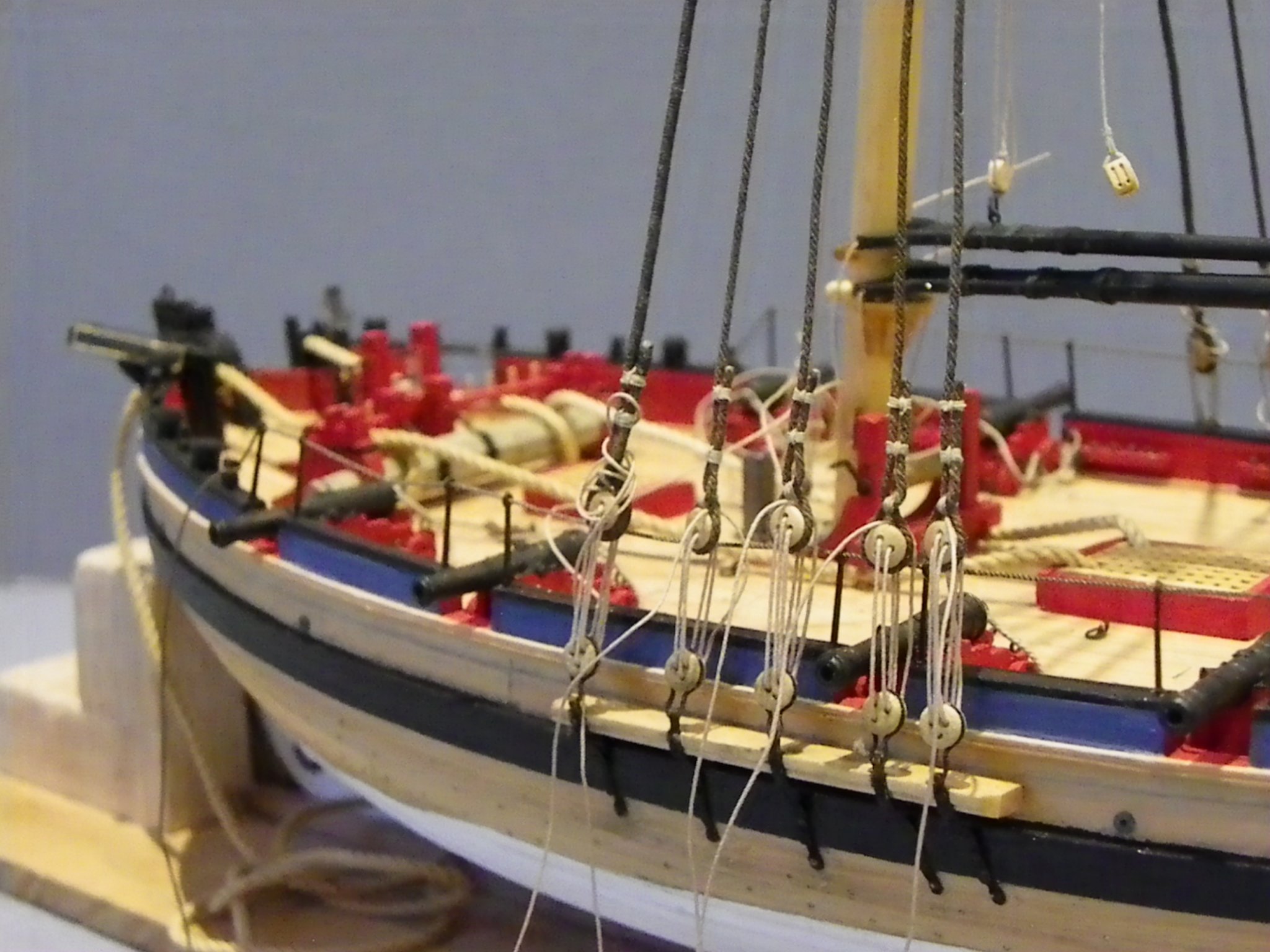
 Post 62 Time to attach the shrouds Not one of my favourite jobs stropping the upper deadeyes, but it’s that point in the build. It’s a little more tricky stropping the deadeyes if the correct procedure is followed whereby the line crosses in front of the shroud with a cross seizing above the deadeye before applying two further seizings to the standing part. 0195 Fitting the cross seizing. 0200 Seizing the shroud ends. 0202(2) The seized end lies aft on the Portside and forward on the Starboard side as shown above. I note that the centre channel deadeye has twisted around, one of the benefits of macro photo’s is highlighting issues. 0204 I rig the shrouds alternatively starboard and port, setting the level with the foremost shroud. From that point onwards I set them by eye as I move along the channel. I temporarily rigged a section of the rope guard rail as an additional guide. 0207 The seizings are yet to be dyed, I find it easier with my less than good eyesight to fit them in natural thread, better contrast against the dark shrouds. I am using Morope 0.1mm line for the seizing, and Syren 0.3mm line for the lanyards. I won’t tie off the lanyards until later in the rigging process, when I will adjust the final tension. 0203 0210 0212 0215 0216 A sort of build milestone when the shrouds are rigged, but there’s still a long way to go in this build. B.E. 29/01/2020
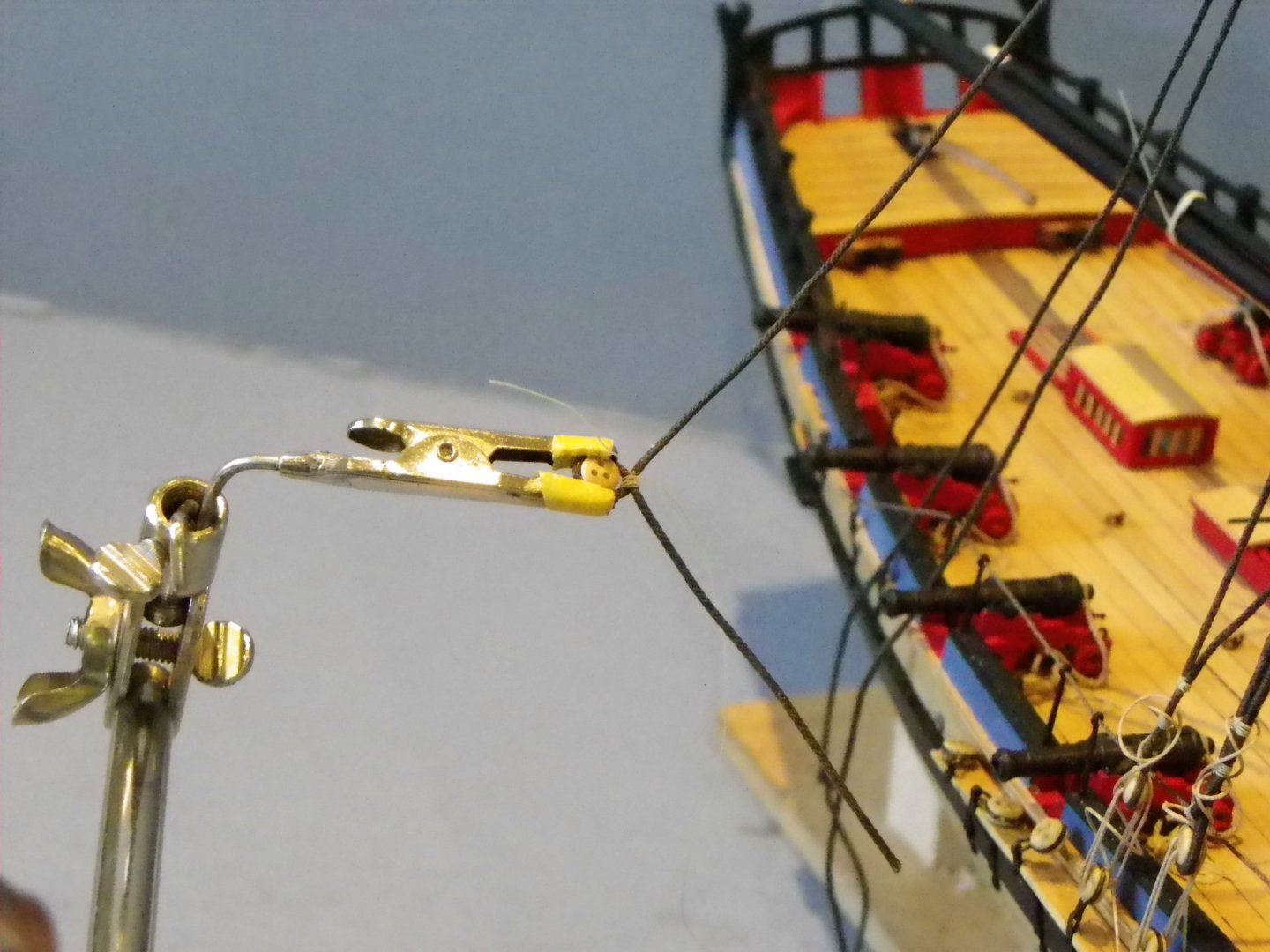
.thumb.JPG.9bc85566d7925e0df4ca0174b7b0680b.JPG)

- 335 replies
-
- 19
-

-
- alert
- vanguard models
- (and 1 more)
-
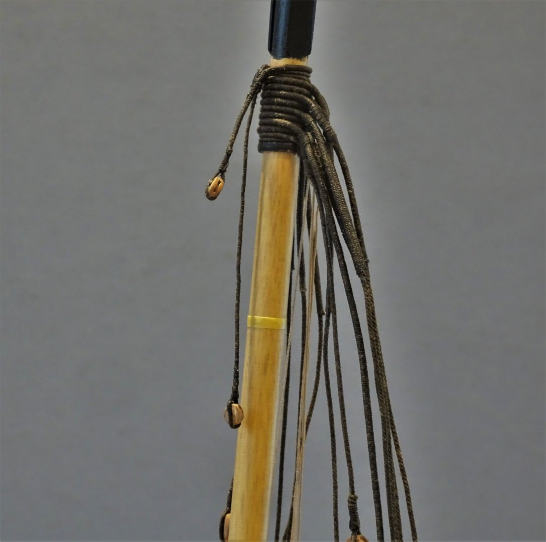
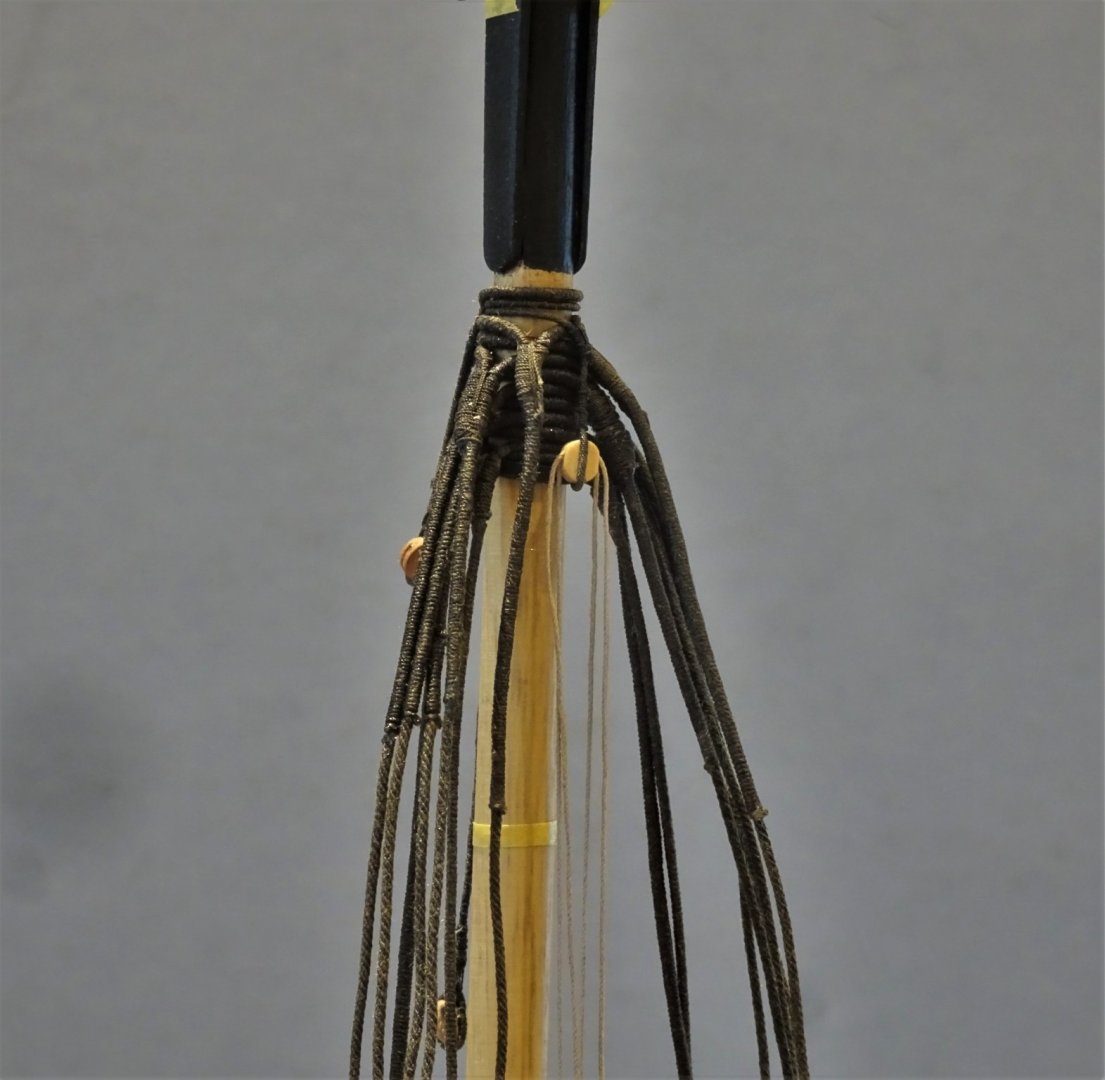
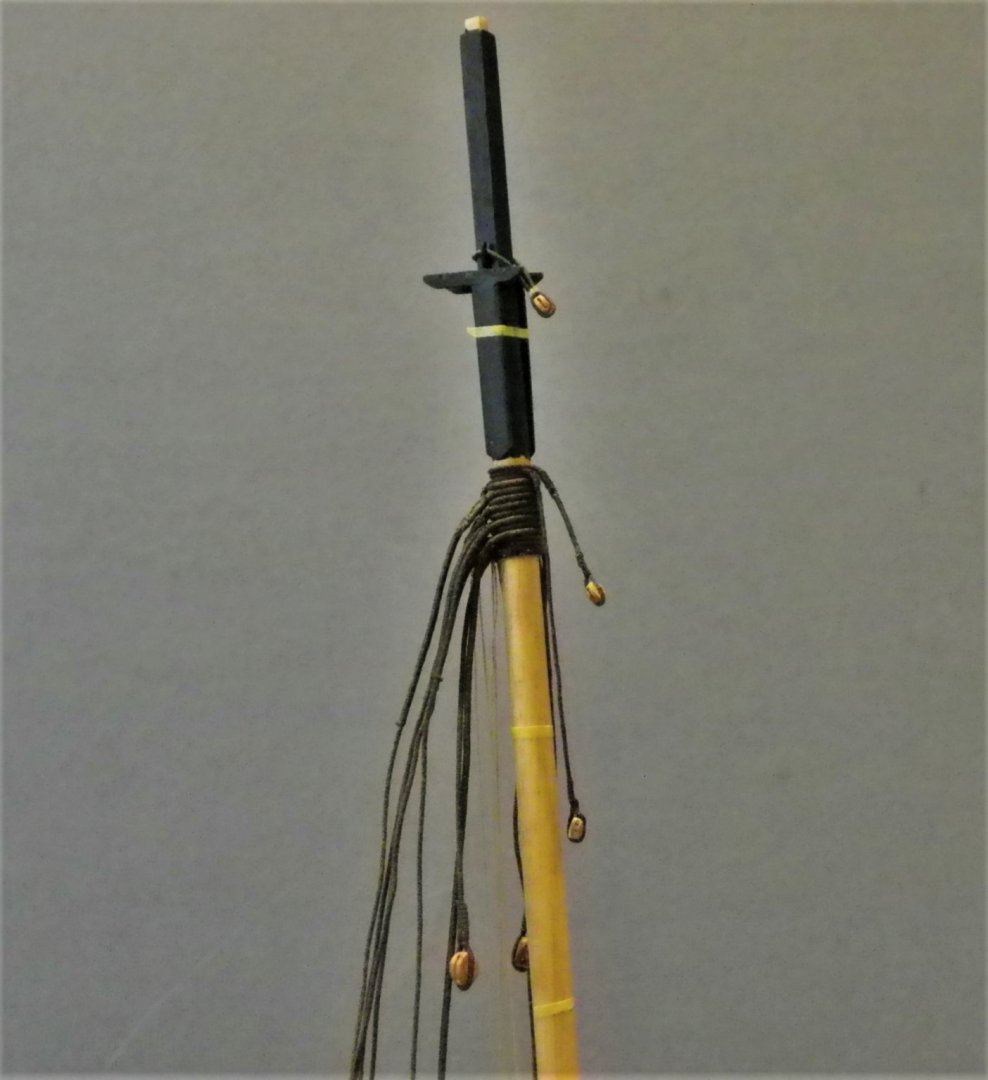
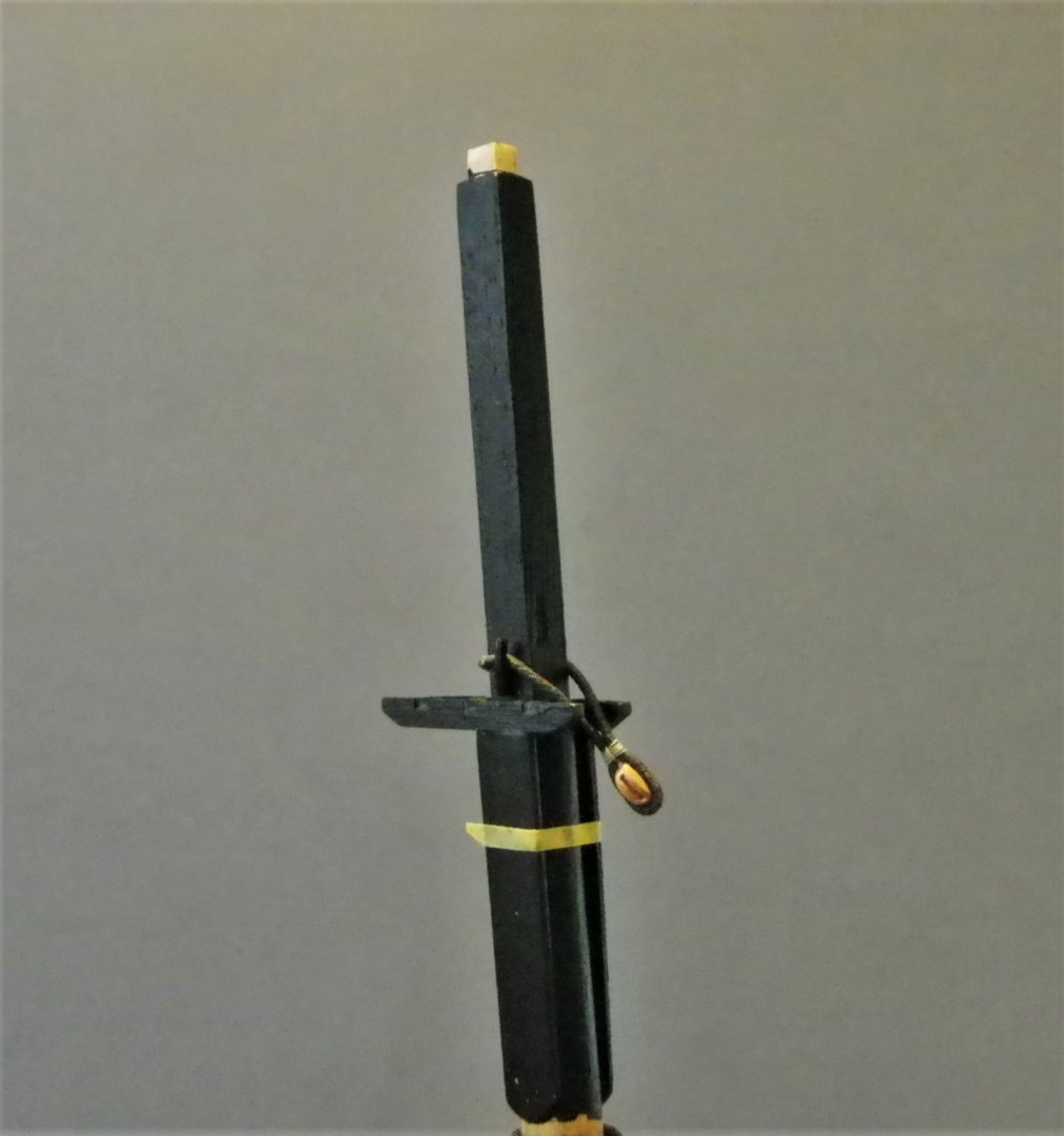
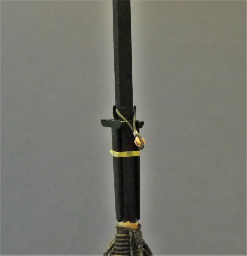
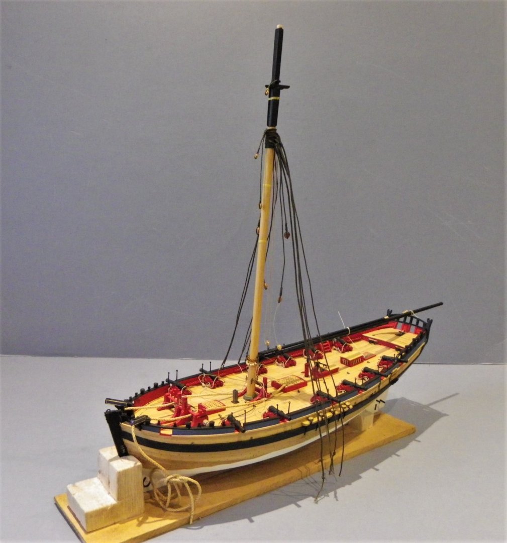
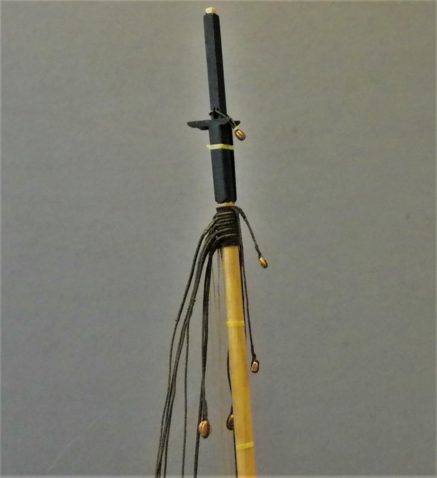
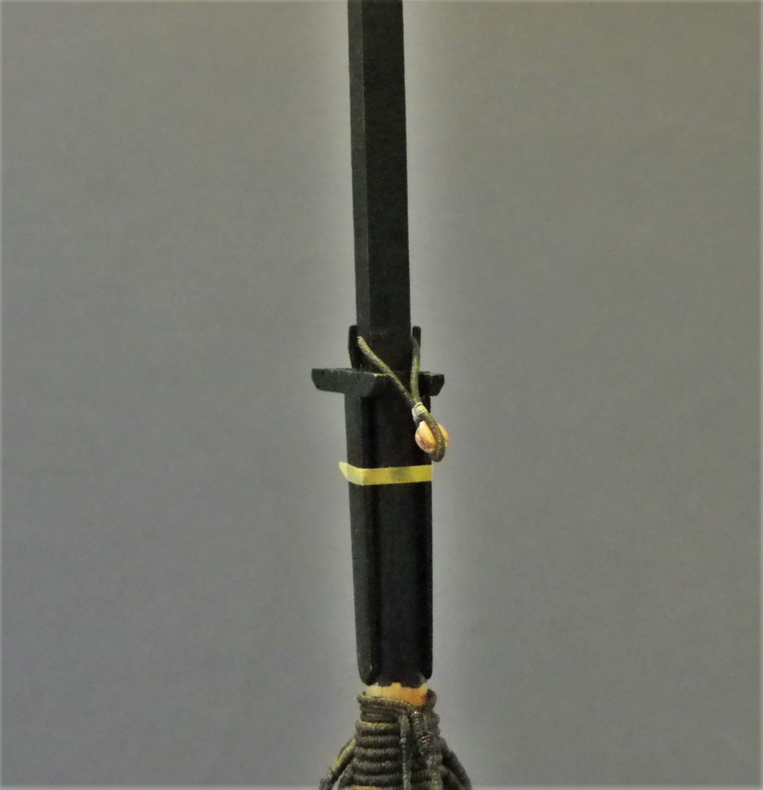
Post 61 Blocks and strops around the Masthead There are a number of blocks and strops to fit around the masthead for the yard ties, and other tackles. I held-off fitting these before stepping the mast and fitting the standing rigging so I could better assess the pendent lengths and positions relative to the yards. Atop the running backstays the pendent and strop for the Gaff jeer tackle block is fitted. 4418 A 4mm double block is stropped into the pendent. 4413 At the lower end a 4mm single block is hooked to the gaff. 4417 This now allows for the gaff and its tackle to be fitted to the model, temporarily secured at present in the lowered position. Above this are the pendents and standing blocks for the Spread-sail and Square-sail yards. I adopted the Alert book arrangement of hanging the Yard tye pendents from the mast head rather than follow the kit arrangement of having separate cleats to support the tyes at different levels down the mast. However, once again there are inconsistencies in the Alert Book Drawing H18/3 AND H22/1 show the spread-sail and Square-sail tye blocks in opposing positions. I took the view that the longer Spread-sail tye pendent went over the masthead first. 4408 Seizing the pendent around the mast head. 4416 The tyes were made from 0.3mm ø served line stropped with a single 4mm blocks. The final strop below the T’gallant mast is for the Topsail yard tye. 0180 0181 This fits between the trestletrees and is held in place by cleats on the Topmast head. 0179 The three standing tye blocks for the Topsail, Square-sail, and Spread-sail yards. 0187 0189 Now getting into a very messy stage with loose ends, there are still strops to make and the fitting of the horse to figure out. B.E. 27/01/2020


- 335 replies
-
- 22
-
-
- alert
- vanguard models
- (and 1 more)
-
Annoying but fixable, re-glue and splint either side using shaped narrow strips of limewood that can be faired along with the rest of the bulkhead. B.E.
- 436 replies
-
- 3
-
-
- vanguard models
- alert
- (and 1 more)
-
The Pearwood gratings are a big improvement Chris, and I would purchase them , had I not already replaced mine in Boxwood. I imagine the colour will come up very nicely with wipe-on poly. The Alert deck looks good on the photo with a realistic butt shift pattern, my only concern would be if a good clean finish can be obtained using limewood, it is a fairly soft wood. No doubt you will test it for taking a flat matt varnish before making a final decision. Regards, B.E.
-
Just checking Derek, is the vertical planking on the transom correct? I've not seen that configuration before, if you visualise the real thing, the stern frames are vertical, the planking is usually horizontal. B.E.
- 725 replies
-
- 2
-
-
- vanguard models
- speedy
- (and 1 more)
-
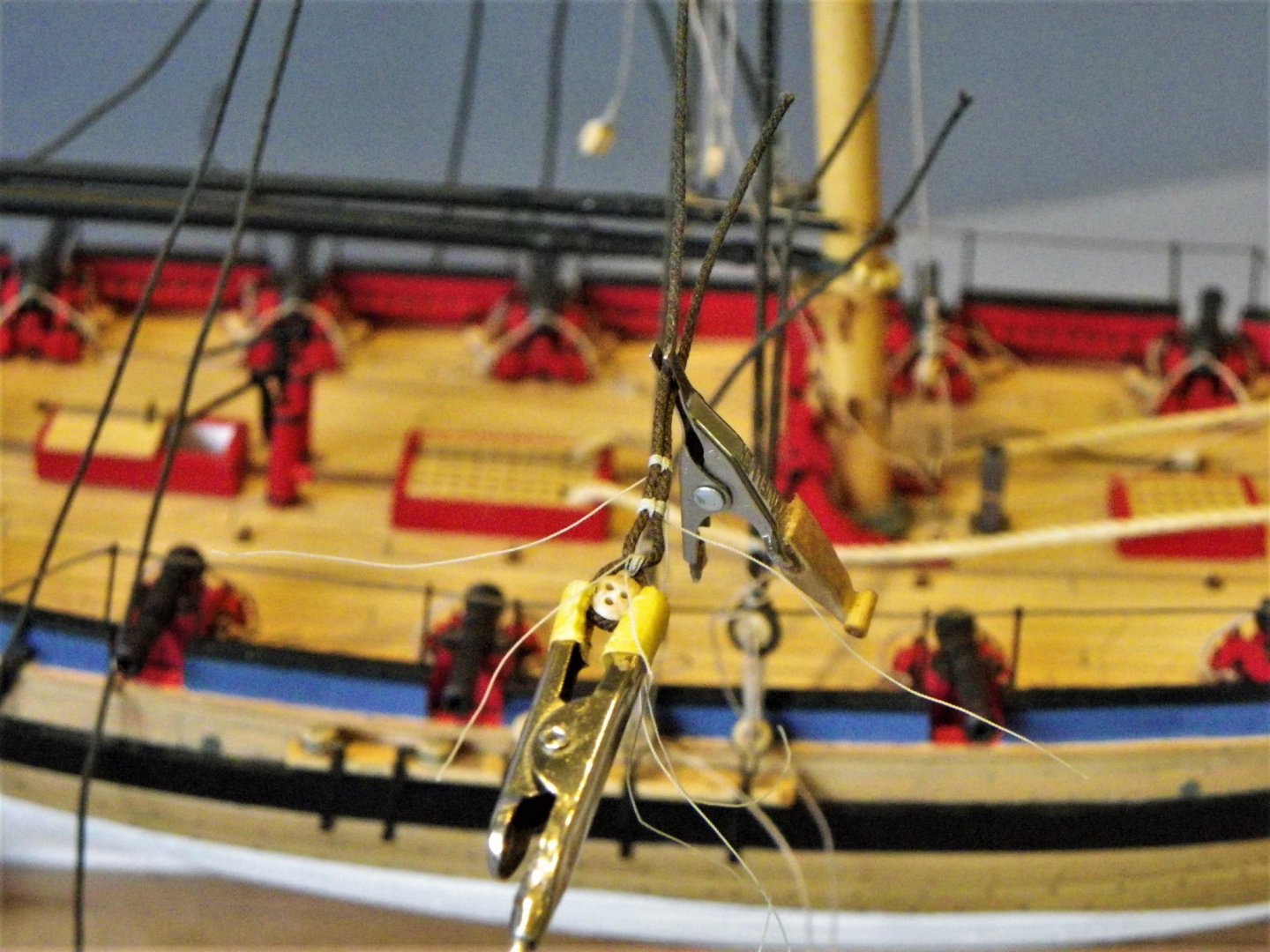
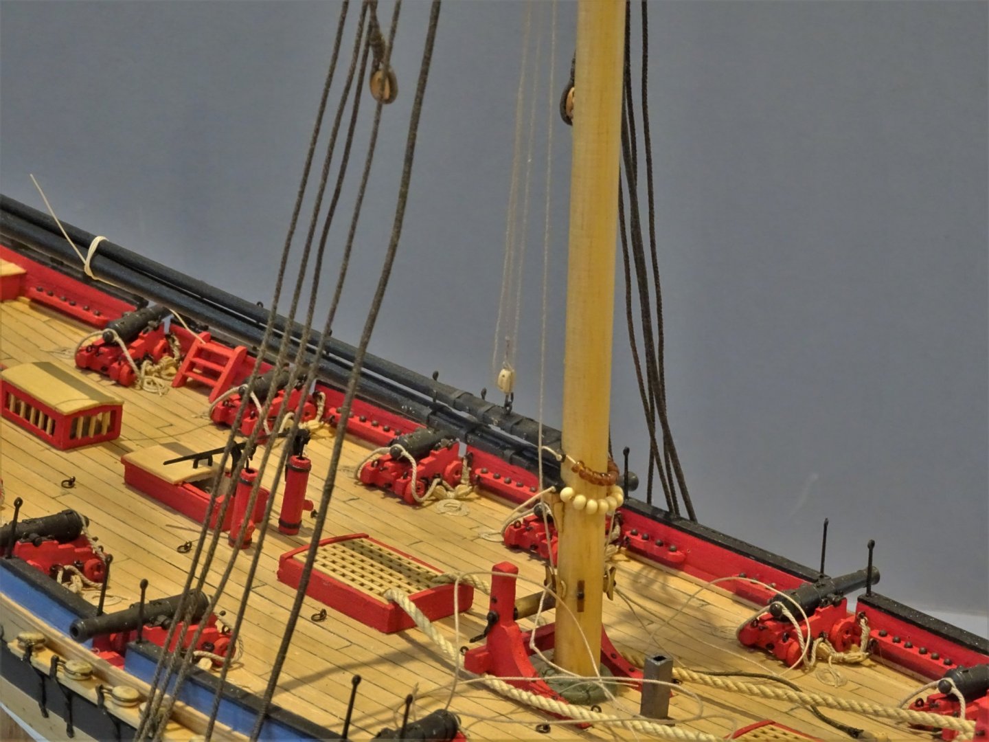
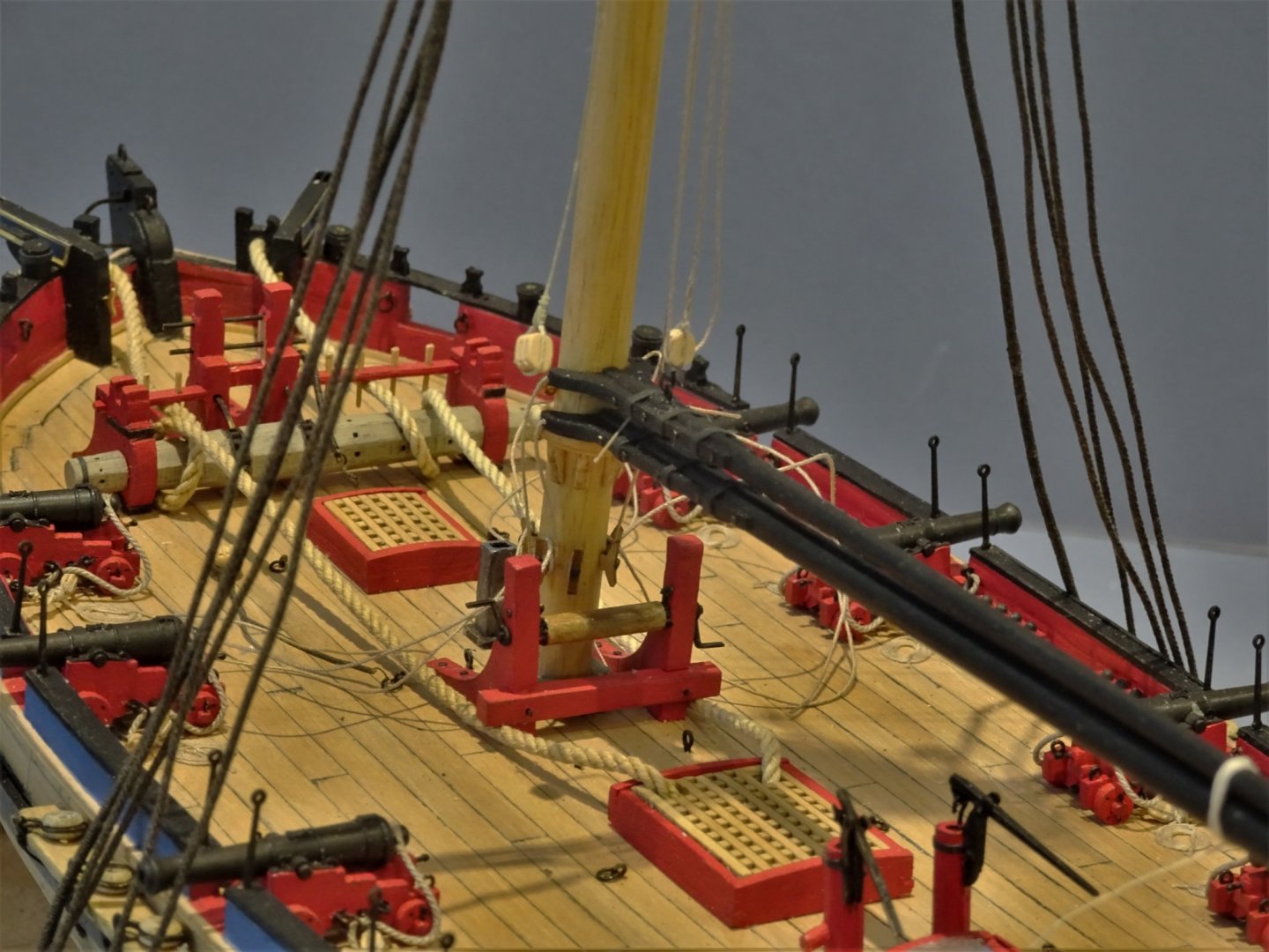
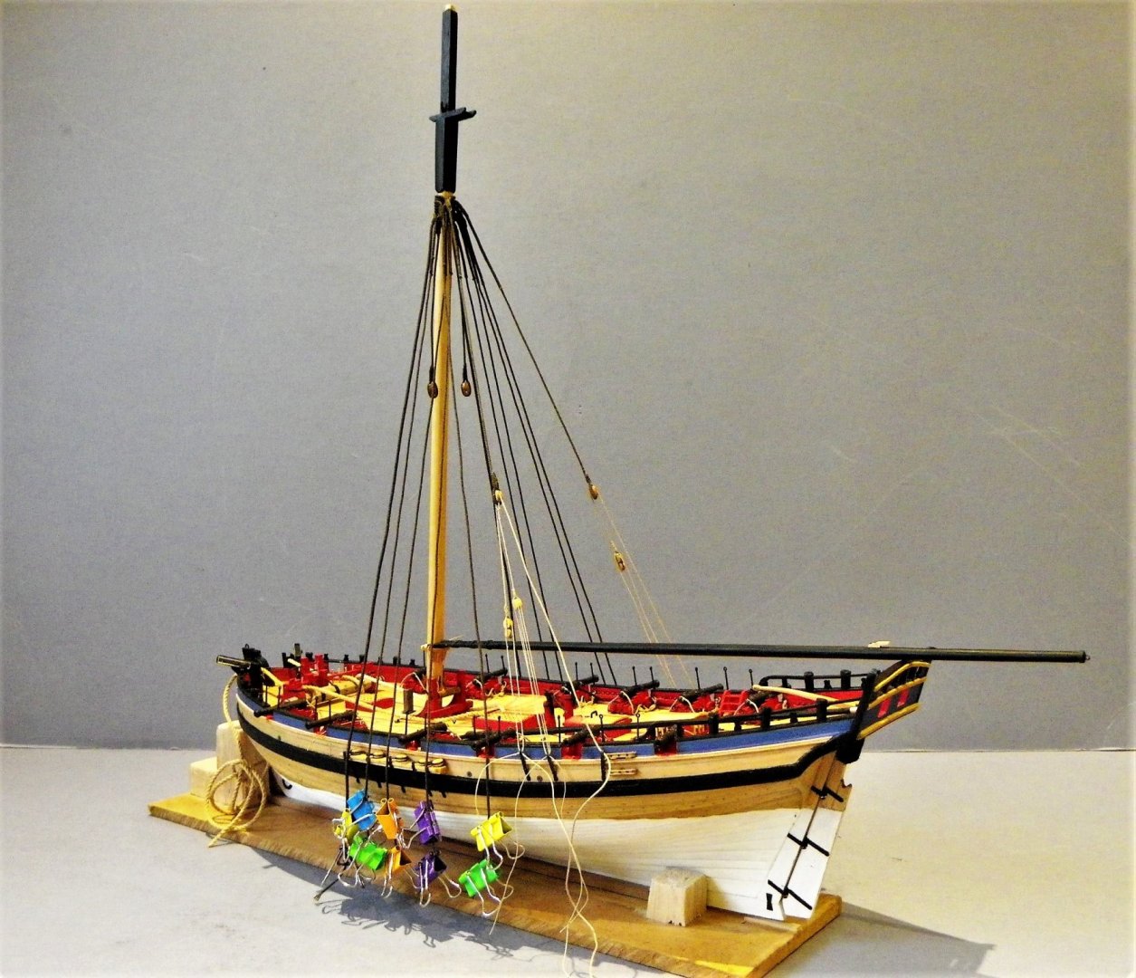
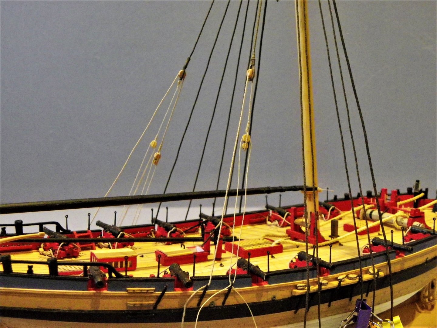
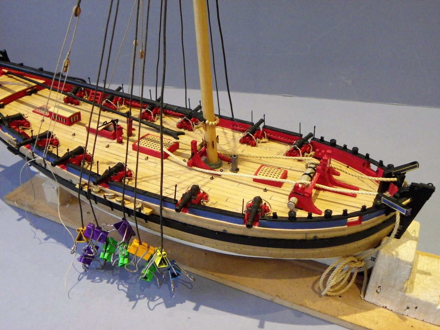
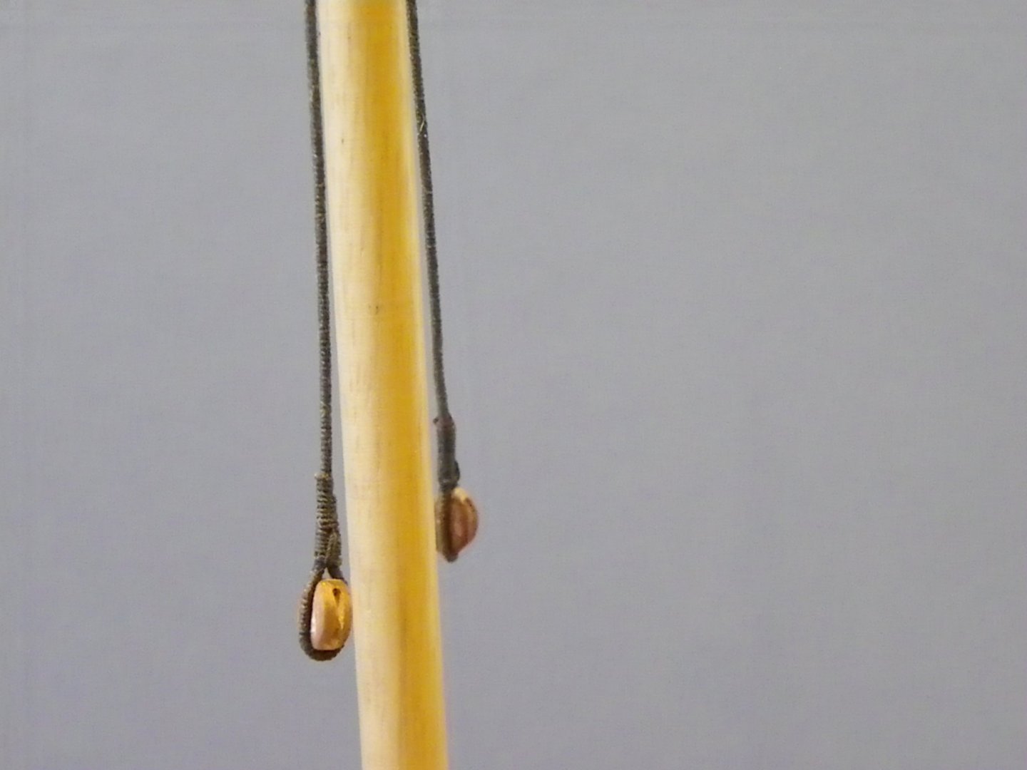
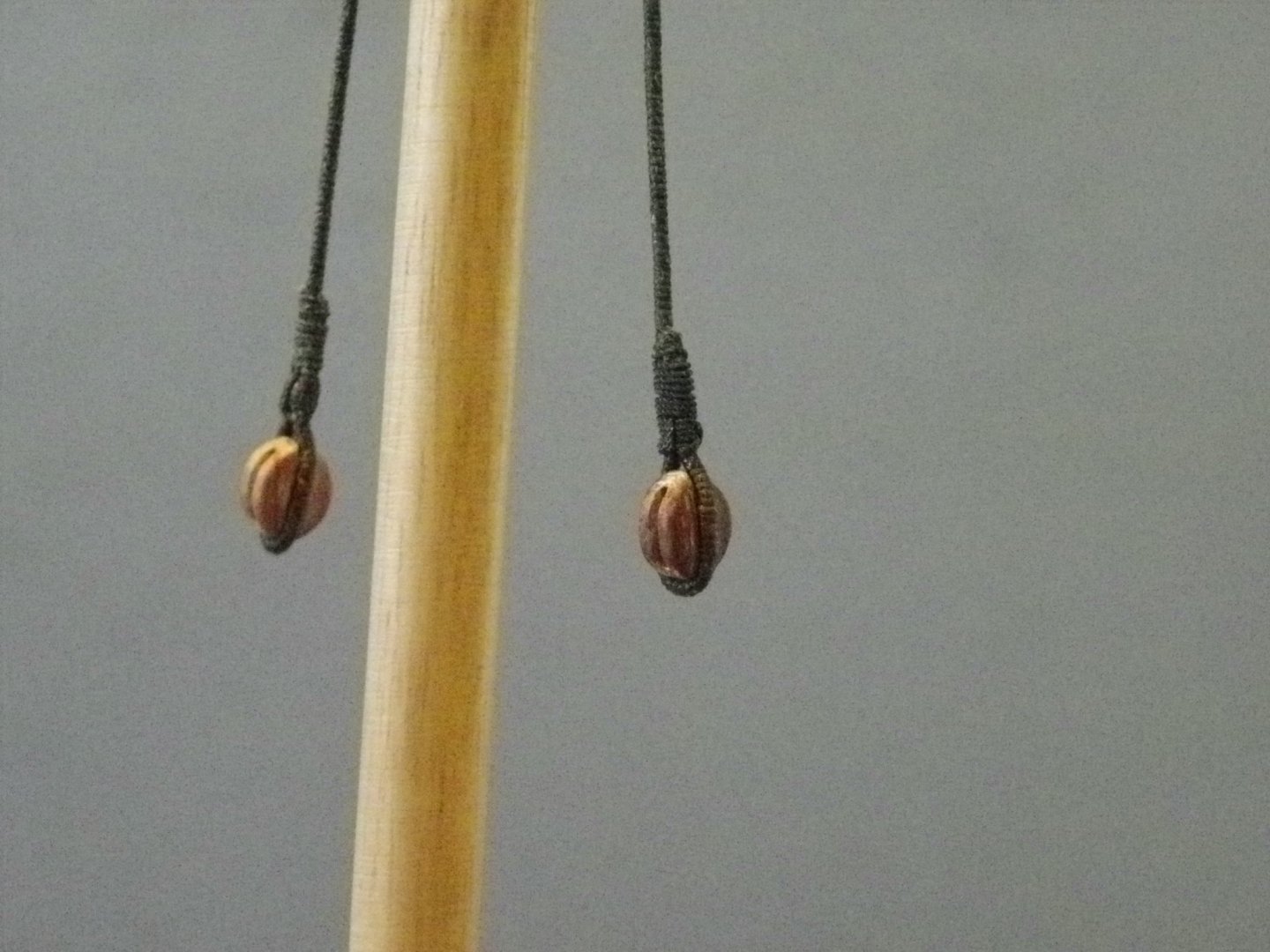
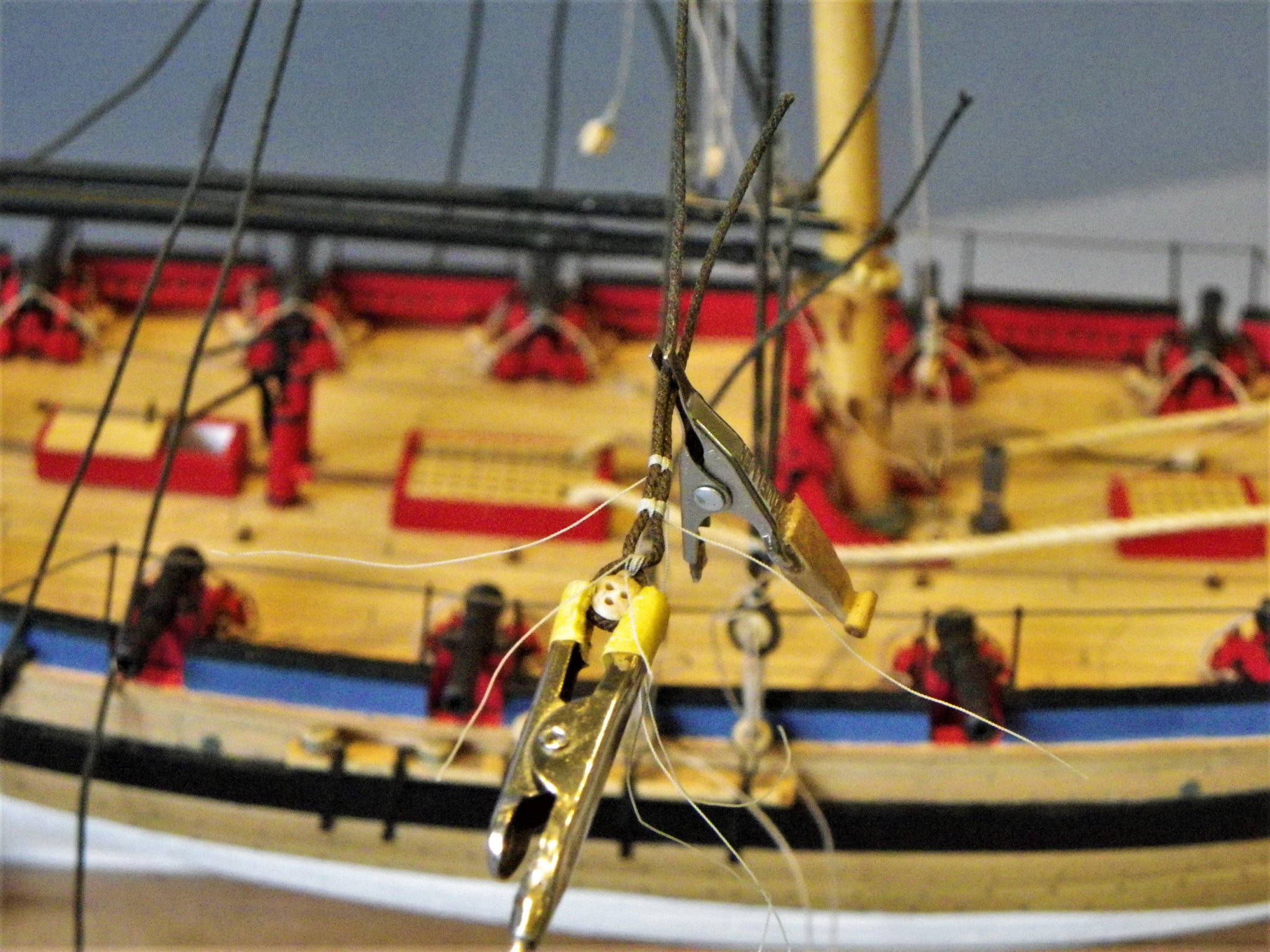
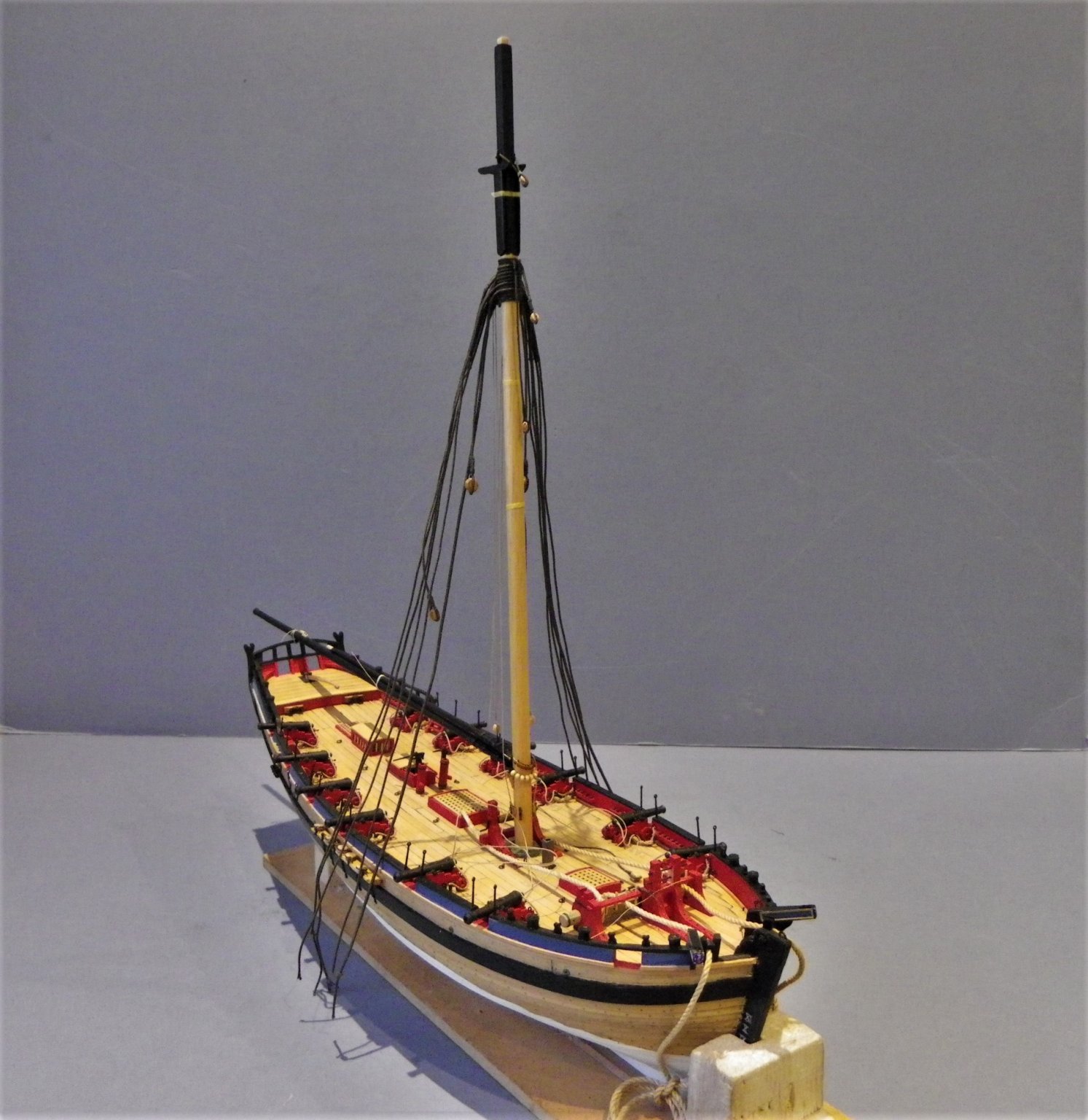
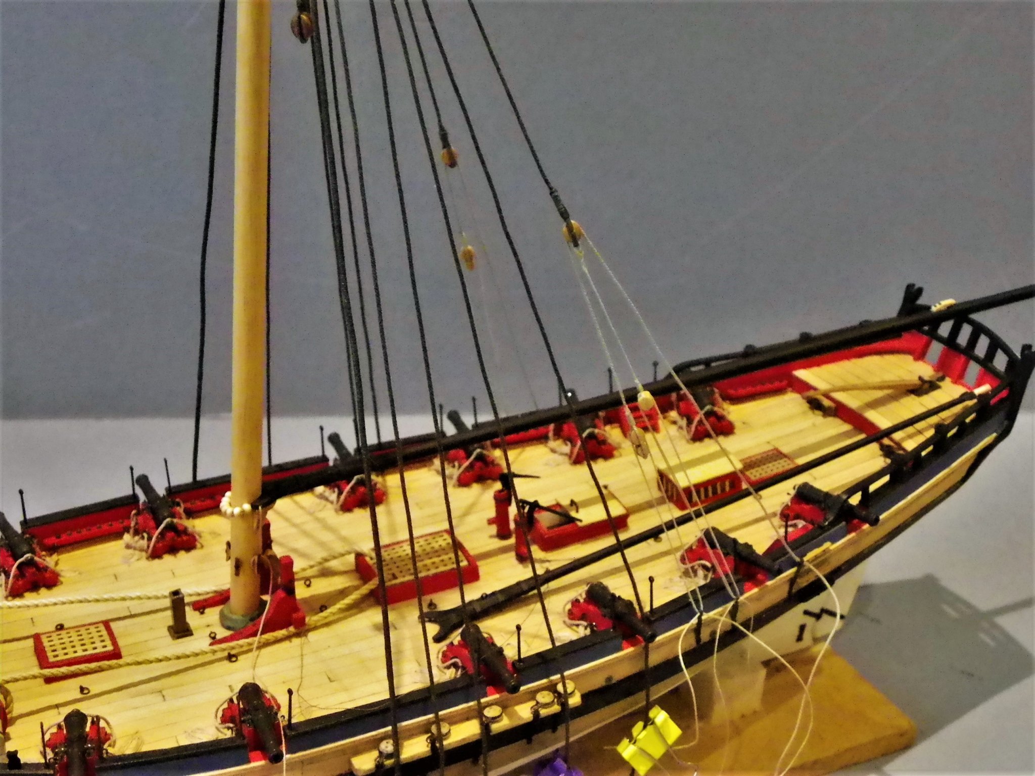
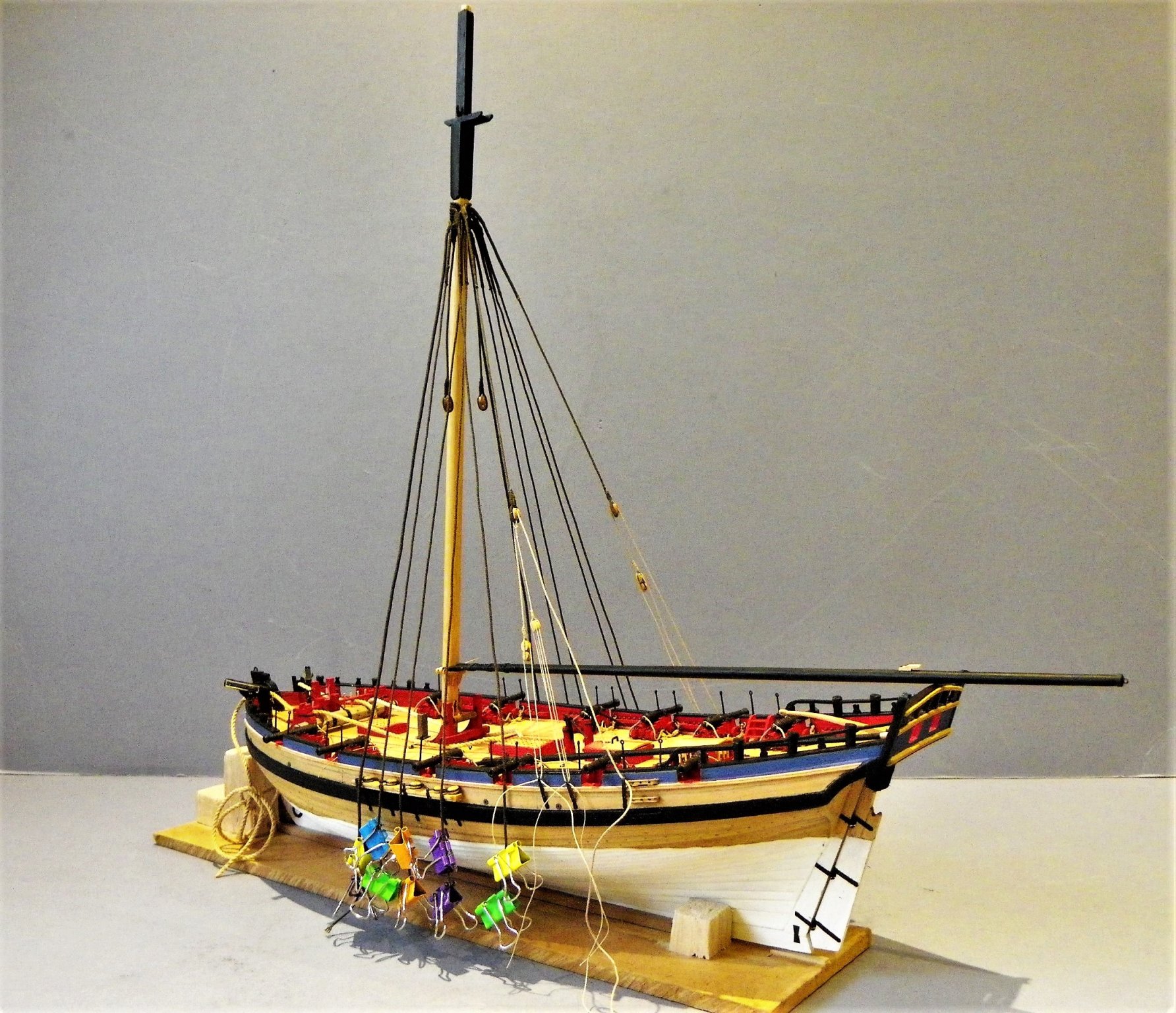
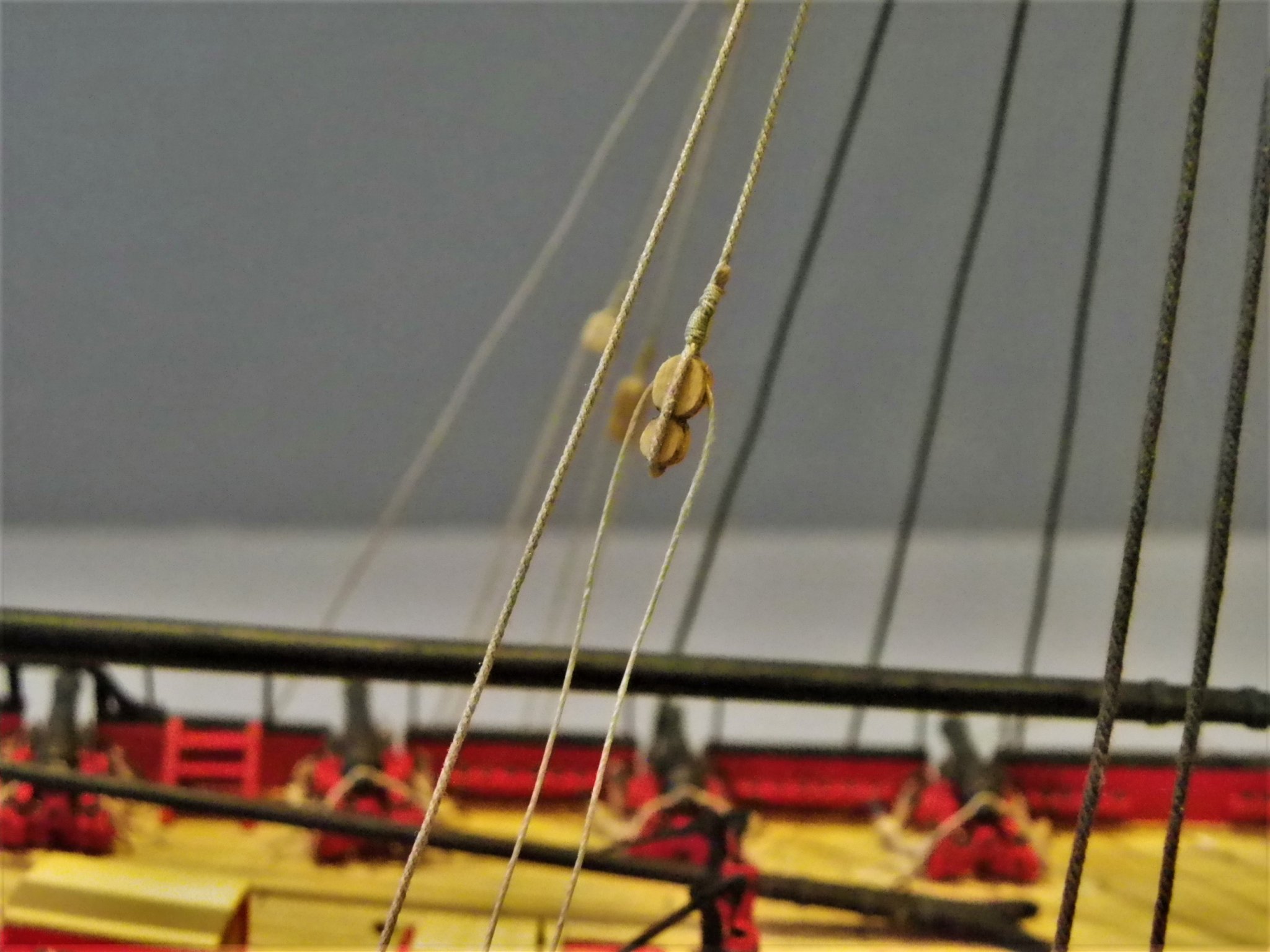
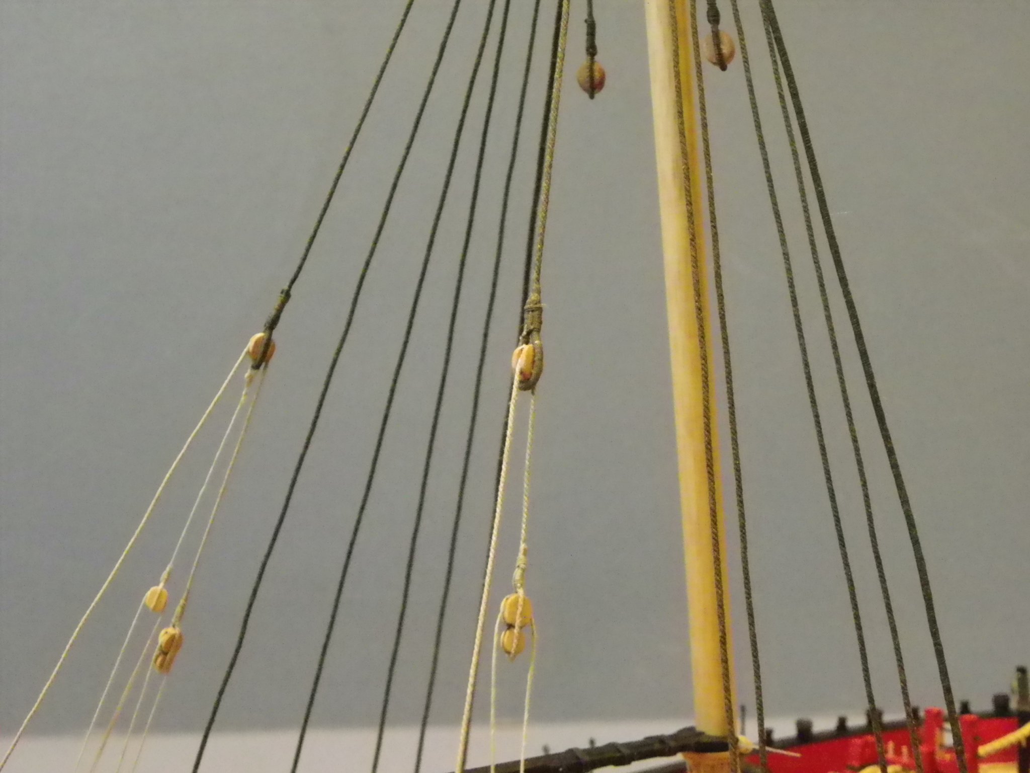
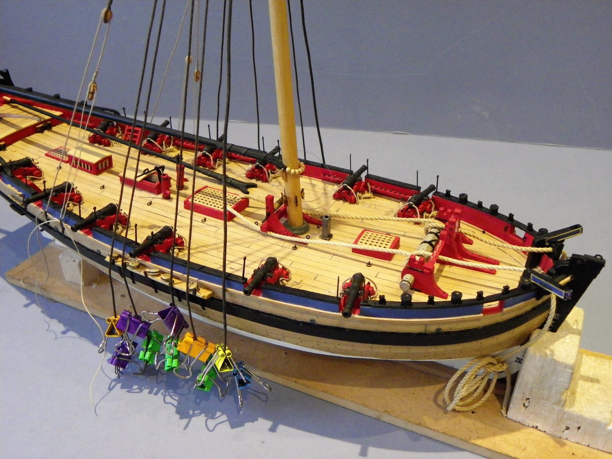
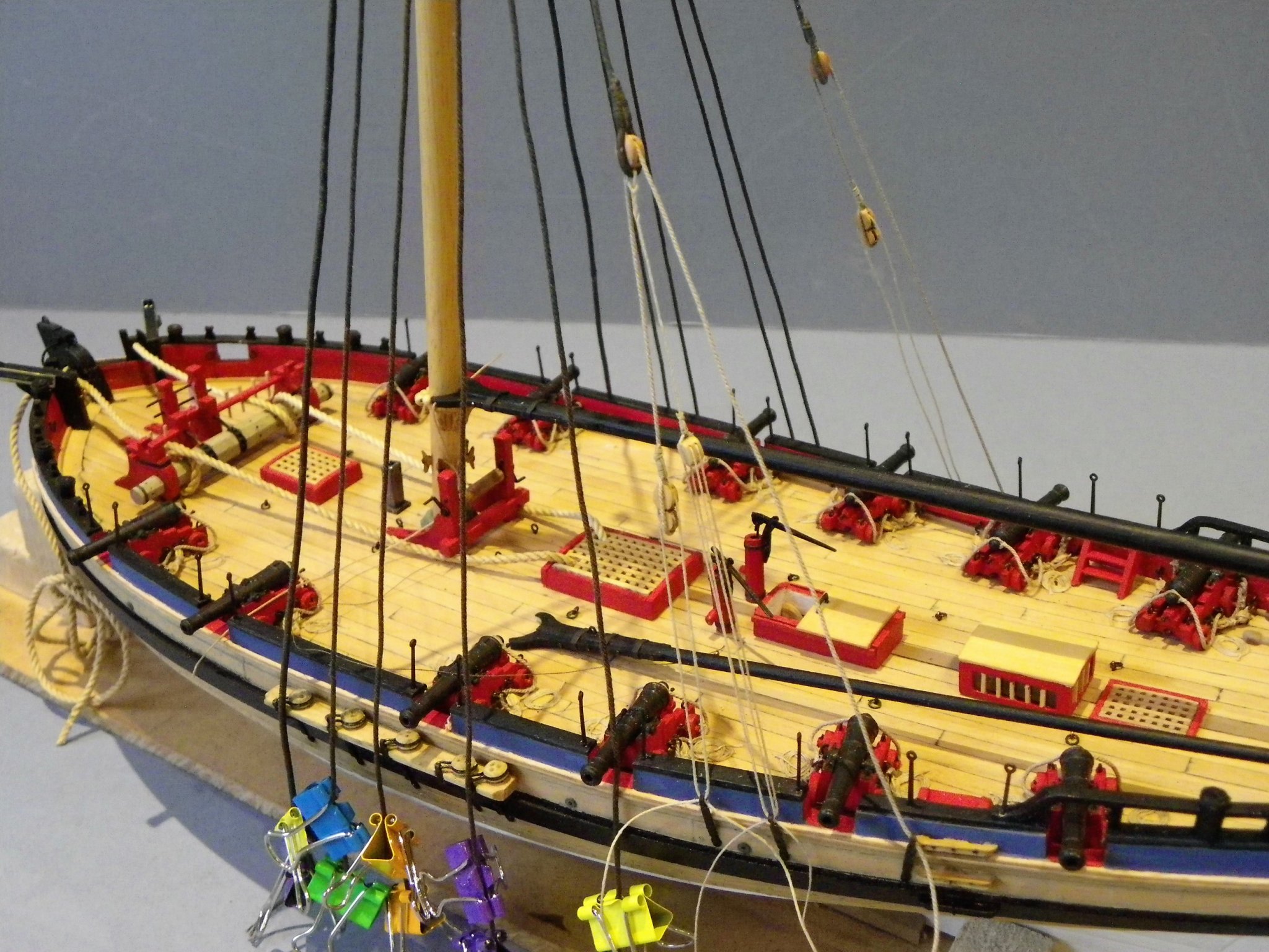
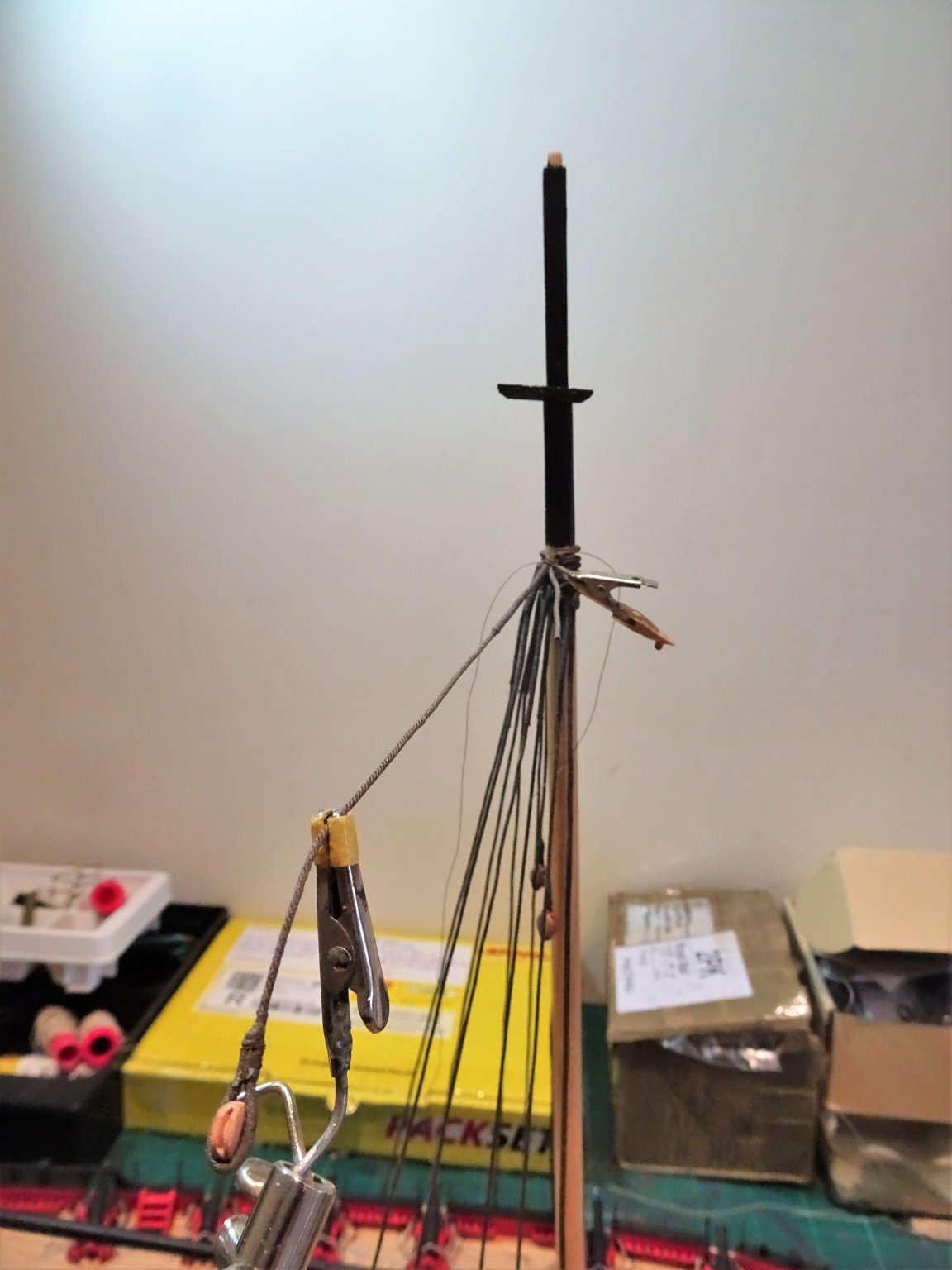
Post 60 Continuing the mast rigging. With the Standing backstay discarded I move onto making the Pendents for the Running Backstays. 4390 Seizing the pendent around the 5mm block, the stropping is also served using 0.1mm ø Morope. At least this can be done off-model. Around the masthead and for several feet the line is served. 4393 Having to seize the pendent on the model makes getting a matched pair a little more tricky, and the higher up you get the more tired your arms. 4396 For the second pendent I levelled the drop before seizing. I can now test out the standing part of the running Backstay. 0169 For this I am using Syren 0.63mm line and a 9/32nd Fiddle block also from Syren. The standing part will have a thimble and hook attached to the aft iron plate, the line passes thro’ the pendent block and has the Fiddle block seized into its end. The Irving Kingman model of Alert has an additional tackle seized thro’ the strop of the Running backstay pendent. The Kingman model was featured in an NRG article in Vol 29, 1983 pp173-184. 4399 This extra tackle is also on a pendent with a 5/32nd double block seized into the end. A tackle is then set up with a single 5/32nd block hooked to the middle iron plate. This arrangement neatly uses the three iron hull plates and I am tempted to follow his example, altho’ he acknowledges that some of the reconstruction of Alert is based on conjecture and therefore possibly not accurate. 0164 So, here’s a reproduction temporarily rigged on the portside of my Alert. The other possible arrangement, and as seen on most cutters is as on the starboard side. 0170 This would follow the arrangement used on the Cole model, the Hawke model, and in the old prints kindly provided by Dirk in the previous post. 0172 So, it’s decision time, and I think I’ve done running backstays to death. 0177 I’m opting for the double tackle option, it has more interest, and as Alert was a large cutter a bit of extra tackle is probably in order. 0166 0176 I have at this stage fitted the boom, easier to get to before the shrouds are tied off. I have also fitted temporary anchor cables; it is useful to find out how the cables lie and whether they foul any of the deck fittings. B.E. 25/01/2020


- 335 replies
-
- 17
-
-
- alert
- vanguard models
- (and 1 more)
-
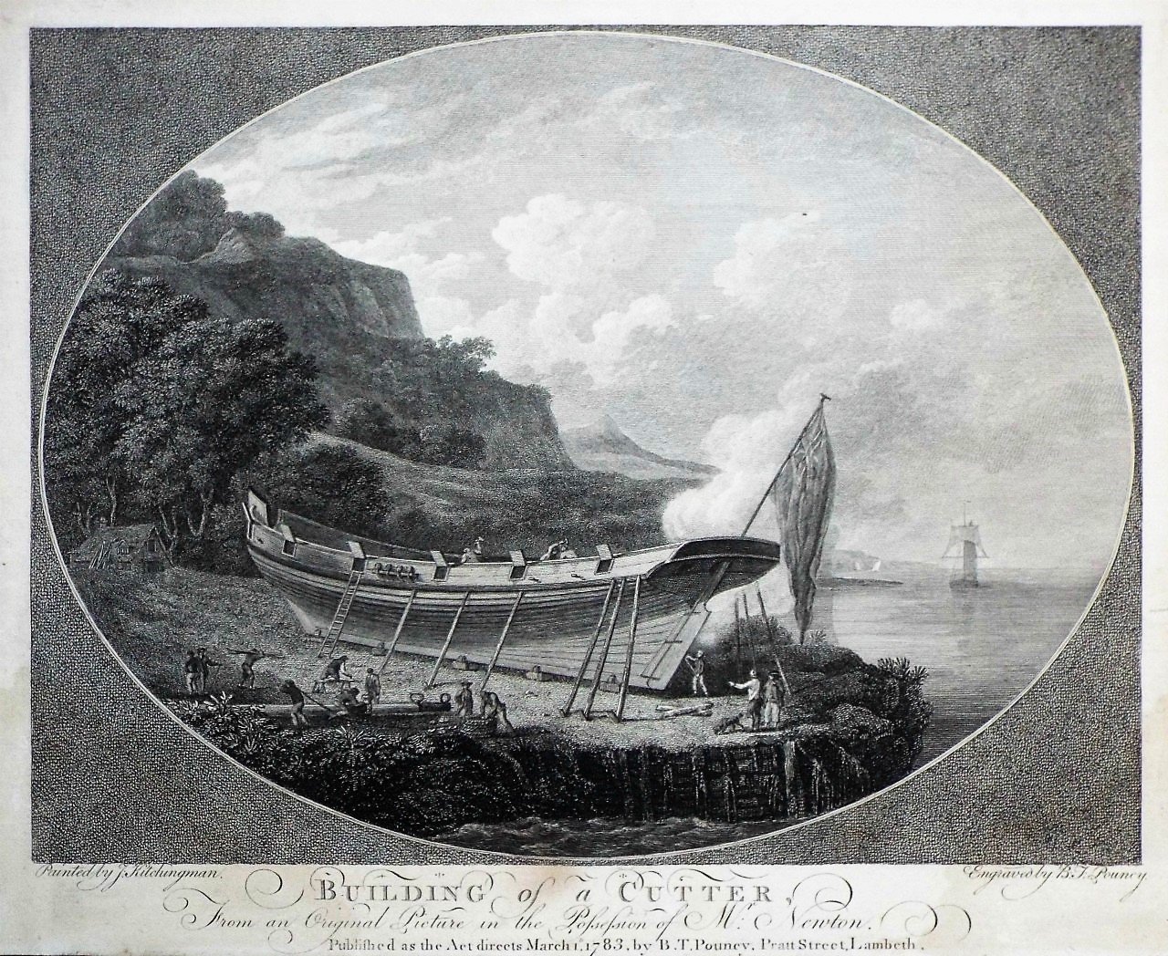
Cheers Dirk, there's a distinct lack of a deadeyed standing backstay.😉 Those prints are apparently from a set of four by John Kitchingman, (1740-1781) This one has a lot of interest too, altho' launching would have been a tricky business from that location. It seem Kitchingman was a prolific artist covering a wide range of subject matters. B.E.
- 335 replies
-
- 2
-
-
- alert
- vanguard models
- (and 1 more)
-
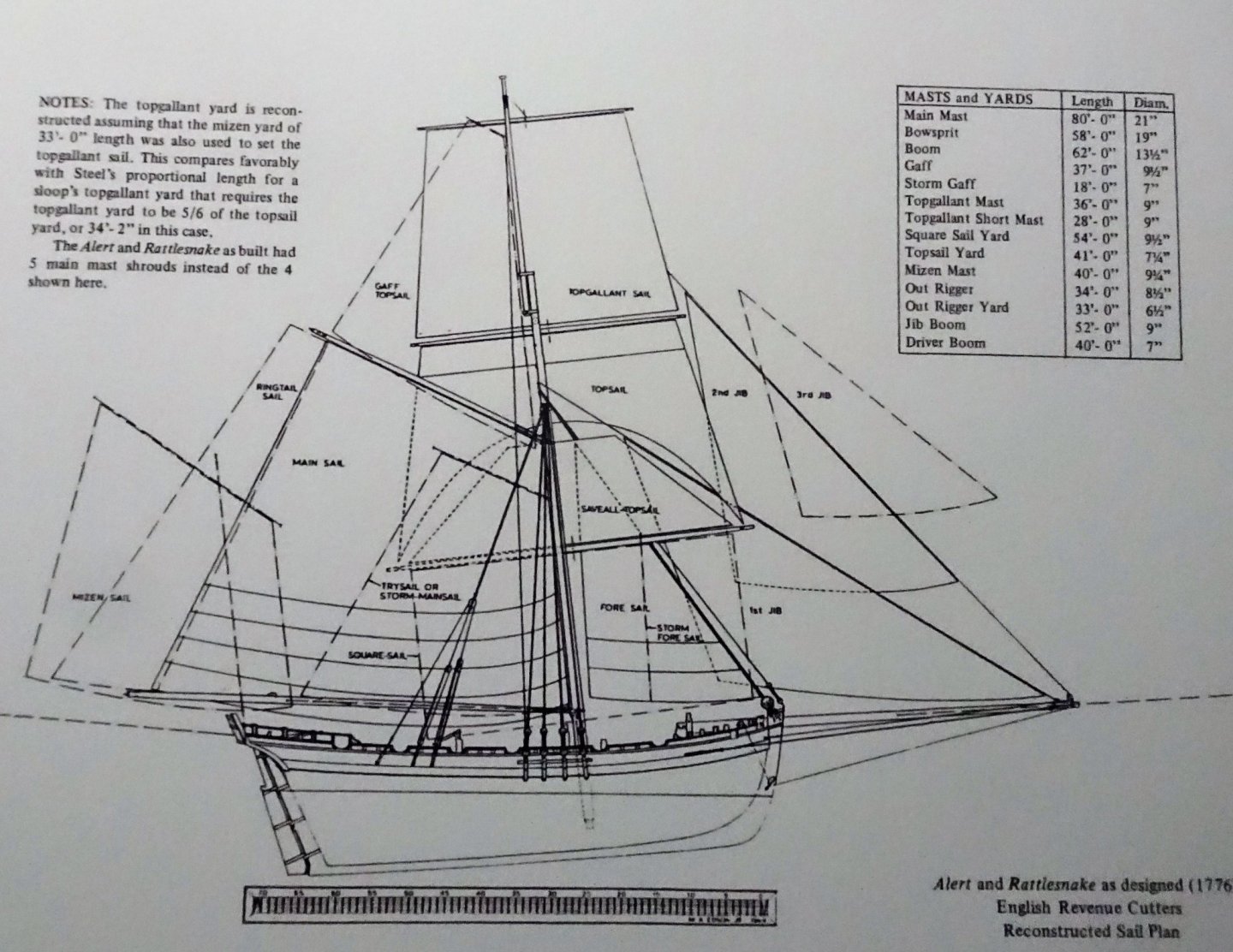
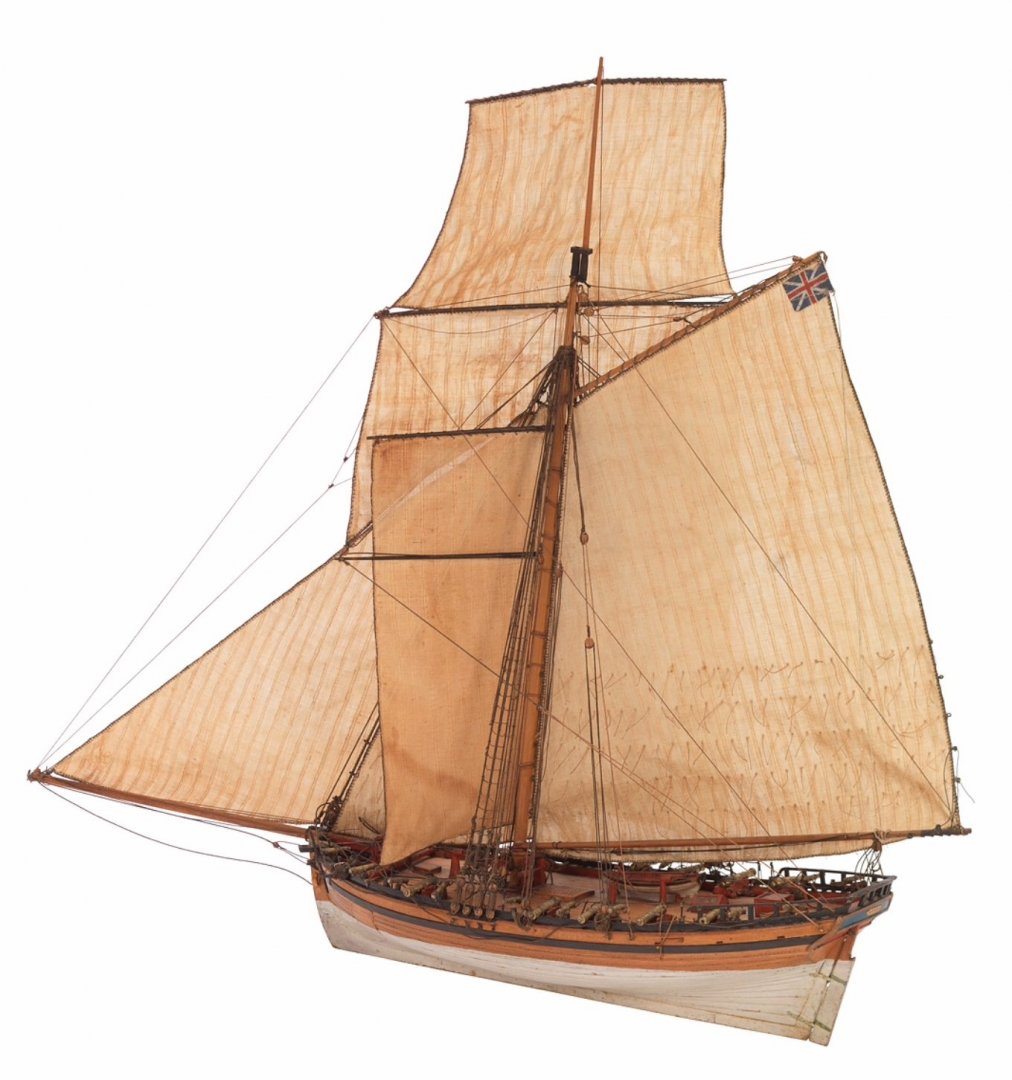
Post 59 I wrote this mainly to help clear my own mind on the way to proceed on Alert, I have struggled to accept the validity of the standing backstay as depicted in the Alert Book. The tricky business of Cutter Backstays A word about the Alert Book. Those using the Peter Goodwin Alert book as the basis of the model, as reflected in this kit, will find there is some very confusing narrative once you proceed beyond the channel shroud rigging. In the narrative it is stated that: Contemporary evidence suggests that the Alert and Rattlesnake were modified to include a fifth pair of deadeyes either side for the standing backstay. In order to facilitate this modification the third gunport had to be moved a short distance and the channels extended. Running backstays were fitted to iron plates bolted to the ships side. In drawing H4/1 this fifth set of deadeyes is described as relating to the Main Lower standing backstay So far so good, but then……… In drawing H1 a further standing backstay is shown atop the other rigging running to the first iron plate and fitted with deadeyes. Above this a running backstay pendent is shown with tackles fixed to the two aft iron plates. When we come to the detail shot of the mast head in drawing H22/1 things change. Here ratlines run across all five lines fixed to the channel described as shrouds. Above this is a standing backstay, something not listed in Steel’s tables. And atop this a running backstay. Note: the only reference to backstays in Steel’s tables are to standing backstays to the topgallant mast which Goodwin notes in the Alert book as a Topgallant breast backstay (not necessarily standard at this time.) It has been written about cutters of this period that there were many variations in the rigging set up, so there is probably not a clear answer. When looking at the Alert there are several versions, and I have looked at them all. The versions of Alert depicted by Irving H Kingman, N. Roger Cole, Peter Goodwin, all differ in rigging arrangements but none of the cutter models ancient and modern that I have looked at, have this ‘standing backstay / deadeye’ arrangement attached to the foremost iron plate. The Roger Cole model shows a familiar style of running backstay but has small stools to take the tackle set up rather than iron plates. The Kingman model shows a double tackle arrangement to the backstay, which is similar to a model circa 1790. In this case the aftermost iron plate is unused, but the Kingman model uses it for the standing part of the tackle. This is also the rigging plan used by Lennarth Petersson in his book on rigging fore and aft craft. There are other contemporary models to look at such as the well-known model of Hawke 1777. 3303 This is very much of the era of Alert and has simply the familiar style of running backstay atop the shrouds. Given the conflicting information in the Alert book, and the absence of any other examples, on balance I think I will dispense with the standing backstay and its deadeye set up and rig a running backstay only. B.E. 23/01/2020
.thumb.jpg.25772c0019a1ed1581fa2eb23577fbcc.jpg)
- 335 replies
-
- 10
-
-
- alert
- vanguard models
- (and 1 more)
-
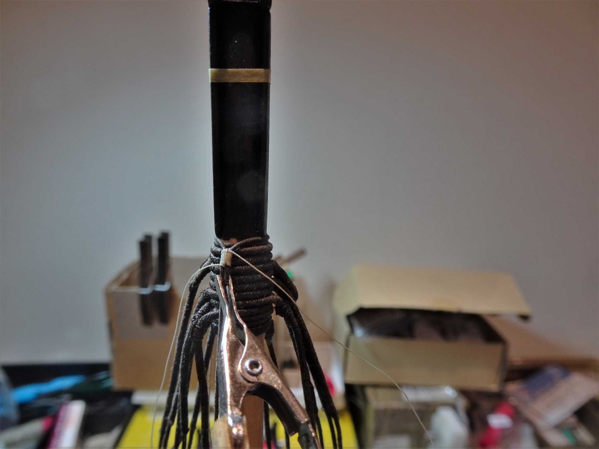
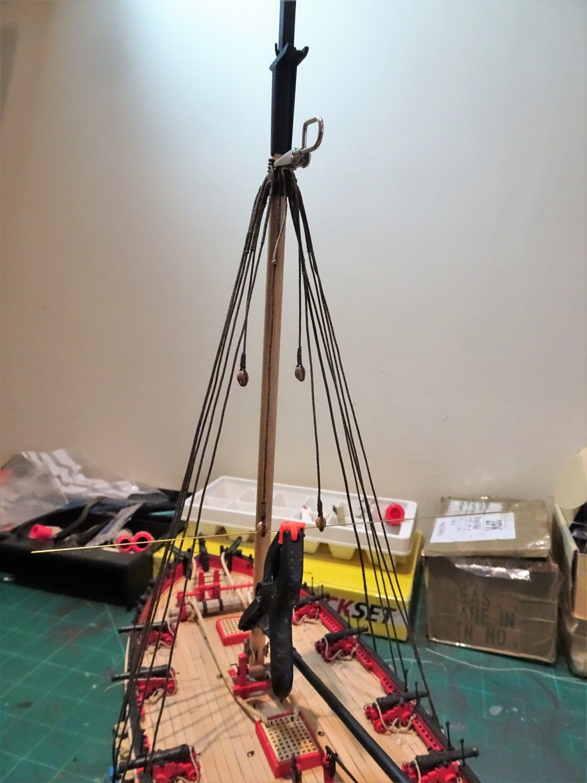
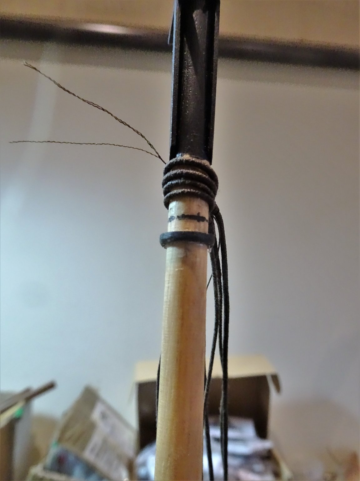
Post 58 Fitting the shrouds The biggest serving job relates to the fore shroud where the line is served overall. I used Syren 0.88mm line served with the kit provided 0.1mm line. Once served the line was re- dipped in the dye to darken it. An afternoons’ work to prepare and serve the forward pair of shrouds Port and Starboard. With the pendents and first two pairs of shrouds fitted I am in a better position to check the room necessary for the rest of the standing rigging. I had made an estimation in the position of the rigging stop to allow for increased size of rigging due to extra lines and serving but this has proved insufficient to fit it all in. The prospect of moving the stop down the mast was a little nerve jangling but with water and gentle tapping with a hammer this was achieved without drama. 4389 The top of the stop now sits 14mm below the cheeks as compared with 4mm on the kit plan. Something to bear in mind if you intend to go off piste with the rigging, as Dirk found out and noted in a previous post. 0150 It proved less irksome than I had imagined seizing the shrouds atop the stop, but I’m thankful it is only a cutter I’m rigging. 0152 There is now sufficient space to accommodate the remaining lines. 0148(2) The last line in the set along the channel is the *lower mast standing backstay, effectively an additional shroud except the ratlines don’t cross it. * Or is it – see subsequent post. 0155 0153 0156(2) After this point the rigging gets confusing which will be the subject of my next post. B.E. 22/01/20

.thumb.JPG.8d14586b425071c097b352972626419d.JPG)
.thumb.JPG.062c10f1de68679d3d92576a314d0a63.JPG)
.thumb.JPG.83d90acecdeec237cef3667f23309305.JPG)
- 335 replies
-
- 17
-
-
- alert
- vanguard models
- (and 1 more)
-
Thanks Frankie, great painting of a cutter. I can see the mainsail pressing against the Starboard running backstay, but that is a long way aft of the aftermost shroud which Steel noted as being served. Interesting thought baggywrinkles at 1:64 scale, but I think as my Alert will be bare stick, I can dispense with the torment of reproducing those.😉 Cheers, B.E.
- 335 replies
-
- 1
-
-
- alert
- vanguard models
- (and 1 more)
-
Nice first planking job Derek, a good base for the second layer. 👍 B.E.
- 725 replies
-
- 1
-
-
- vanguard models
- speedy
- (and 1 more)
-
Thanks for the insight Steve.👍 B.E.
-
Ah yes, cheers Dirk, still can’t understand why the shroud is served, but perhaps can understand why the foremost one isn’t.🙂 B.E.
- 335 replies
-
- 1
-
-
- alert
- vanguard models
- (and 1 more)
-
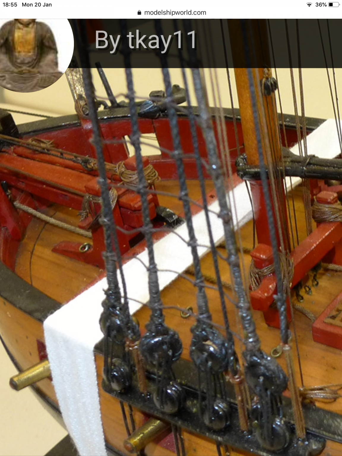
Just a follow up Dirk, looking thro’ your Sherbourne log, I came across this photo of a 1763 cutter taken by tk11. Looks to me like the aftermost shroud is served as per Steel’s writing. Doesn’t get any easier this rigging accuracy lark🤔 B.E.

-
Good to see another one started VTH, it’s been very lonely on here for the past seven months.😉 B.E.
- 436 replies
-
- 2
-
-
- vanguard models
- alert
- (and 1 more)
-
Thanks Dirk, that sounds the sensible route, fore shroud it is.😃 @ thank you Steve, I can't get my head around that one at all, on a cutter there is only the fore and aft mainsail at that point and to interfere with the backstay the main boom would have to be at 90 degrees to the hull, and would hit the running backstays to the T'gallant long before that. Another mystery to skip over I think.😉 Cheers, B.E.
- 335 replies
-
- 1
-
-
- alert
- vanguard models
- (and 1 more)
-
Thanks Dirk, I thought about removing the crosstrees, but I am wary of damaging the mast, and the cheeks are treenailed into the mast. I had already placed the stop double the kit distance down the mast, but this would not be such a problem to remove and lower further to suit the top hamper. I am exorcised at present thinking about the serving of shrouds; Steel suggests that it is the aftermost shroud that is served all over, not the foremost shroud as is normal in square riggers. SHROUDS, four pairs, are fitted and got over the mast-head, similar to those in ships. The after shroud on each side is wormed, parcelled, and served with spunyarn, down to the dead-eye. I can't quite understand this, what would chafe the aftermost shroud, which in the case of Alert would be what is called a standing Backstay. Did you have any consideration of this when you were doing Sherbourne? In the case of Alert, Goodwin notes the normal procedure of first shroud overall serving only. Any thoughts? B.E.
-
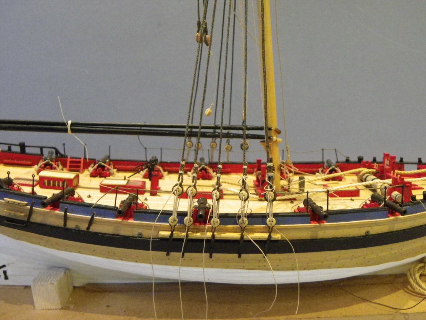
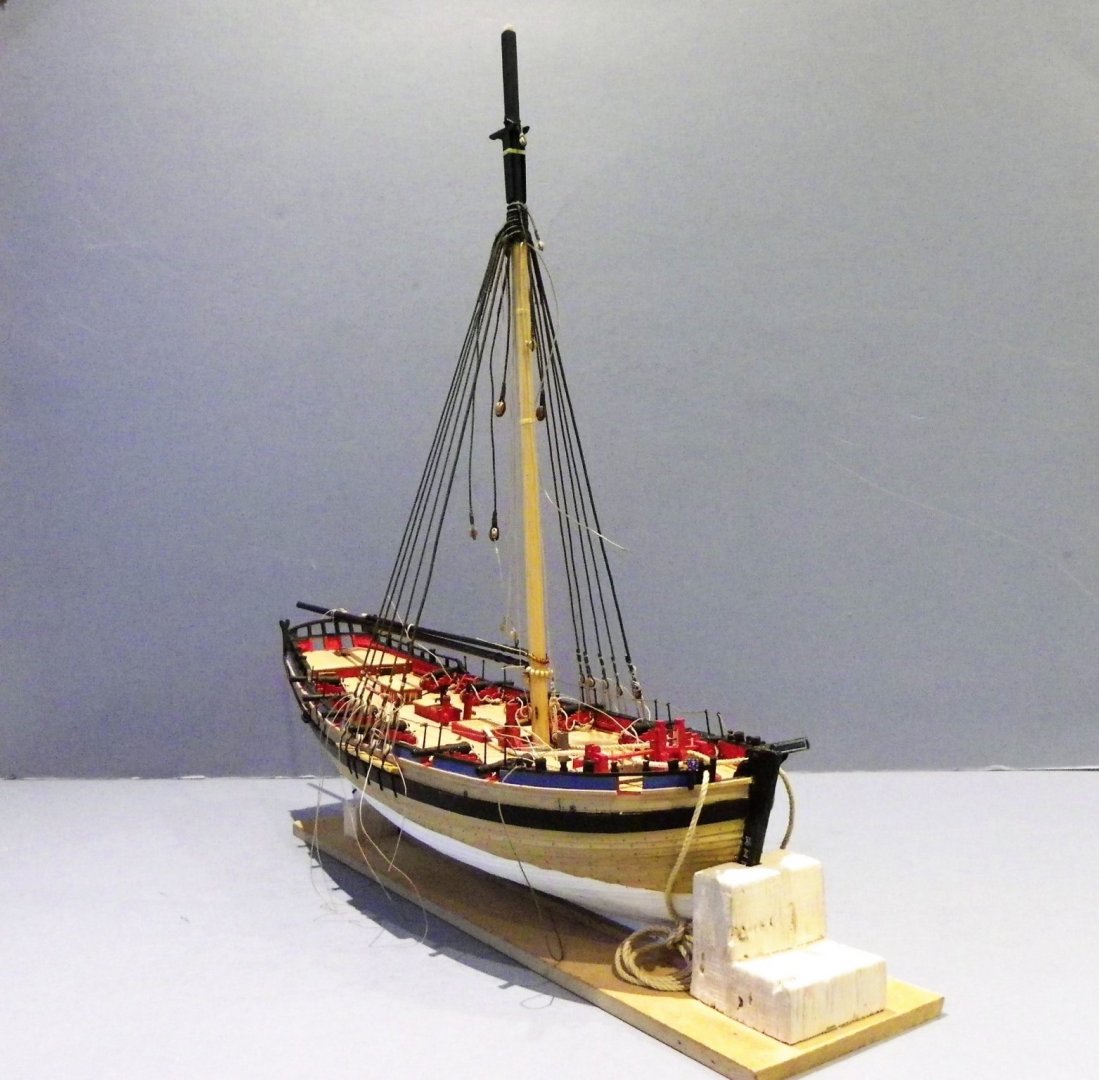
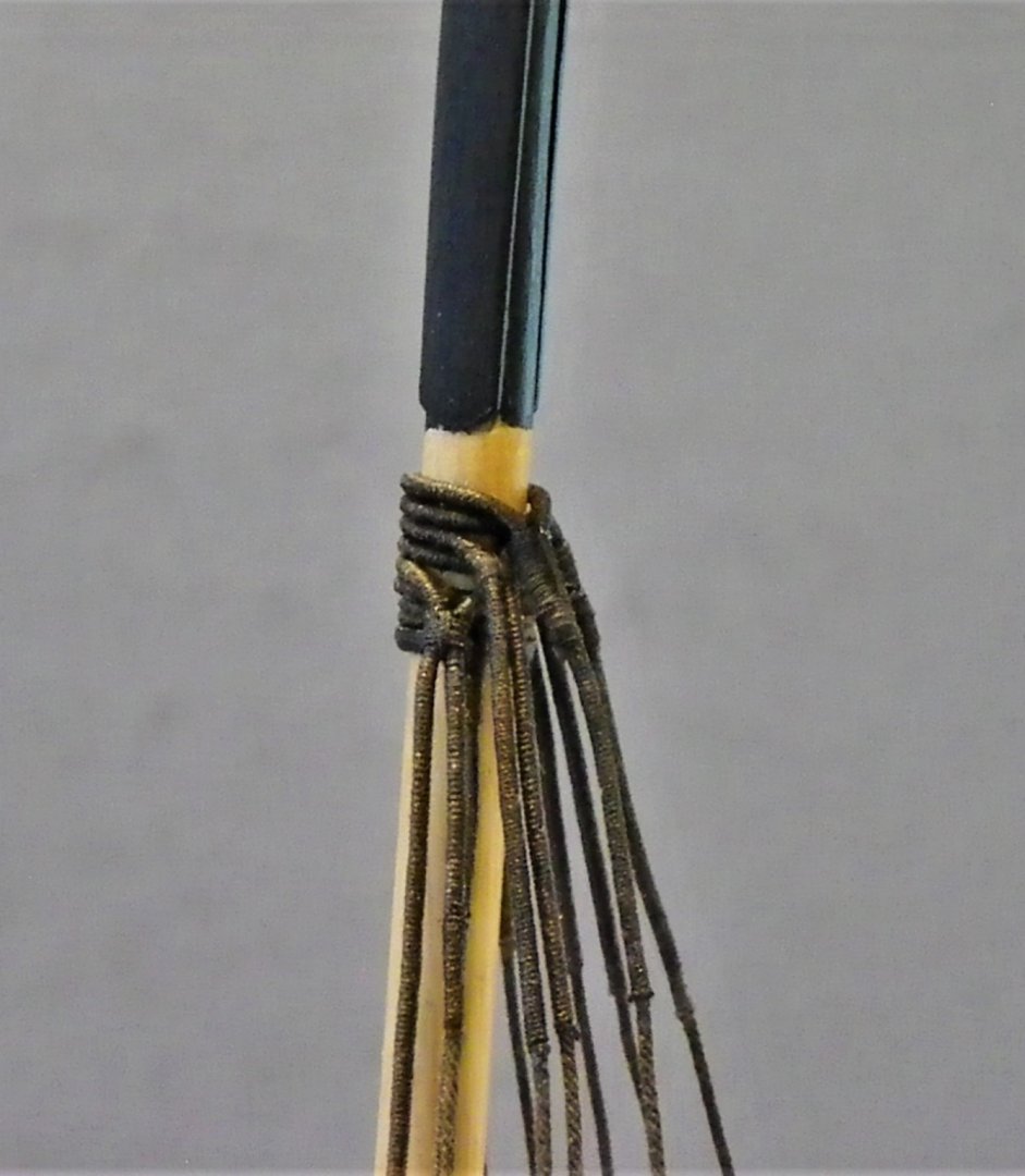
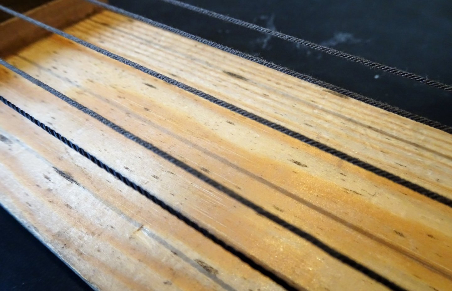
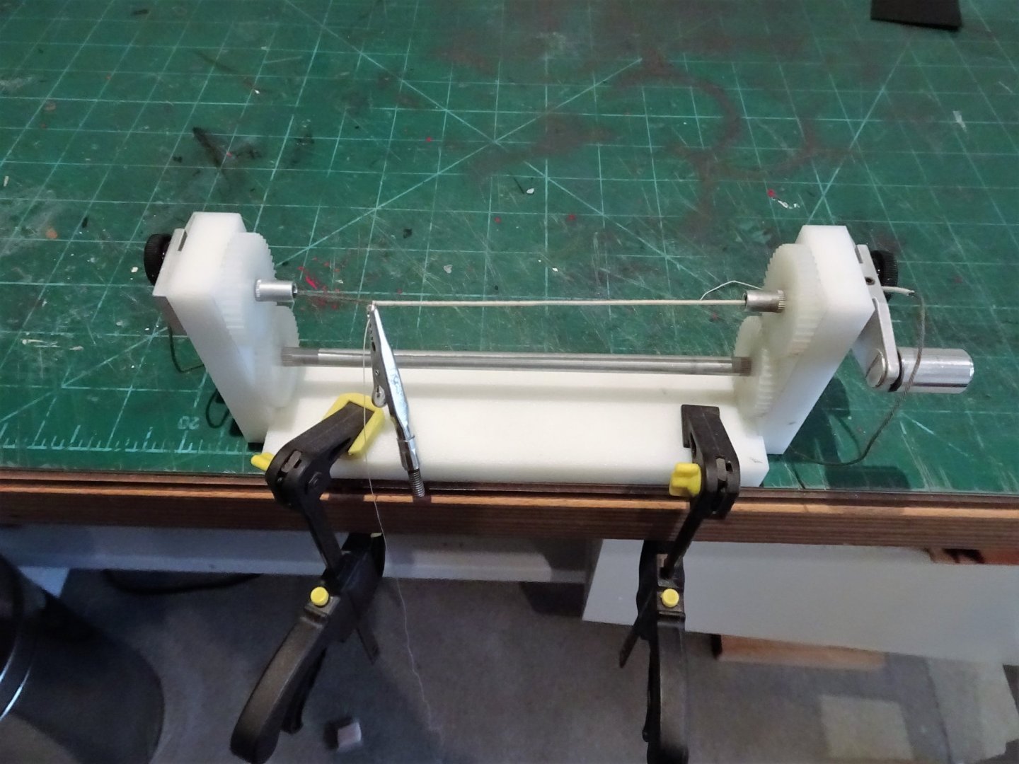
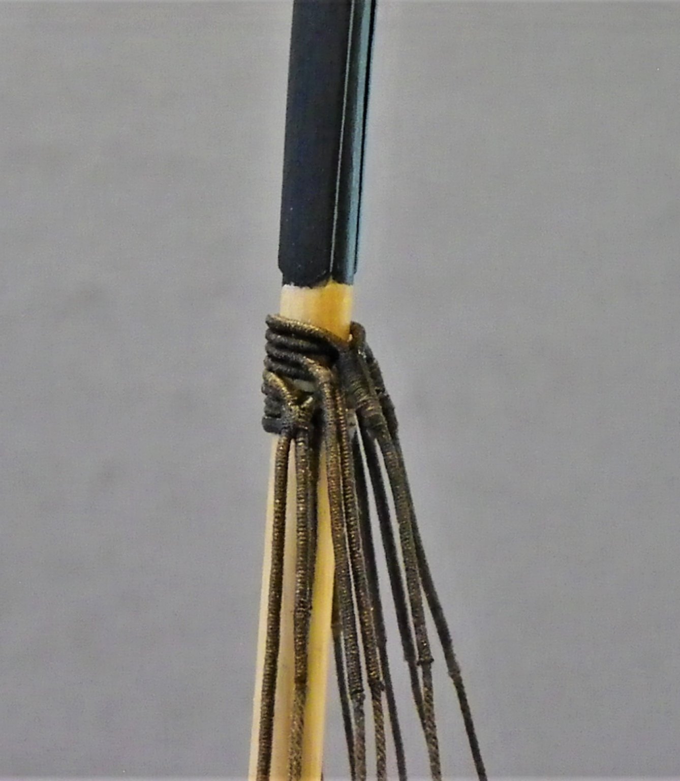
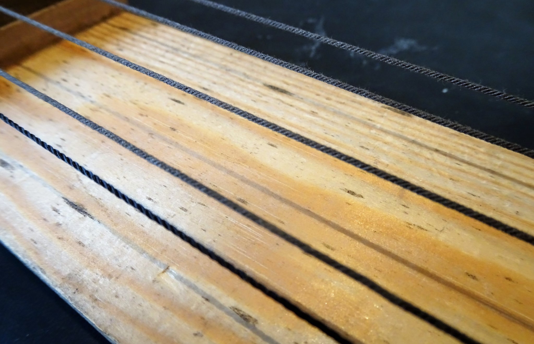
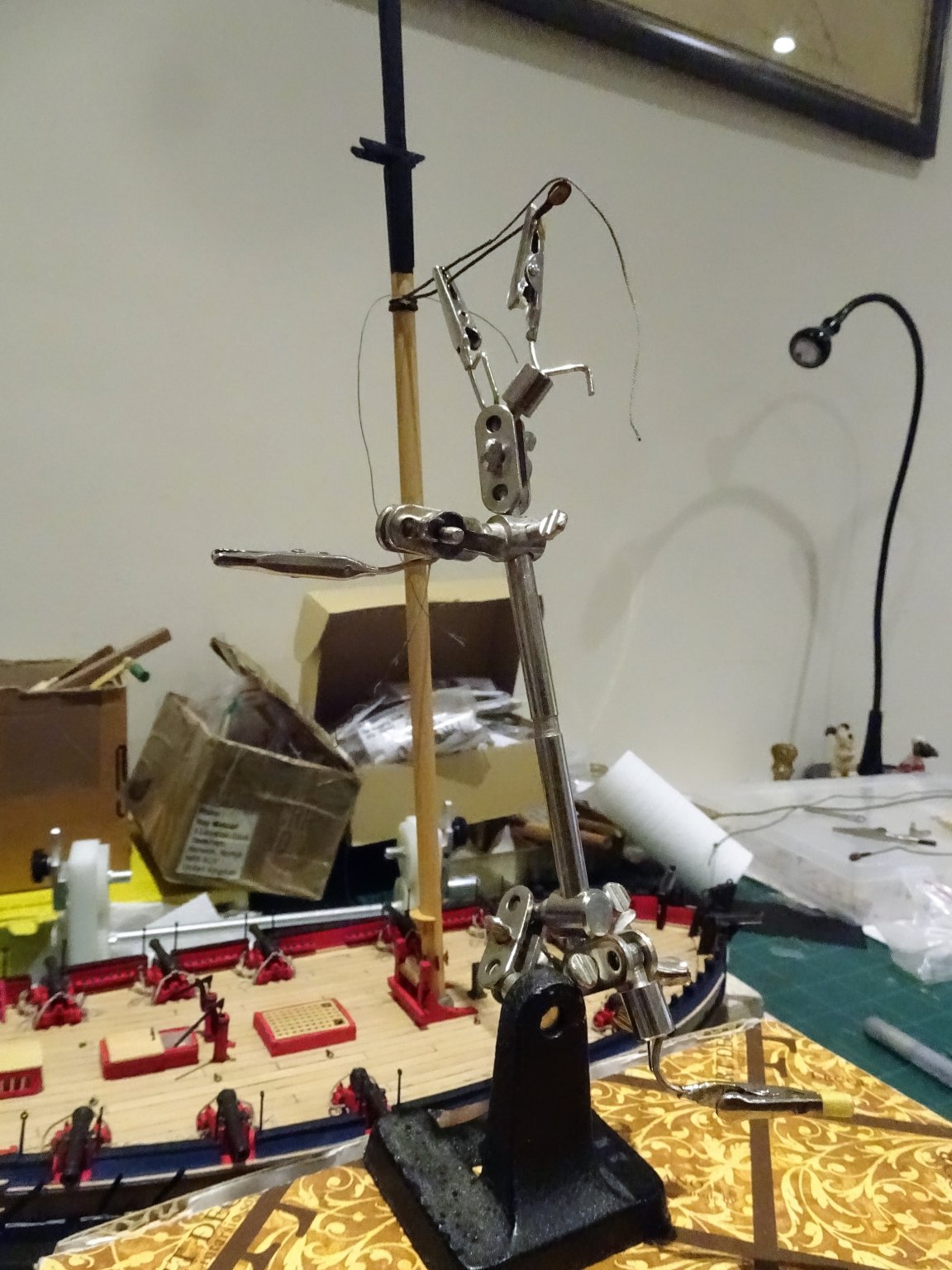
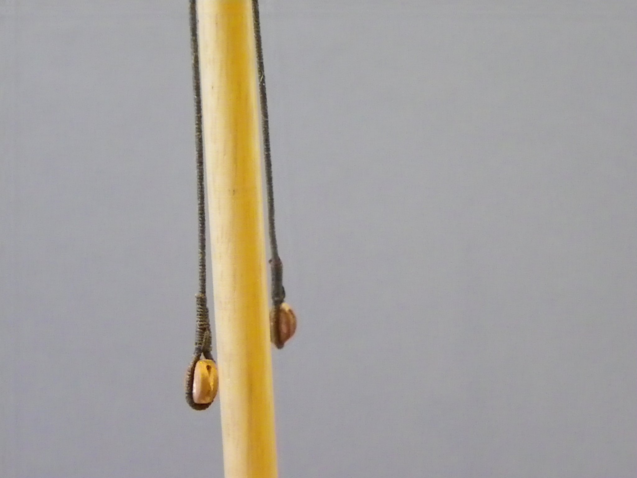
Post 57 Stepping the Mast With the mast in place the rigging can begin. I only lightly glue the lower mast in place, enough to hold it steady for rigging, but removeable if necessary. The Topmasts I don’t glue; they should hold steady in place with a close-fitting heel and mast cap. The first thing is to decide on the rigging sizes. There are differences between the indicated kit sizes, and Steel’s tables for a 200-ton cutter, slightly heavier than Alerts 185 tons. I will mostly be using Syren rigging thread supplemented by Morope polyester and possibly others for seizing and serving. For the shrouds I am using Syren 0.88mm ø line which equates to a 7” circumference line and looks right to my eye. In preparing the rigging I firstly dye the line, I use a dark Jacobean oak wood dye for this purpose, something I’ve used for many years. I then like to tension the lines for a day or so, I find they work better that way. 4379(4) This is my jig for holding the lines taut; when I come to use them, they will be tension free and easy to work. 4380 In this photo the first line is the kit supplied black 0.75mm, the others are dyed Syren 0.88mm line. Rigging starts with the pendent of tackles and shrouds. The Alert book does not cover mast pendents except in the reproduced rigging tables by Steel, where they are listed as a 6” circ. line scaling to 0.75mm ø. The other two major lines are the Mainstay and Preventer Stay, scaled at 1mm and 0.75mm in the kit. Steel gives somewhat larger sizes scaling to 1.6mm and 0.8mm. I opted for Syren 1.37mm and 0.88mm. A step backwards When I came to properly think about the rigging, I realised that I had made life difficult for myself by fixing the crosstrees at this point. An oversight caused by being long used to having the rigging sit on top of the crosstrees, and not below them. It means I cannot make the shrouds off the model and slip them over the mast head as I did with Pegasus. Not too much of an issue if the rigging is to be basic and simply slipped around the mast and round seized, but when served lines are used and more attention to the seizing form is required it can be a tiring process. It’s been three years since I rigged a model, so I’ll do a trial with the pendents of tackles, these are first over the masthead. 4383 For the pendents I used Syren 0.66mm line served with the kit provided 0.1mm natural line. The kit line is fuzz free, and I was interested to see how it performed as a serving line. The pendents are served all over and have a 15” single block spliced into the lower end. This equates to 6mm block at scale, which seems quite large, but the pendent is used for hauling heavy stuff. 4387 Fitting the Starboard pendent, were I doing the job again I would remember not to glue the crosstrees in place. 0139 At least the tackle blocks can be fitted off the model. 0147 0143(2) I could find no clear information on how far below the rigging stop the pendents hang so I have taken a punt at 80mm, about of a third of the way down to the deck. 0141(2) It looks ok to my eye, and I’ll leave them be, certainly more tiring and awkward seizing them on the model, but preferable to the risky business of trying to unglue the crosstrees. 0142(2) A lot more serving now follows as I begin the shrouds. B.E. 20/01/2020
.thumb.JPG.9a1855953fa7c02a9f3a09e1f6318c9d.JPG)

.thumb.JPG.2a4df586791710f55d4db78b976e9a7d.JPG)
.thumb.JPG.bccd55005c98b68df483812f1c61aa3c.JPG)
.thumb.JPG.c2667b29f4ba8dded2b85a78cd2579ce.JPG)
- 335 replies
-
- 20
-
-
- alert
- vanguard models
- (and 1 more)
-
You’re making a fine job of your pinnace Derek, it’s a great little kit, and I think your mini version is excellent, well done. B.E.
- 77 replies
-
- 1
-
-
- model shipways
- pinnace
- (and 1 more)
-
Thank you Derek, microporous tape is also good for stuff like canvas hatch covers, subject to size limitations. Lots of domestic items find a home in my boatyard😉 B.E.
-
Thanks Rusty, I sometimes wonder if I give too much information in the log, but I use the text as an aide memoire to myself, I still refer to my previous logs as I often can't remember how I did things.🙄 If others find this stuff of use all the better.😃 Cheers, B.E.
- 335 replies
-
- 5
-
-
- alert
- vanguard models
- (and 1 more)
-
Looks good to my eye Vane, well done. 👍 B.E.
-
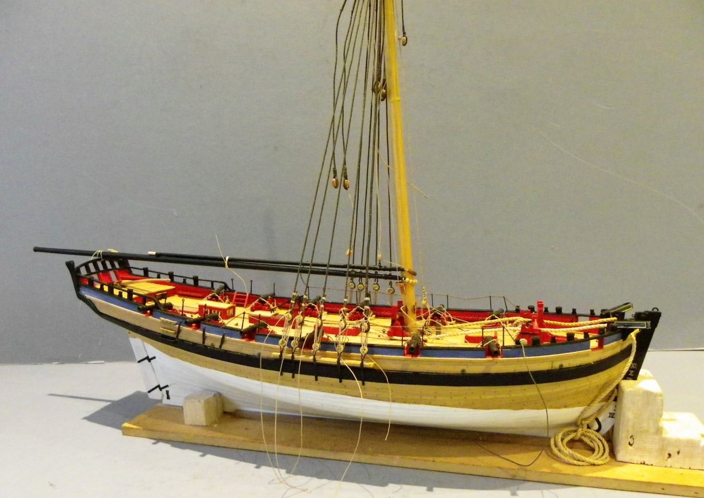
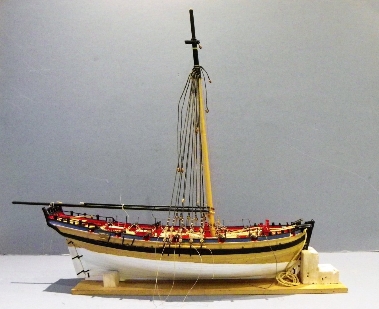
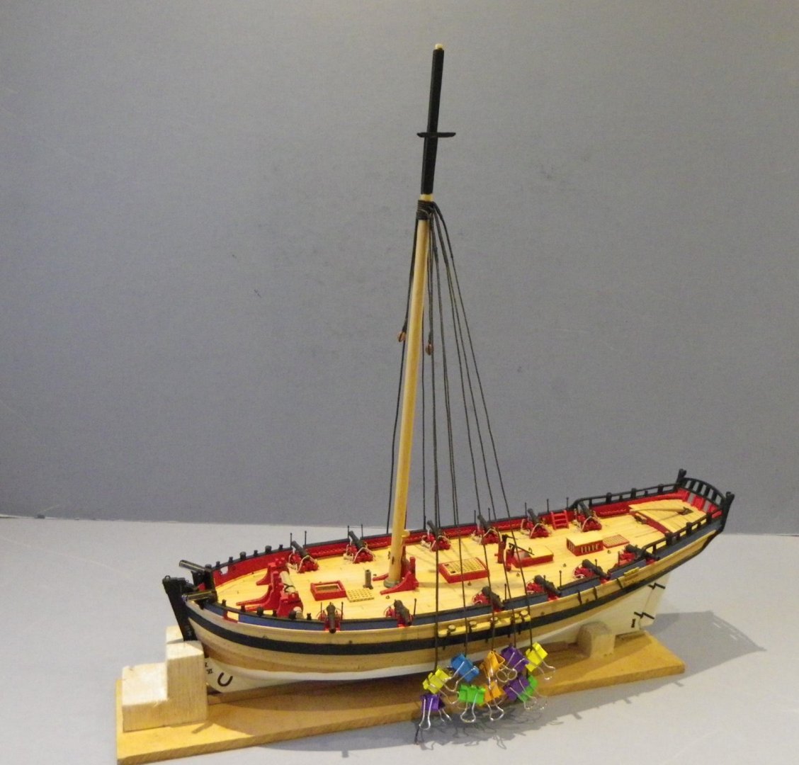
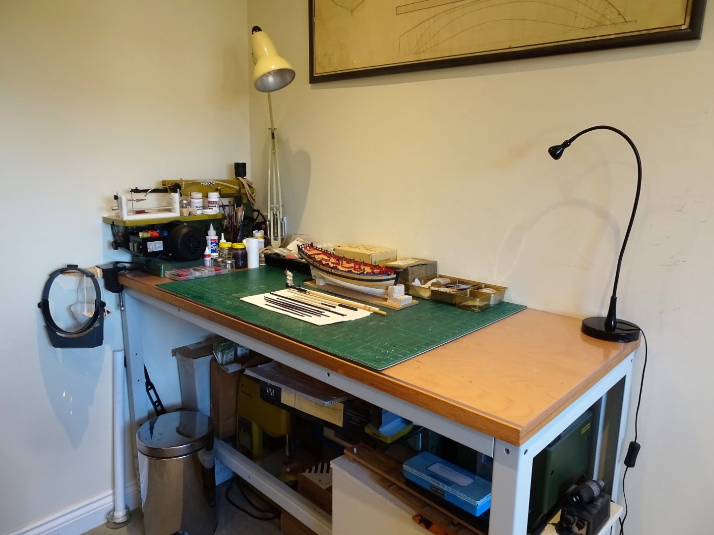
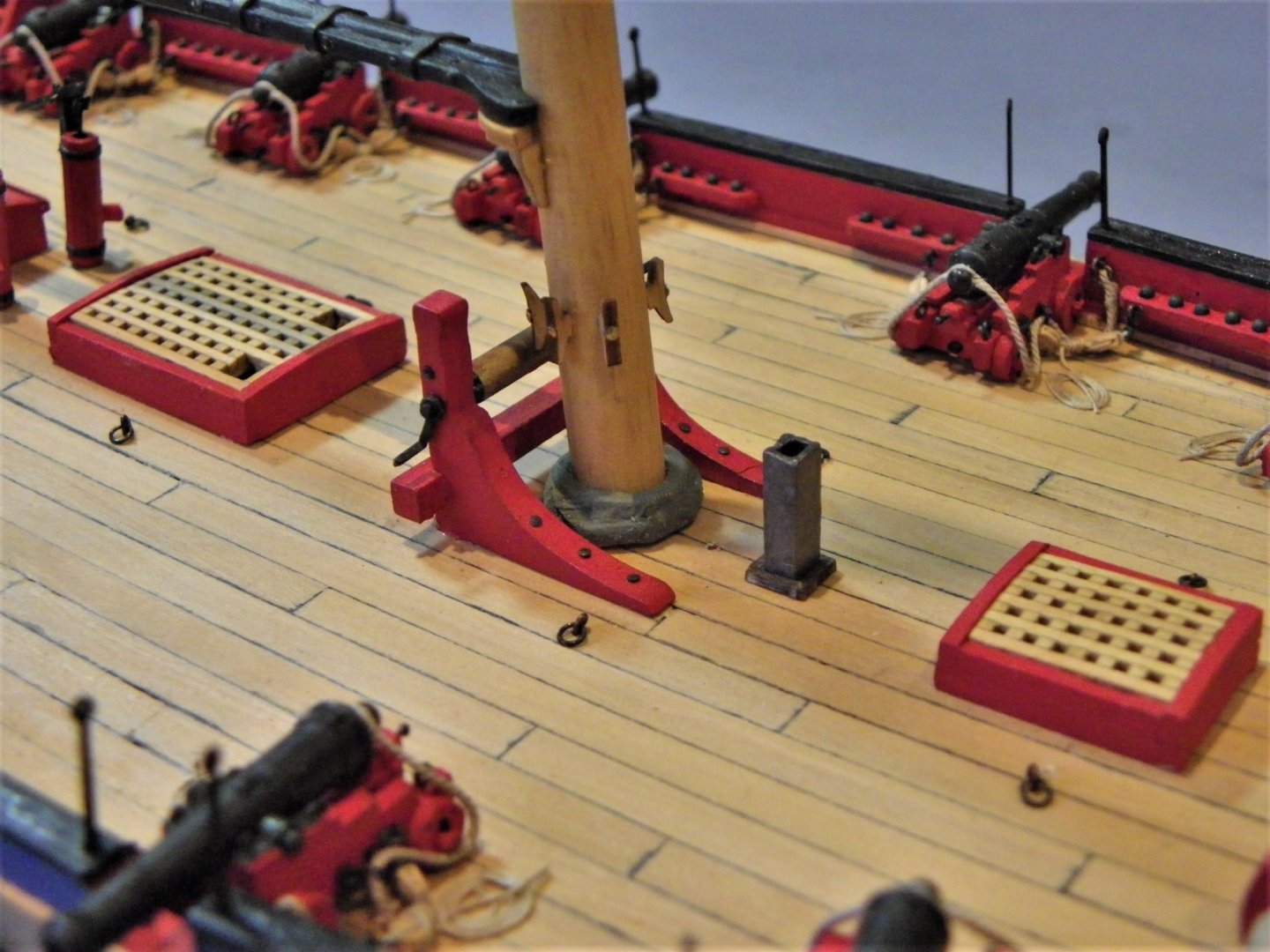
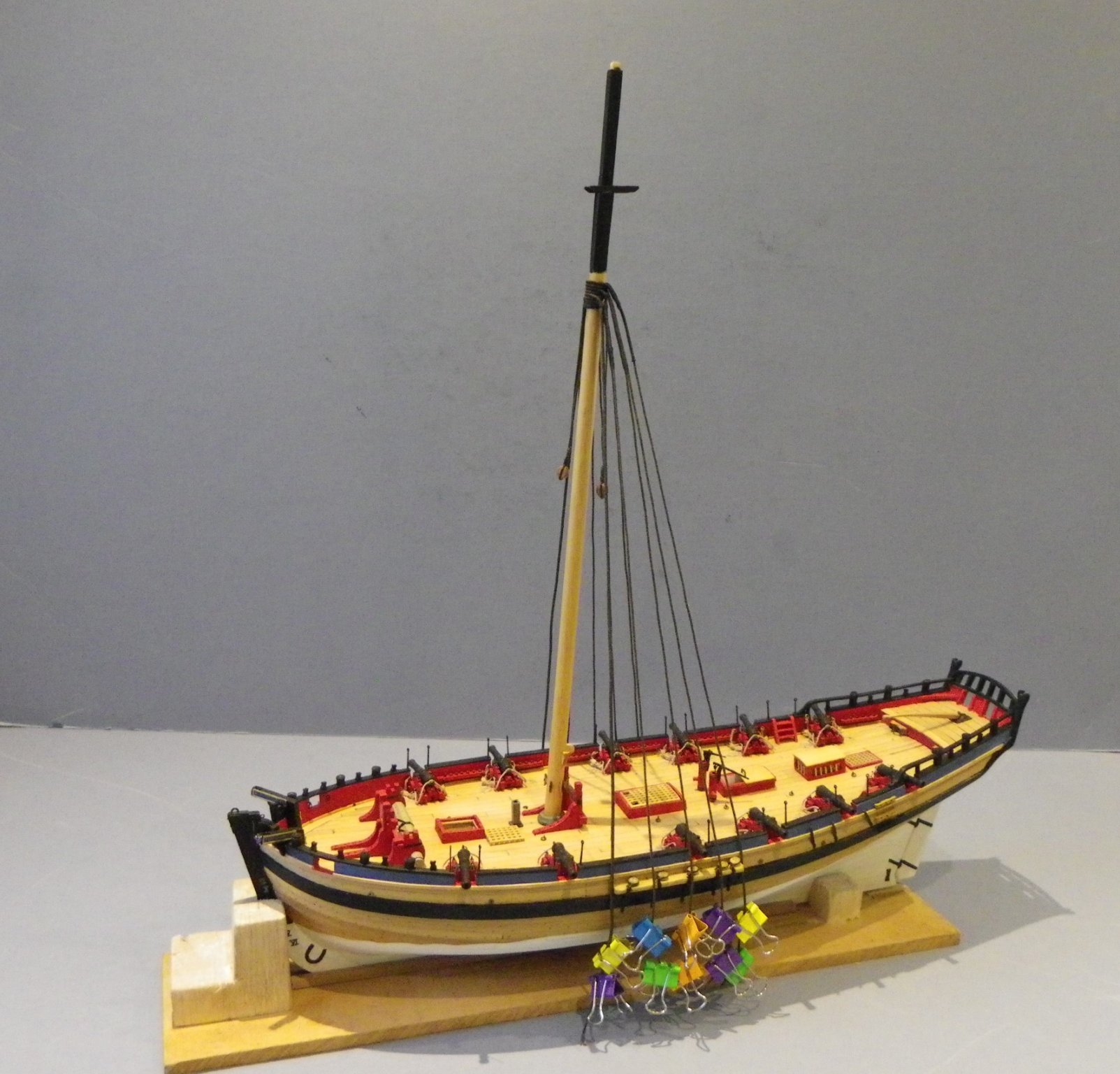
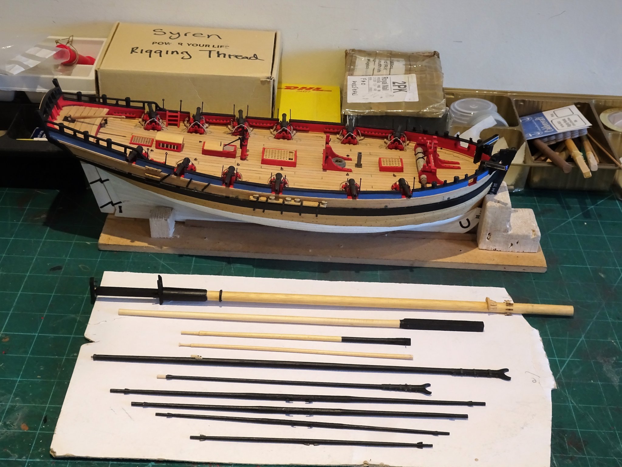
Post 56 Build Part two – Masting and rigging Marking the seven month build stage of this fine little kit from Vanguard Models. 4373 The work bench is cleared of the detritus built-up over the past months in preparation for the second build stage. 4378 Ready to go now with the masting and rigging. B.E. 18/01/2020

- 335 replies
-
- 23
-
-
- alert
- vanguard models
- (and 1 more)
-
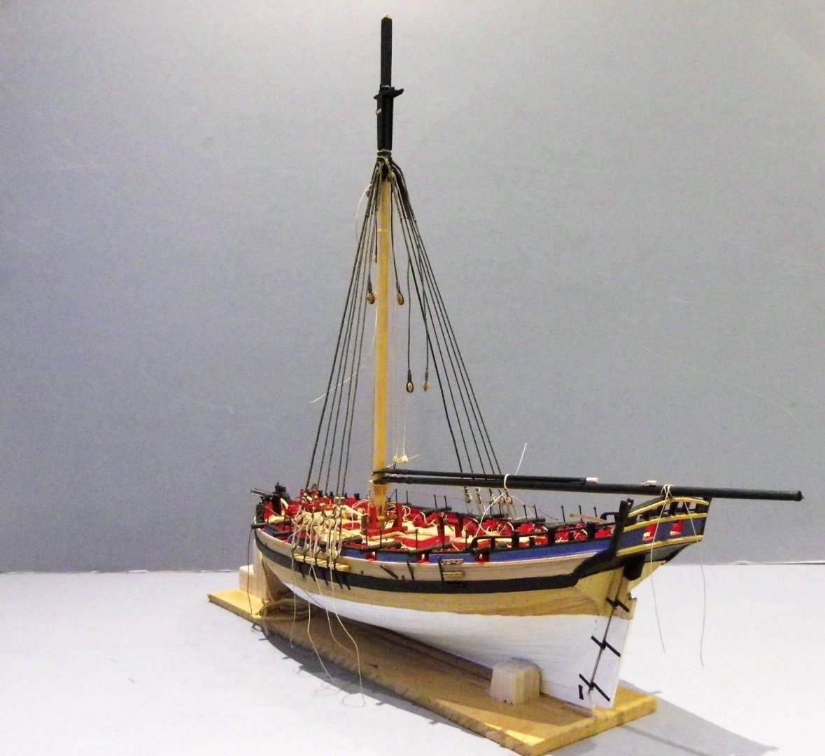
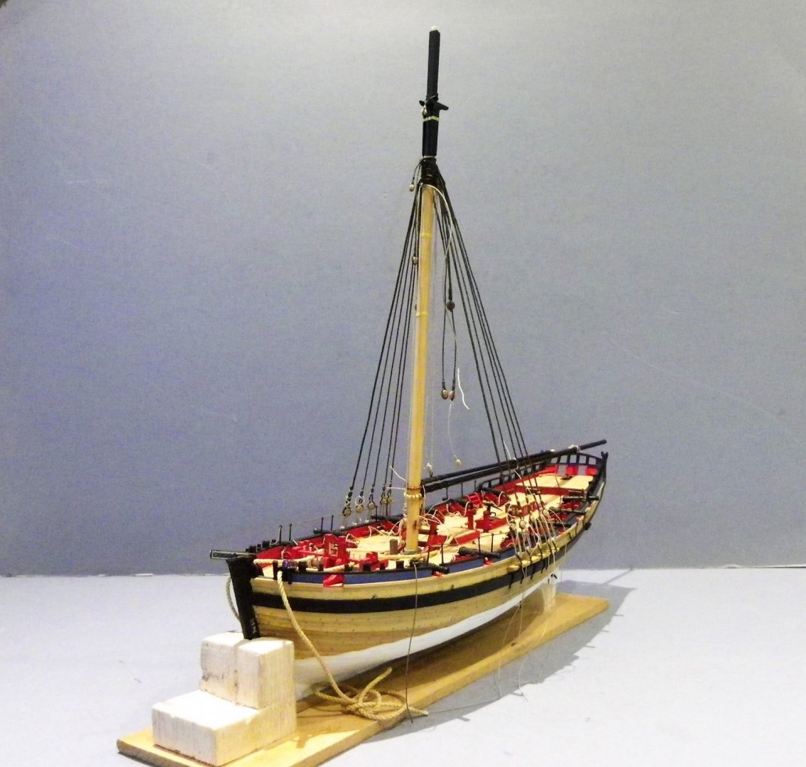
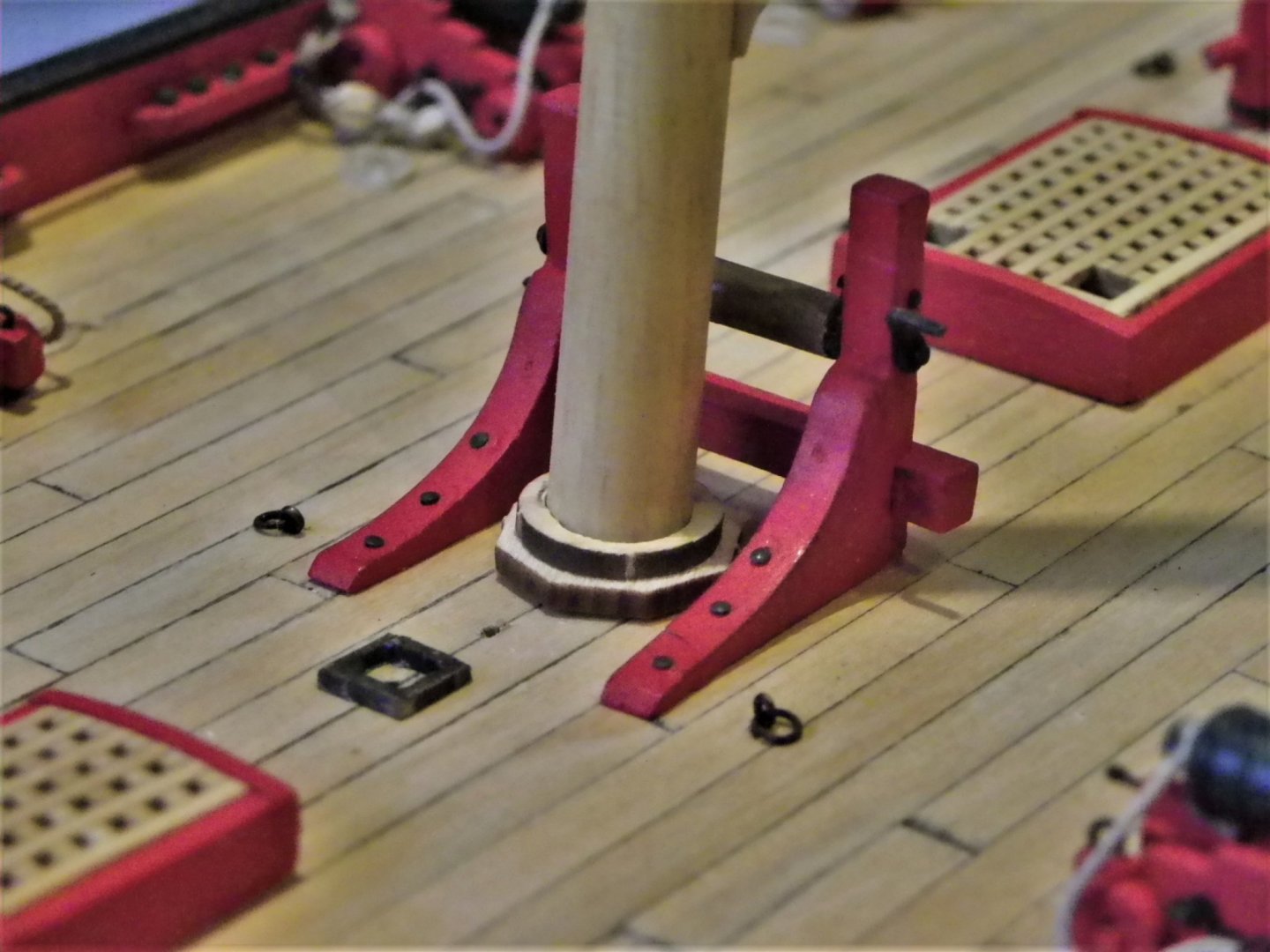
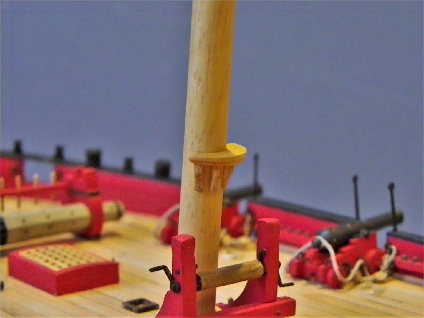
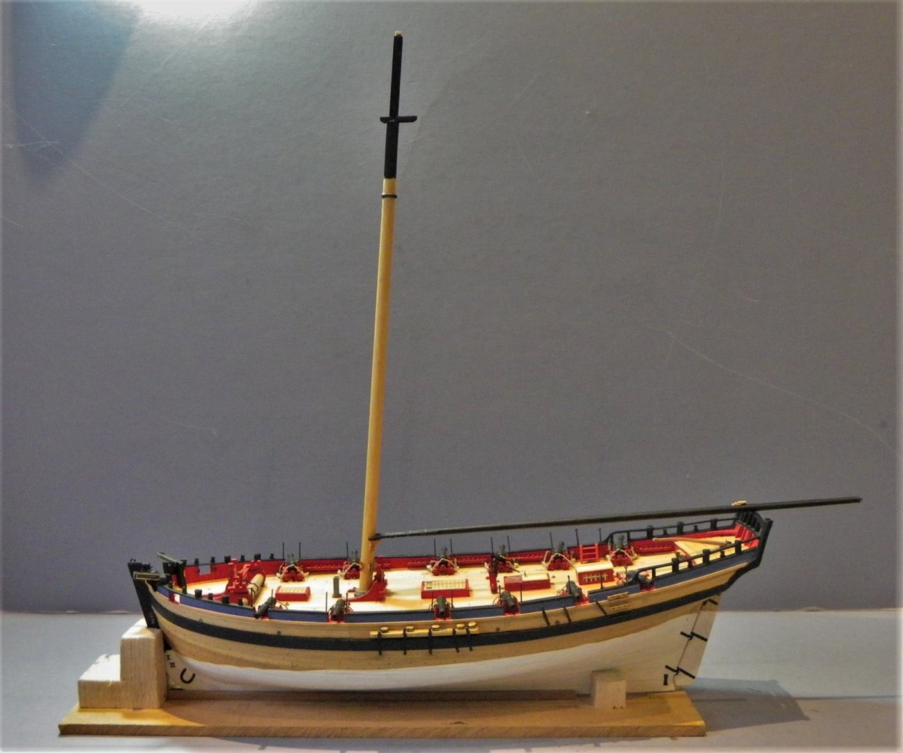
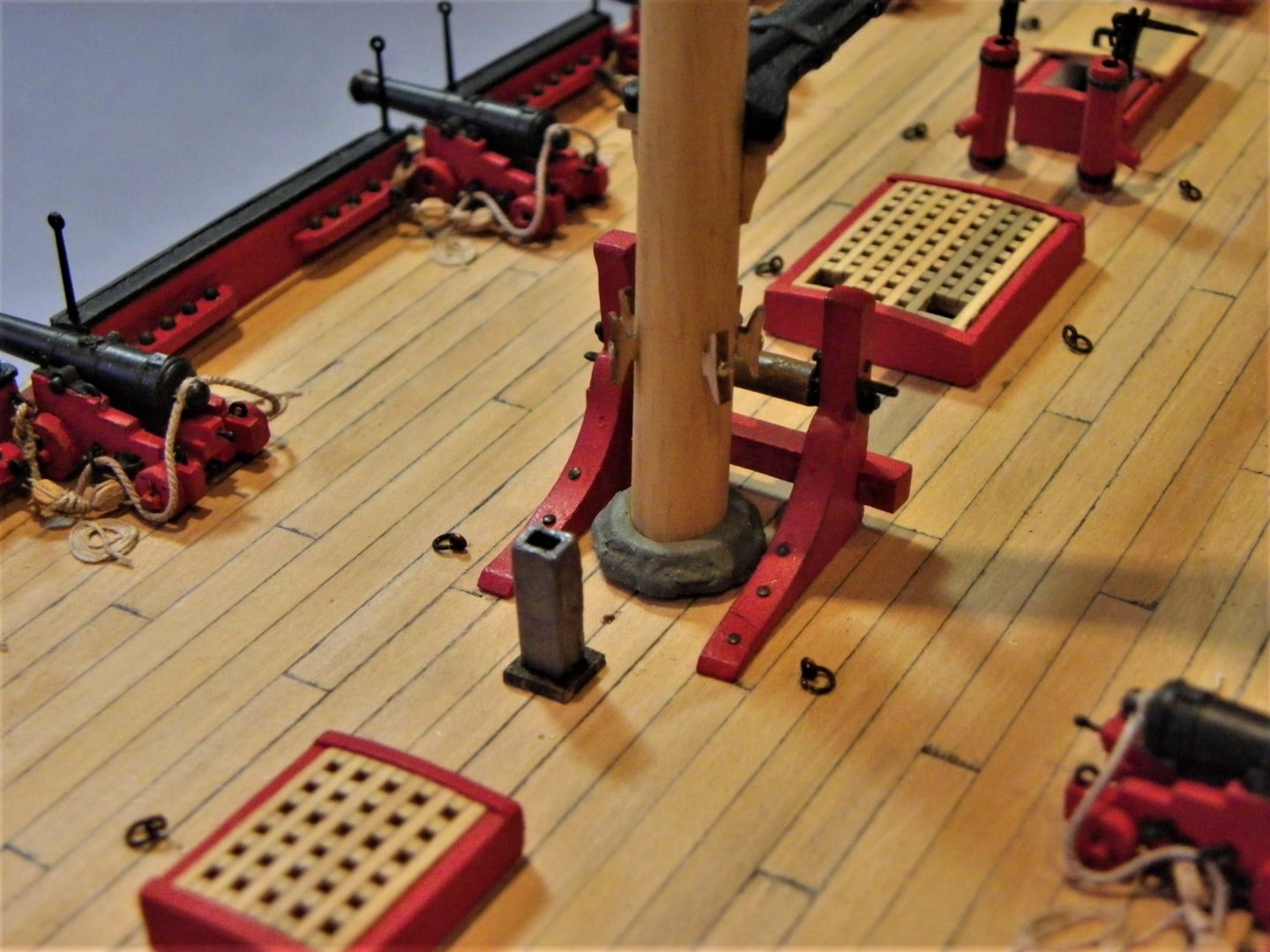
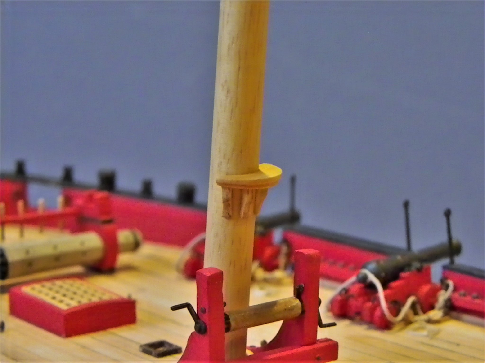
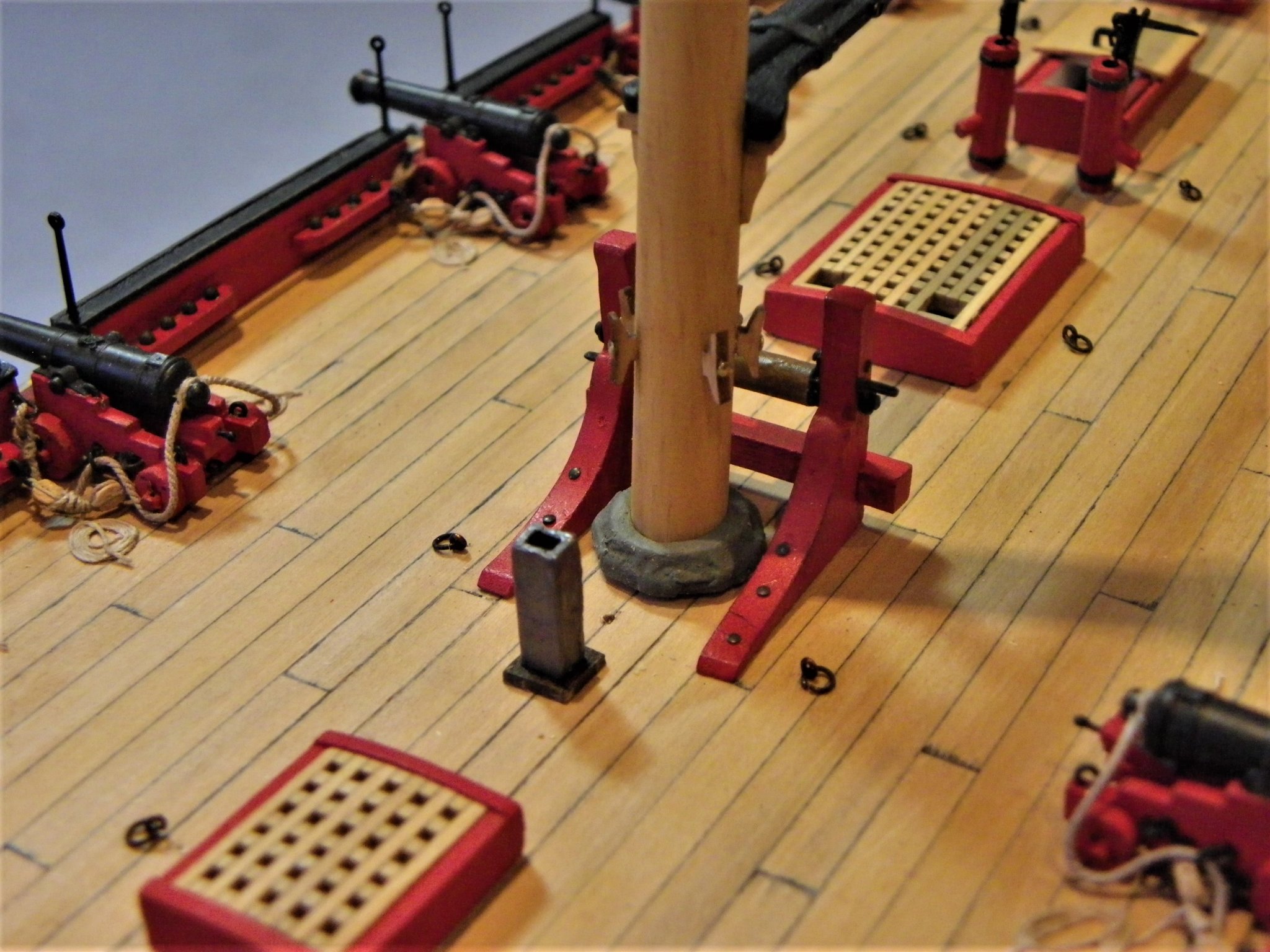
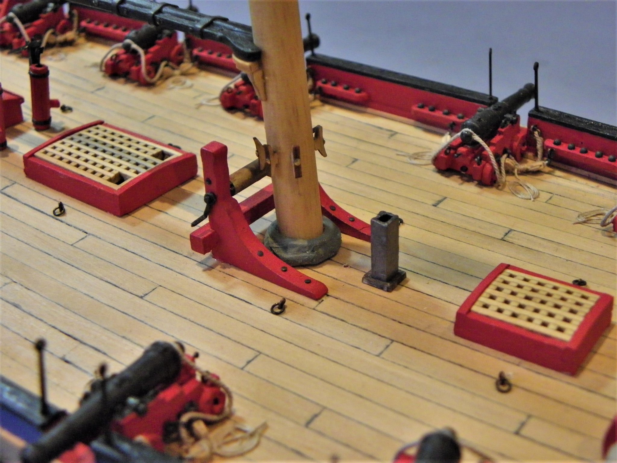
Post 55 Finishing off the mast. There are sheaves to be cut, cleats to be added, and the mast surface to be finished. Below the cheeks are the rigging stops; these are what the shrouds and other tackle sit on. The kit provides (4) etched cleats to perform this function, they are the same type as used on yard arms and look a little light weight to my eye. My concern is are they enough to stop slippage of the shrouds down the mast. The Alert Book shows what is called a rigging stop (iron hoop) to perform this function. It is very difficult to determine what was used from models as all the mast head tackle hides this support from view. 0115(2) I opted for a hoop style rigging stop and fitted this 44mm below the trestletrees which is some 5mm lower than the kit plan. I need to make sure that there is enough space to fit all the rigging between the stop and the cheeks. There are a dozen or more large diameter served lines seized around the masthead at this point. At the base of the mast 7’ above deck (kit dimensions) is the saddle to support the jaws of the boom. 0105 I remade this out of Boxwood to add a profile. I note that the Alert book drawings at 1:64 show the saddle only 5’4” above the deck (25mm) which barely clears the winch bitts. At deck level the kit provides an octagonal ‘mast base’ 0104 I built this up and covered it with microporous tape to represent the mast coat. 0113 The kit also provides an etched spider band placed below the saddle about 4’ above the deck. 0118 I’m not sure about this and I used cleats around the mast in preference. 5mm Boxwood cleats from Syren are spot on for the job. Main Boom I have already modified the jaws of the boom, but I preferred a stop cleat atop the boom for the sheet tackle. 0116(2) Lees suggests that up to 1818 a ferrule and eye were fitted to the end of the boom and a sheave cut in about six inches from the end. 0130(2) I adopted this arrangement rather than the kit set up. Gaff 0124 As with the boom, the jaws have been modified and in the case of the Gaff the inner face is angled somewhat to suit the angle of the Gaff in normal use. T’Gallant Mast 0121(2) Two small detail additions are made to this mast; eyebolts beneath the mast cap, and the top rope sheave at the mast heel. 0109 Apart from the black painted masthead area, wipe-on poly is used to seal and enrich the colour of the birch dowel mast. So, the full masting set is now complete, and the second build part can begin. Once the mast is in place keeping the model dust free becomes more of a problem, so at this point I have ordered the case. For a relatively small hull size the model case dimensions are quite large; Internally 750mm long x 555mm high x 280mm wide. This is not very much smaller than the case for Pegasus but is explained by the lofty rig and long Bowsprit of Alert. B.E. 17/01/2020
.thumb.JPG.9686f59457b459b67e7205e125b29c01.JPG)
.thumb.JPG.ffa2ad09b8d927ad5eac602370b87768.JPG)
.thumb.JPG.13025c32dd5ec6e9edaf1ab715651b3f.JPG)
.thumb.JPG.3e59d7101cfdddc587f35ec70b237e55.JPG)
- 335 replies
-
- 20
-
-
- alert
- vanguard models
- (and 1 more)
-
At model scale I never use commercial black thread, it is far too stark. My approach is to use natural thread and dye it with dark Jacobean oak wood dye. It produces a far better scale effect and over time fades slightly, to even better effect. B.E.

.JPG.2501ddef11982fc21579e33729706bb8.JPG)


.jpg.45e575e884178d517c800076771fc604.jpg)

.JPG.928b4c6db904126964756c9af180eb9d.JPG)

.JPG.0806760bc478c175d8afc104996c2f77.JPG)
.JPG.03804b41df986d824aa35b14a86c0d10.JPG)
.JPG.3a29e9ff2101864ecf17eeafea5663d2.JPG)

.JPG.1ac998f601c95d46348795ebaed15145.JPG)
.JPG.9faf5f00249c178615f64179ac774f0d.JPG)
.JPG.1c9a99180ec58d4d9e553becafe89e2e.JPG)


.JPG.ad4caaf0d443f17a52e0c0482a4770ec.JPG)
.JPG.c19e9420e6887cfb170d1888640af868.JPG)
.JPG.edac668257e7e7ae3fc0a7f785be4381.JPG)

.JPG.5db5d964c91db6645de48c777b09984e.JPG)