
.JPG.ca33079f5815b861e67b9c2cccd37982.JPG)

Blue Ensign
-
Posts
4,569 -
Joined
-
Last visited
Content Type
Profiles
Forums
Gallery
Events
Everything posted by Blue Ensign
-
 Thanks Rusty, I sometimes wonder if I give too much information in the log, but I use the text as an aide memoire to myself, I still refer to my previous logs as I often can't remember how I did things.🙄 If others find this stuff of use all the better.😃 Cheers, B.E.
- 335 replies
-
- 5
-

-
- alert
- vanguard models
- (and 1 more)
-
Looks good to my eye Vane, well done. 👍 B.E.
-
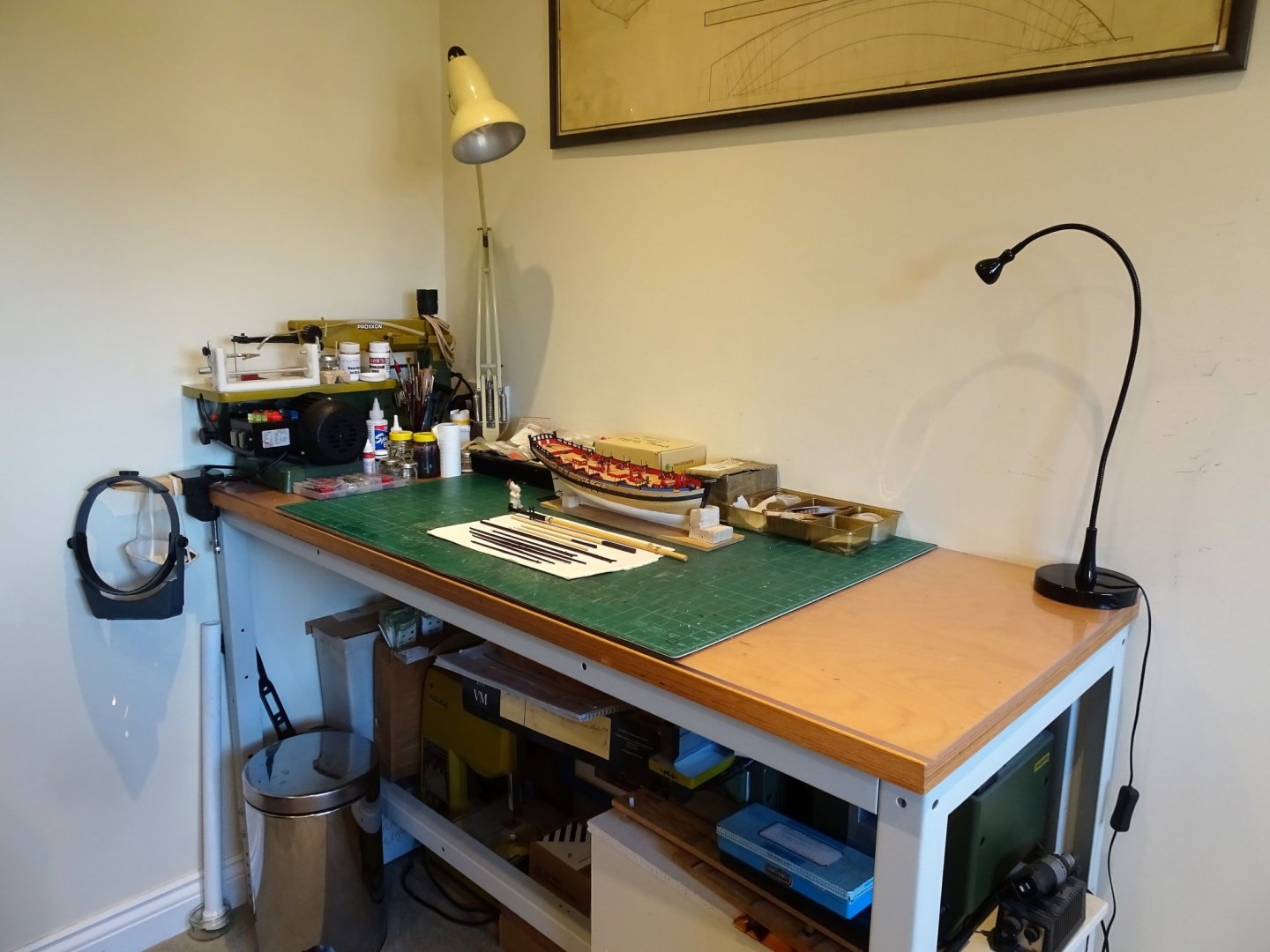
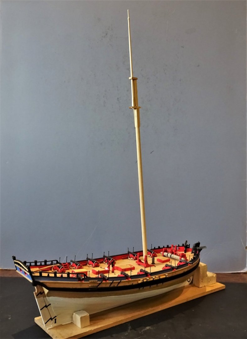
Post 56 Build Part two – Masting and rigging Marking the seven month build stage of this fine little kit from Vanguard Models. 4373 The work bench is cleared of the detritus built-up over the past months in preparation for the second build stage. 4378 Ready to go now with the masting and rigging. B.E. 18/01/2020

- 335 replies
-
- 23
-
-
- alert
- vanguard models
- (and 1 more)
-
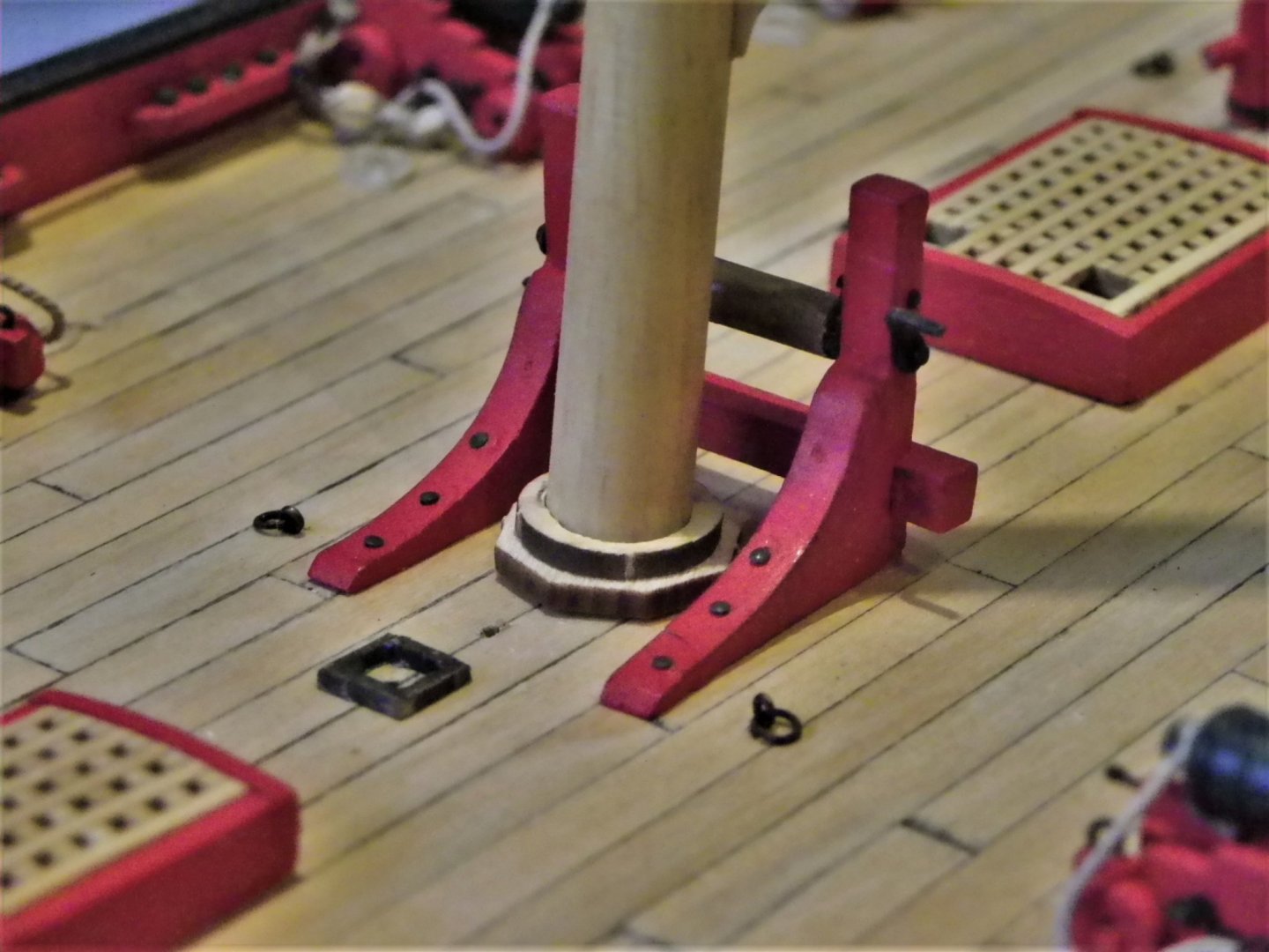
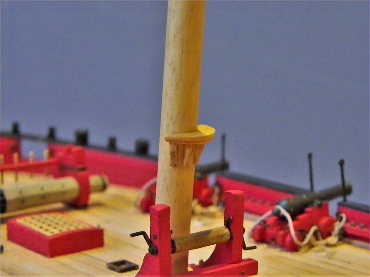
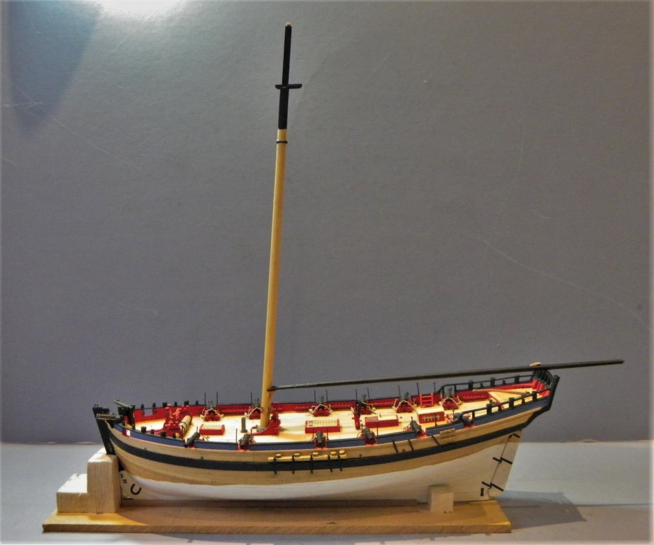
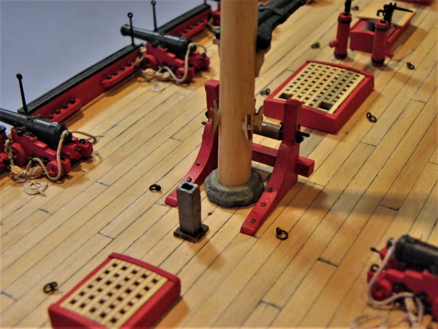
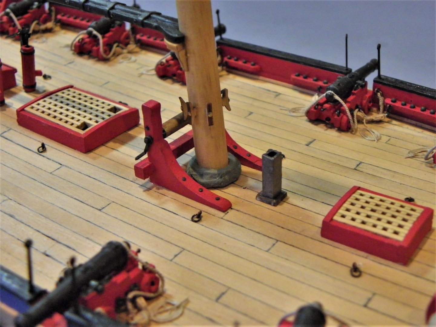
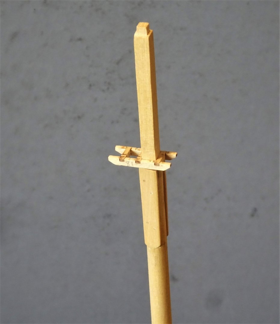
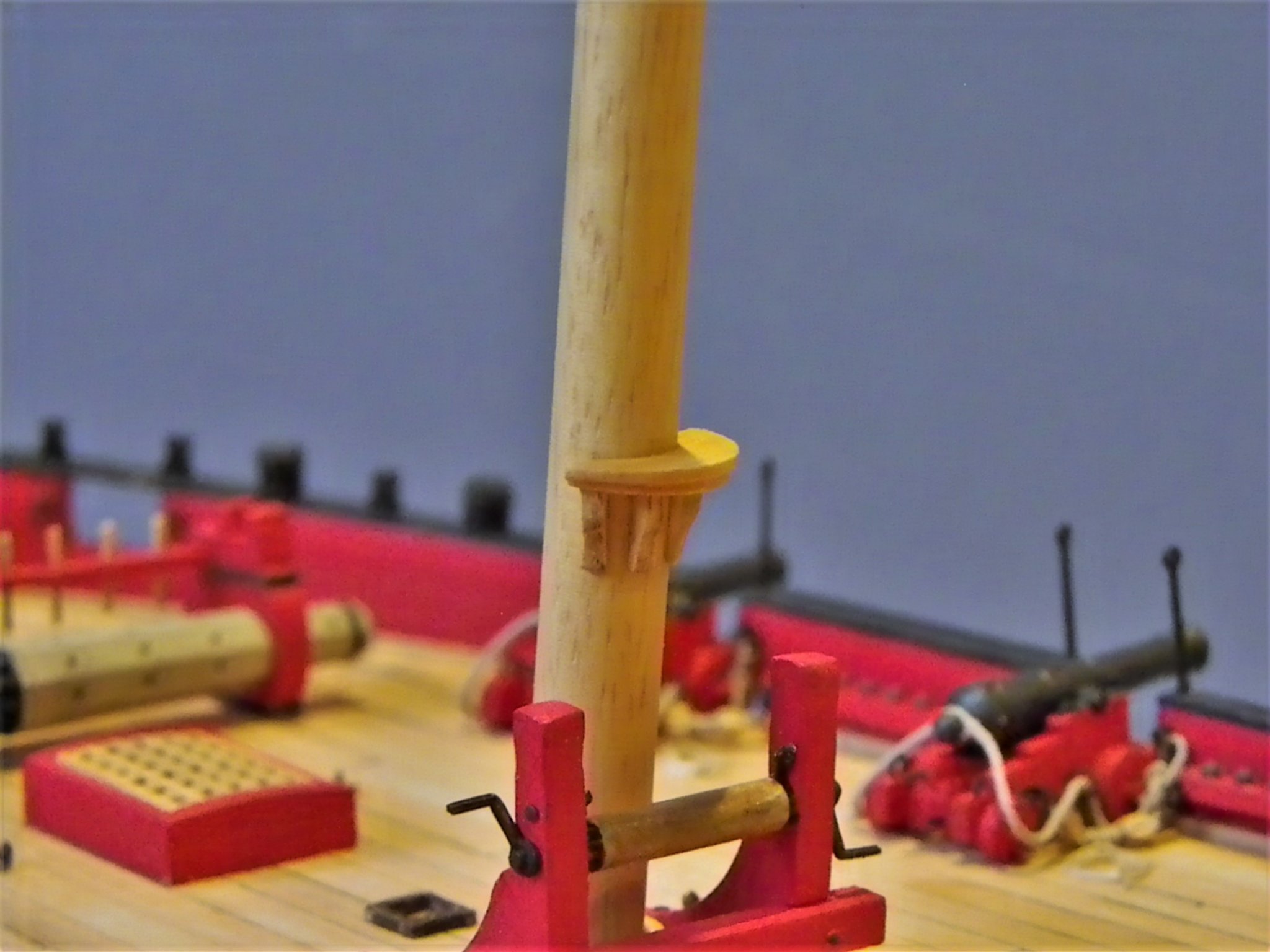
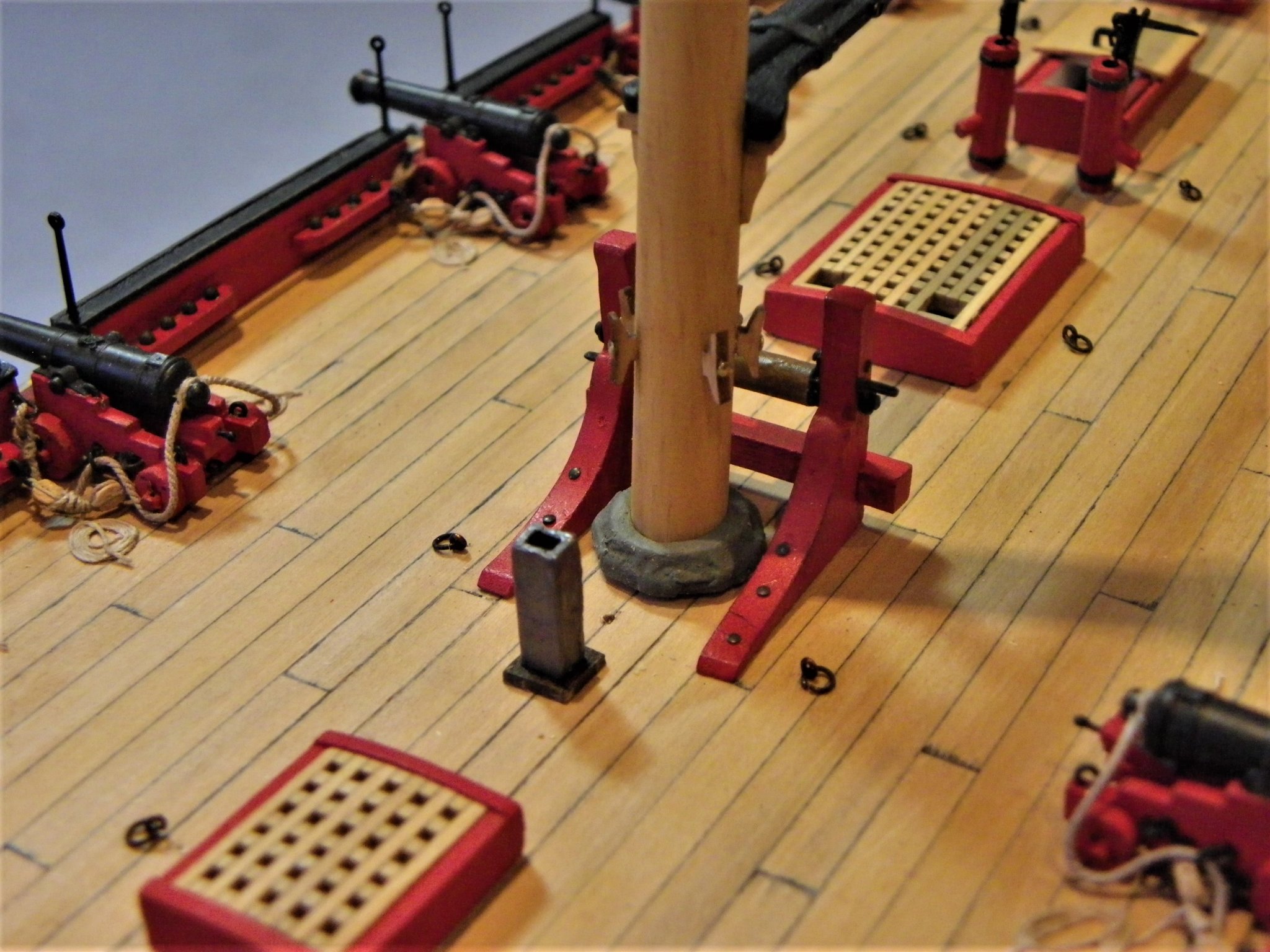
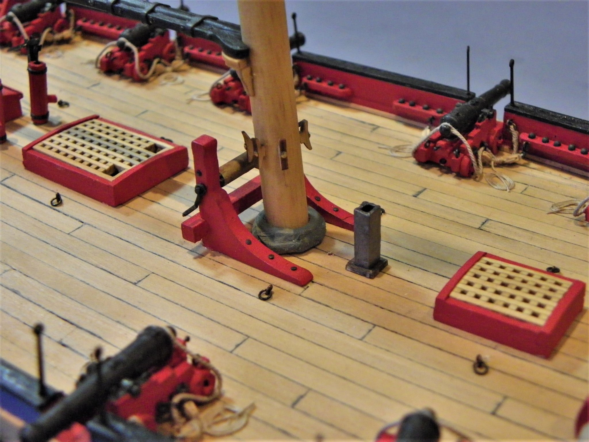
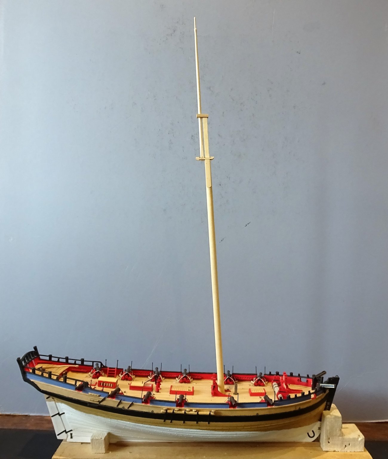
Post 55 Finishing off the mast. There are sheaves to be cut, cleats to be added, and the mast surface to be finished. Below the cheeks are the rigging stops; these are what the shrouds and other tackle sit on. The kit provides (4) etched cleats to perform this function, they are the same type as used on yard arms and look a little light weight to my eye. My concern is are they enough to stop slippage of the shrouds down the mast. The Alert Book shows what is called a rigging stop (iron hoop) to perform this function. It is very difficult to determine what was used from models as all the mast head tackle hides this support from view. 0115(2) I opted for a hoop style rigging stop and fitted this 44mm below the trestletrees which is some 5mm lower than the kit plan. I need to make sure that there is enough space to fit all the rigging between the stop and the cheeks. There are a dozen or more large diameter served lines seized around the masthead at this point. At the base of the mast 7’ above deck (kit dimensions) is the saddle to support the jaws of the boom. 0105 I remade this out of Boxwood to add a profile. I note that the Alert book drawings at 1:64 show the saddle only 5’4” above the deck (25mm) which barely clears the winch bitts. At deck level the kit provides an octagonal ‘mast base’ 0104 I built this up and covered it with microporous tape to represent the mast coat. 0113 The kit also provides an etched spider band placed below the saddle about 4’ above the deck. 0118 I’m not sure about this and I used cleats around the mast in preference. 5mm Boxwood cleats from Syren are spot on for the job. Main Boom I have already modified the jaws of the boom, but I preferred a stop cleat atop the boom for the sheet tackle. 0116(2) Lees suggests that up to 1818 a ferrule and eye were fitted to the end of the boom and a sheave cut in about six inches from the end. 0130(2) I adopted this arrangement rather than the kit set up. Gaff 0124 As with the boom, the jaws have been modified and in the case of the Gaff the inner face is angled somewhat to suit the angle of the Gaff in normal use. T’Gallant Mast 0121(2) Two small detail additions are made to this mast; eyebolts beneath the mast cap, and the top rope sheave at the mast heel. 0109 Apart from the black painted masthead area, wipe-on poly is used to seal and enrich the colour of the birch dowel mast. So, the full masting set is now complete, and the second build part can begin. Once the mast is in place keeping the model dust free becomes more of a problem, so at this point I have ordered the case. For a relatively small hull size the model case dimensions are quite large; Internally 750mm long x 555mm high x 280mm wide. This is not very much smaller than the case for Pegasus but is explained by the lofty rig and long Bowsprit of Alert. B.E. 17/01/2020
.thumb.JPG.9686f59457b459b67e7205e125b29c01.JPG)
.thumb.JPG.ffa2ad09b8d927ad5eac602370b87768.JPG)
.thumb.JPG.13025c32dd5ec6e9edaf1ab715651b3f.JPG)
.thumb.JPG.3e59d7101cfdddc587f35ec70b237e55.JPG)
- 335 replies
-
- 20
-
-
- alert
- vanguard models
- (and 1 more)
-
At model scale I never use commercial black thread, it is far too stark. My approach is to use natural thread and dye it with dark Jacobean oak wood dye. It produces a far better scale effect and over time fades slightly, to even better effect. B.E.
-
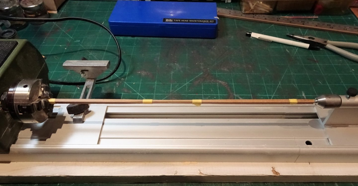
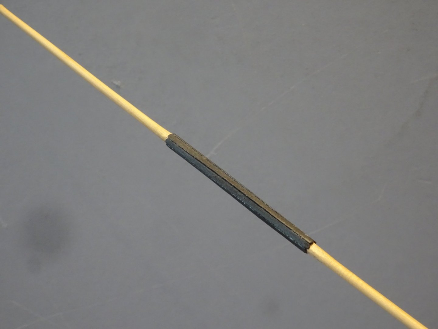
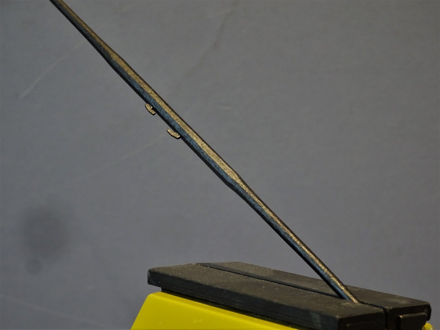
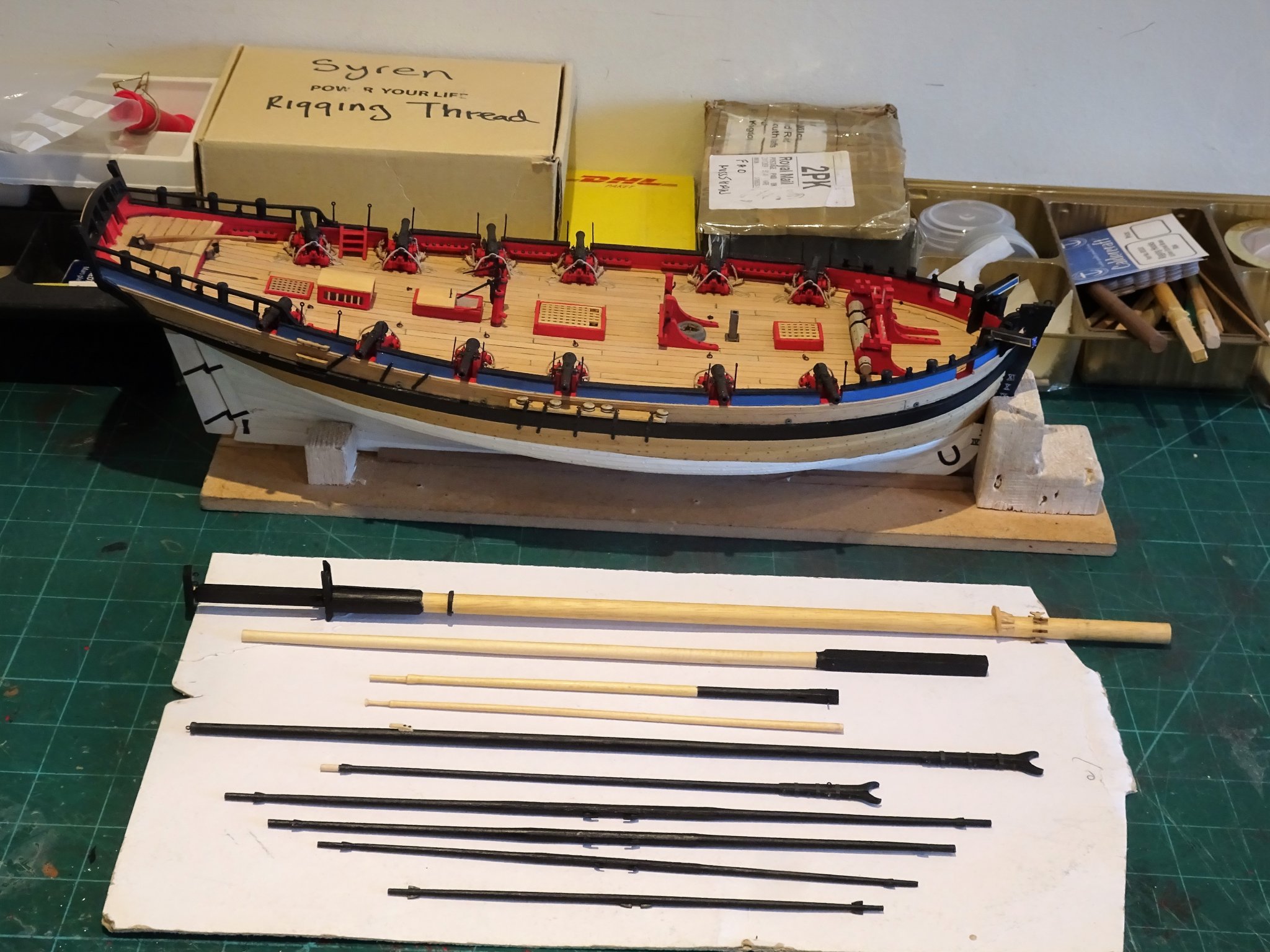
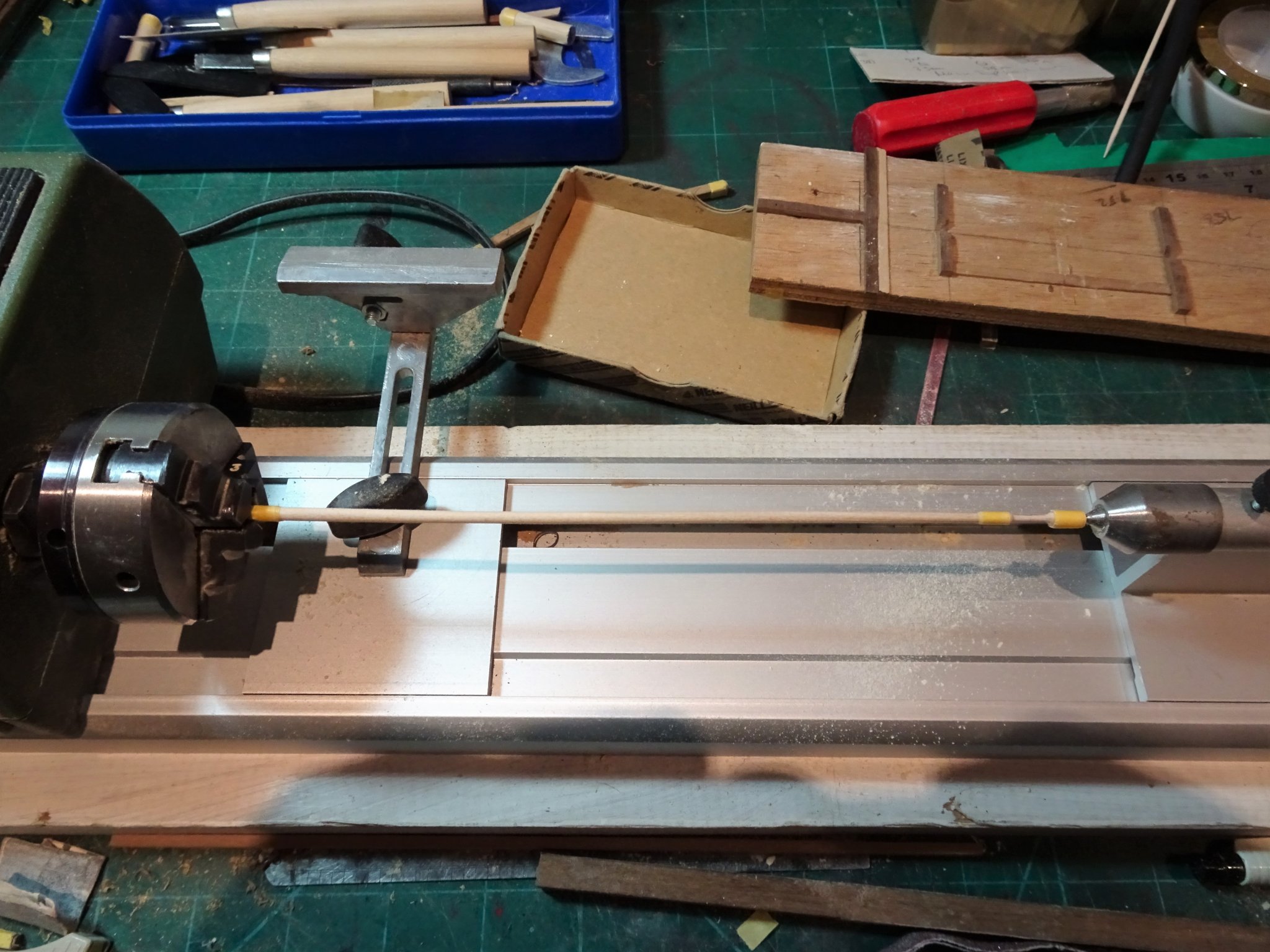
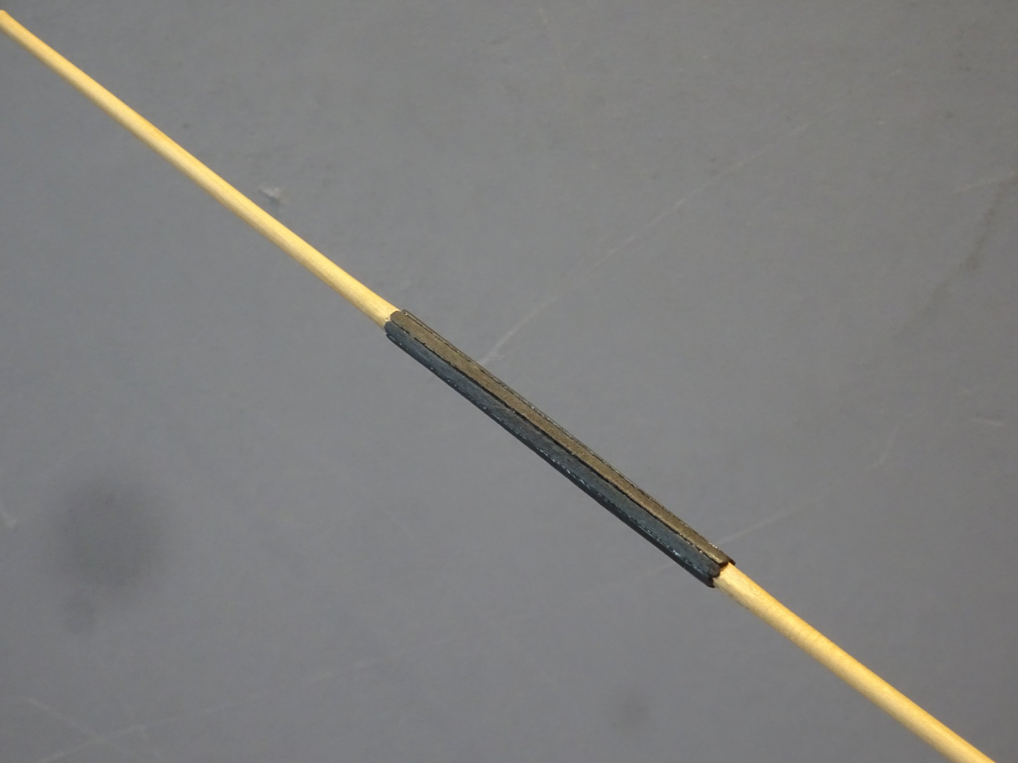
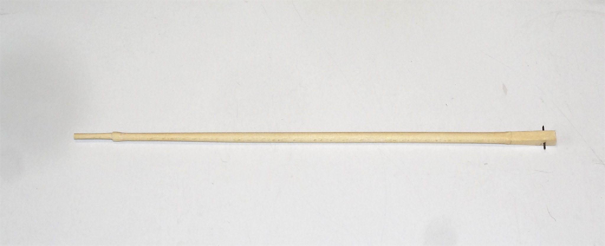
Post 54 Yards There are four yards to be made. T’gallant Yard, Topsail Yard, Square-sail Yard, and Spread-sail Yard. The kit follows the dimensions of the drawings in the Alert Book. There is a problem in correlating sizes to other sources as not all described yards are included. The Adm Plan only includes the Topsail Yard (4’ shorter) and the Square-sail Yard (2’ longer) I have decided to follow the yard dimensions as per the kit/Alert Book. I start with the Spread-sail yard, the largest spar. Altho’ the kit instructions don’t cover the detail; the centre sections of most yards were octagonal in shape and for this reason I am making the yard from square stock. 4325 To form the octagon the yard is put in a ‘V’ jig and thereafter the arms are rounded on the lathe, tapering down to 2mm ø. The Square-sail and Topsail yards are made in the same manner, but the T’Gallant is made simply from dowel as there is no octagonal section. Not indicated in the kit but Alert carried a Mizen mast. This slots into iron brackets attached to the face of the stern platform. 4339 Simple enough to create one. 0095(2) Made from 3mm ø dowel with a length of 170mm. 0086(2) 0091(3) This won’t be displayed erected on the model but stored on the deck. The yard furniture consists of Sling cleats and yard arm cleats, provided in brass etch form in the kit. 0101(2) I initially had mixed feelings about the kit pieces; on one hand they are a neat and effective way of adding these items but look a little thin to my eye and will need painting. On the other hand, making these items is a fiddly business, and only a wood like Box or perhaps Pear is suitable, and they are very tiny. 4362(3) When I tried the etched items, I thought they looked ok, so the kit items it is. I chemically blackened them before use. Had I intended to varnish rather than paint the yards, then the wood option would have been necessary. One other item to consider is the addition of thin battens covering the octagonal sections. To batten or not to batten, that is the question. Goodwin in the Alert book writes that in ‘all probability’ the Square sail yard was made from two pieces and had battens; but was ‘not altogether certain’ that the Spread-sail yard was similarly made but thought it likely. Lees indicates that the battening of yards which began in 1773 related to two-piece yards on larger ships, and that the practice was normal on most ships after 1805 except for small vessels. David Antscherl also omitted them from the yards in his rigging book on the Sixth rate Sloop. (Vol 1V) I didn’t add battens to my Pegasus build. Apart from some historical doubt and the absence of this feature on contemporary cutter models I have some reservations about adding these simply from an aesthetic viewpoint. At model level there is a tendency for them to make the yard centres look too bulky to my eye, even tho’ at 1:64 scale they would be a mere 0.3mm thick. 4360(2) Even so out of curiosity I mocked up an example starting with some 0.5mm strip. 4359 I prefer the unbattened look and am happy to omit them on this build. 4361 Completed Spread-sail Yard. 4363(3) The Yard set for Alert. B.E. 14/01/2020

.thumb.JPG.d5286849d408946f7ee6cbeae68ebf82.JPG)
.thumb.JPG.c03935fc7b6c858b227f007baa646c63.JPG)
.thumb.JPG.3cd83ed9f44d69dc27118423e6e7b24a.JPG)
.thumb.JPG.b4889c14f0452530b42060166cae01bd.JPG)
.thumb.JPG.bc4a48d1d3b3391fd590e92ee023d948.JPG)
.thumb.JPG.a08bce5a7e44ade5eab2898fbac45df8.JPG)
.thumb.JPG.084a2ced21c5064471f91d36de66c08f.JPG)
- 335 replies
-
- 17
-
-
- alert
- vanguard models
- (and 1 more)
-
Coming along beautifully Steve, nice progress.👍 B.E.
-
Hi bitter, You have made a very nice job of completing the hull, but the run of planking up to the bow is not as you say historically correct in relation to Pegasus in particular, and British ships of the era in general. This is not going to really detract from the beauty of your hull as a model, but if it bothers you, coppering would cover most of the lack of tapering of the bow planking. Regards, B.E.
-
Thank you Vane. I used Boxwood strip for both Deck and hull planking. Above the wale I used the kit provided 1mm thick Boxwood Strip, (which is actually supplied for the decking), and below the wale some thinner stuff, 0.7mm thick. I also used the thinner Boxwood strip for the decking. Cheers, B.E.
-
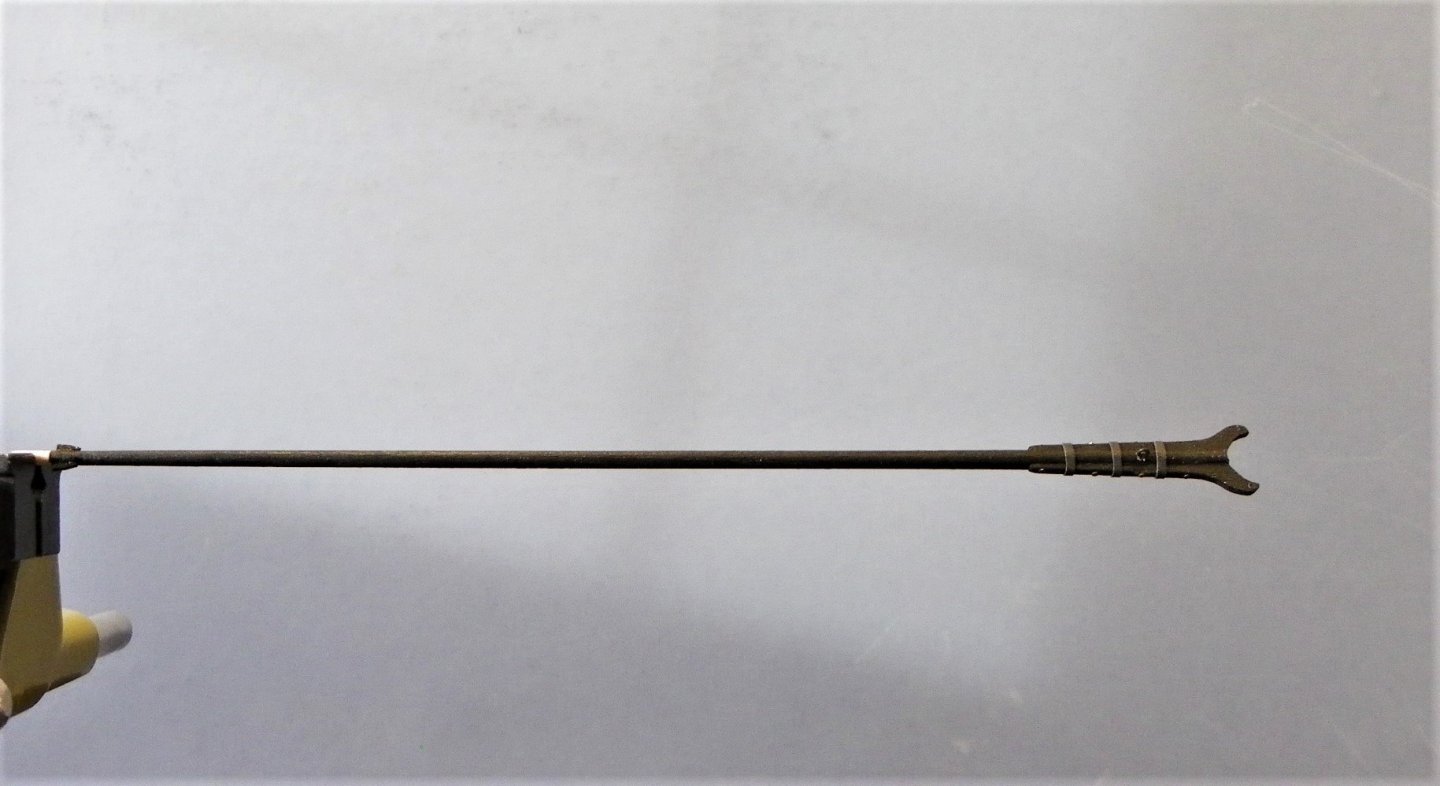
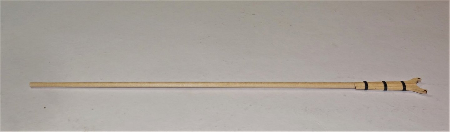
Post 53 Booms and Gaffs Another case of confusing terminology here. The kit lists a Main Boom (283mm) and a Driver Boom(181mm) I think the Gaff has been misnamed as a Driver Boom in the kit instructions, altho’ the overall dimensions are in keeping with a Gaff. The Alert Book Drawings have a (Main)Boom (273.75mm) and a Gaff, (171mm) but also show a Storm Gaff (79.5mm) and a Driver Boom (184.5mm). Sizes scaled up from 1:96 drawings. The Admiralty plan lists: A Boom 58’10” (280mm) 12⅝” ø (5mm) A Gaff 40’ 0” (190.5mm) 9” ø (3.6mm) A Storm Gaff 17’ 0” (81mm) 93/8” ø (3.72mm) A Driver Boom 27’ 0” (128.5mm) 6¾” ø (2.7mm) The Alert Book links the Driver Boom to the Storm Gaff, presumably for carrying reduced sail. The Main Boom is linked to the Gaff. Steel Main Boom 66’ (14¼”ø) (314mm) Gaff 49’ 6” (10¼”ø) (235.7mm) Driver Boom 42’ (8”ø) (200mm) Storm Gaff 21’ ( 8¼”ø) (100mm) As can be seen there are variations, some of them greater than others, so you pays your money and takes your choice. For my build I am going with the kit despite the gaff about the gaff. Booms were not evenly tapered, and ship and cutter booms differed in their proportions. According to Steel:- For Cutters. The maximum dimension is towards the outer end at the point of the sheet, just inboard of the stern. Taper is then made both inboard and outboard to given proportions. The inboard section is quartered as follows; Max scale diameter 5mm 1st Qtr 2nd Qtr 3rd Qtr 4th Qtr 40/41 11/12 7/8 2/3 4.87mm 4.58 4.37mm 3.3mm Outboard section Mid Point End 11/12 ¾ 4.58mm 3.75mm I made a boom to these proportions and it looks good to my eye. 4318 This shape is not reflected in the kit where the maximum diameter is at the inboard end, tapering to 3mm at the outboard end. The Jaws The kit provides a simplified all-in-one version that simply slots over the end of the boom. In practise the jaw and tongue were made up of separate sides, port and starboard, fayed and bolted to the chamfered boom end. 4317(2) The ‘iron’ bands are only there temporarily at present. I don’t really like kit boom jaws they always look unconvincing. I did use the kit version, but I split it and fined it down to suit my eye. One of the worst examples I have seen of pre-formed boom jaws, is a lumpy, clumpy, blocky, example provided in the Pickle kit, but it is easily remedied. The Gaff 4320(2) This was made as per the Boom, but the maximum dimension is 19mm from the inboard end. Maximum scale diameter 3mm. 1st Qtr 2nd Qtr 3rd Qtr 4th Qtr 40/41 11/12 4/5 ¾ There is still the finishing to do but that can wait until the yards are made. My aim is to get the sawdusty element out of the way and clean up before I get onto the finishing. B.E. 10/01/2020
.thumb.JPG.ff12791fec01e22f7403d703686ab39f.JPG)
.thumb.JPG.e5773e0036cf79f83bd26cf57f4918a7.JPG)
- 335 replies
-
- 13
-
-
- alert
- vanguard models
- (and 1 more)
-
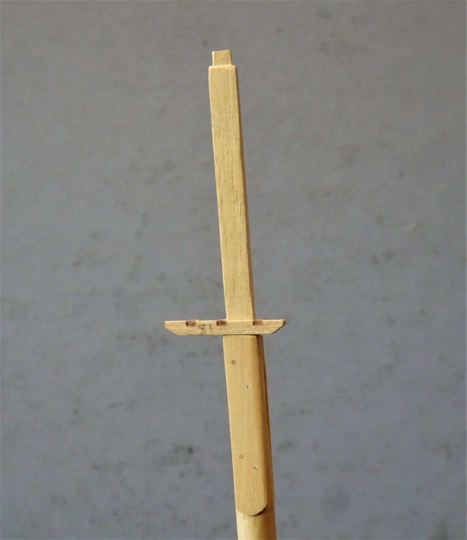
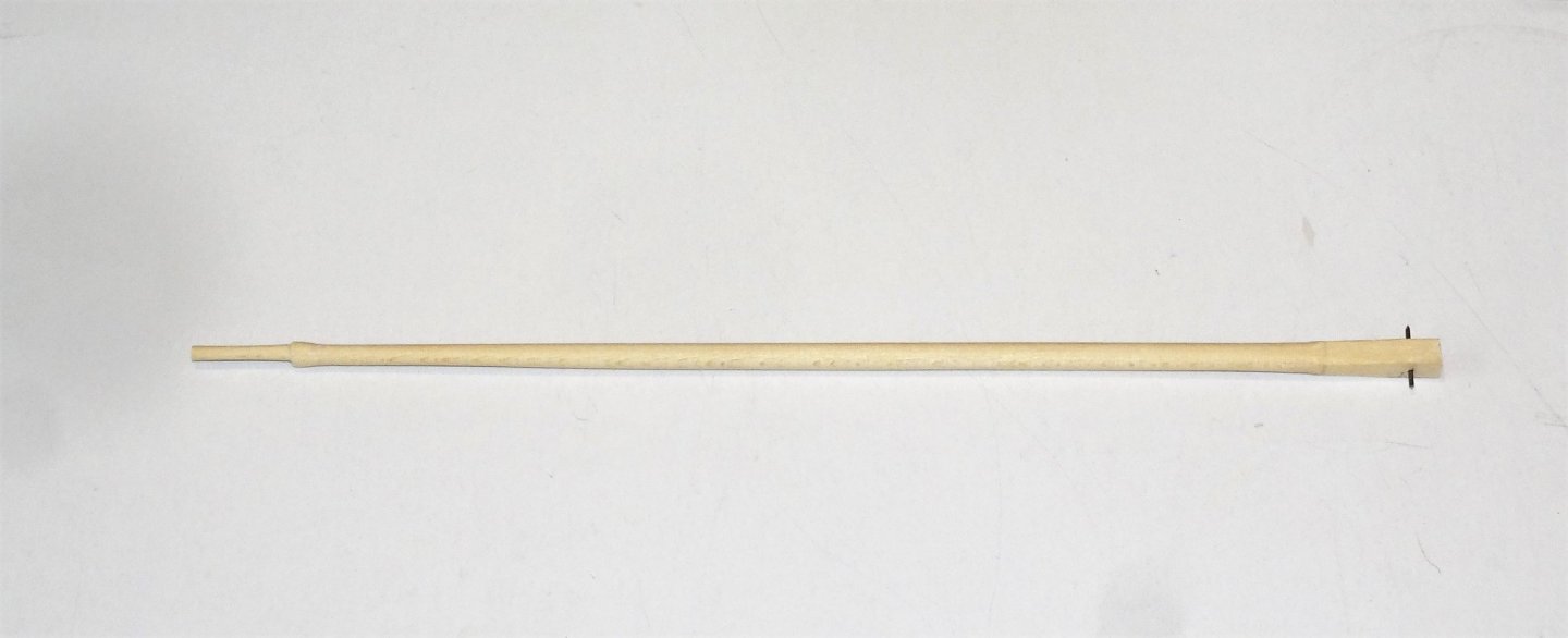
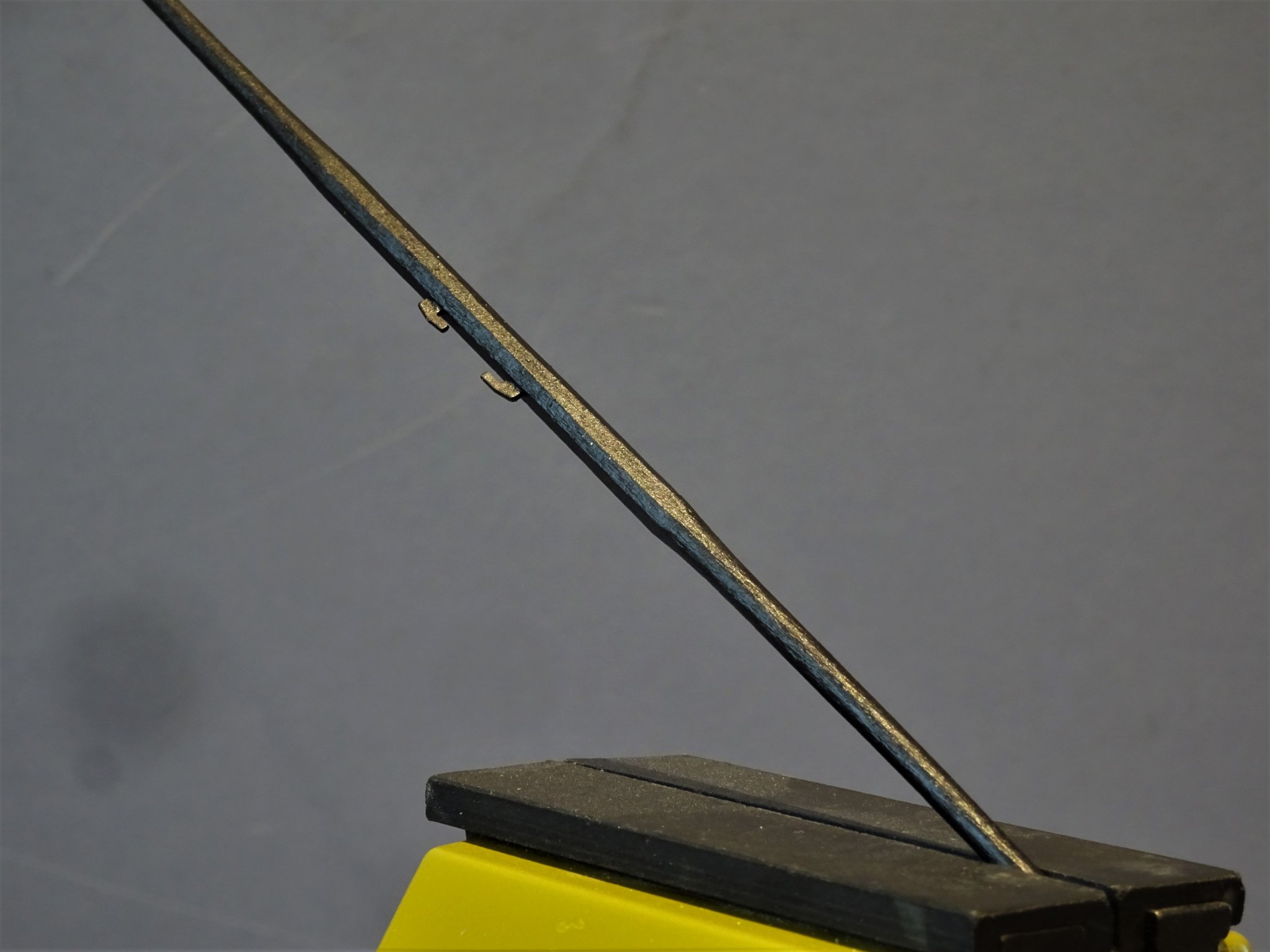
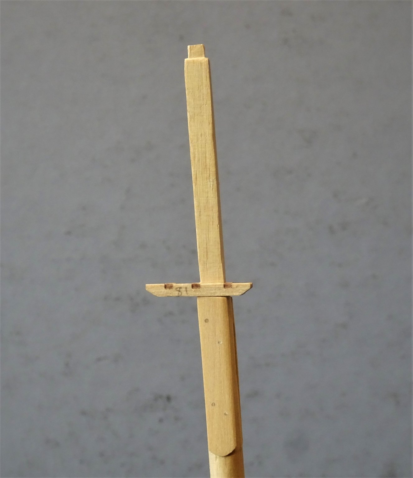
Post 52 Mast and Yards In preparation for mast and yard making, my standard approach is to firstly compare the given dimensions across several sources. I compared the scale lengths as per a) the kit. b) Steel. c) The Alert Book. d) Admiralty Plan. The Bowsprit I have already made to the kit dimensions, which are very close to the Admiralty plan notation. The main/topmast is the first job. (In Cutters the main/topmast are combined to make one lower mast. Kit Steel Alert book Adm Plan Length 367mm 419.1 423.9mm 373.8mm Diameter 8mm 8.7mm 8.7mm 8.0mm With a diameter of 20” (8mm scale) *The quarters work out as follows: Partners 1st Qtr 2nd Qtr 3rd Qtr 20” 19¾” 18¾” 17⅟8” Scale 1:64 8mm 7.83mm 7.44mm 6.8mm *Taken from Steel. The kit taper from 8mm to 7mm is close enough, and the dimensions given in the kit instructions matches those of the Alert Book. I like to mark the quarters on the dowel to get as far as possible an even taper during sanding. 4236 I am making the mast from some Ramin dowel, so this will entail either adding the square section above the cheeks with some square stock or taking the riskier route of squaring off the top end of the mast. 4286 I squared off the top section by hand and eye using a fine chisel, content in the knowledge that I could always cut it off If I didn’t like it. Where the cheeks fit, the mast needs to be flattened off and some more fine chiselling is required to set the cheeks into the mast sides. 4285 I somehow lost the kit provided cheeks, but they are easily replaced, cut from Boxwood sheet. Treenails were added to secure the cheeks. Note: there is an orientation to the cheeks, the top is angled upwards aft. This is to compensate for the rake of the mast when fitted and will bring the trestletrees level. With the cheeks in place, the Trestletrees can be test fitted, these follow the line of the cheeks. I used the kit provided laser cut versions which were accurately cut and robust for what is usually a fragile kit item. T’gallant Mast All the references agree to the scale length of 170mm (35’6”) A shorter Storm T’gallant mast of 25’ scaling to 119mm could be used if height is an issue on the model. The kit indicates use of 4mm dowel for the T’gallant mast, but I think there should be a square heel on the mast to fit into the trestletree. 4288 I made the mast from 4mm square stuff and rounded the mast on the lathe. The incorporated Pole head is very narrow (1.5mm ø). 2mm was the smallest diameter I risked on the lathe lest the part snap, and the pole head was finished by hand. The final test is does it all fit together with the Mast Cap. Yes it does.😃 A minor point for the detail obsessed, the hole in the mast-cap to fit the tenon on the lower masthead should really be square not round, as should the Masthead tenon. 4294 I replaced the kit part with a Boxwood version. 4295 4293 4292 Still stuff to do on the masts, sheaves to cut, cleats to add, and finish to be decided. B.E. 08/01/2020
.thumb.jpg.11b587800ad2769bd519585466aaff79.jpg)

- 335 replies
-
- 23
-
-
- alert
- vanguard models
- (and 1 more)
-
We’re all looking at these things removed some 250 years from the time, and your insights and input are always welcome Dirk. Thankyou, B.E.
- 335 replies
-
- 2
-
-
- alert
- vanguard models
- (and 1 more)
-
My understanding is that the Spread-yard was there purely to attach the clews of the Topsail and as such would have had a truss arrangement to secure the yard to the mast. I can't see how a horse would have been of regular benefit, as the Topsail was the sail most likely set . The Square-sail yard ran up and down on the horse to above the Spread-yard, and when used presumably had the sail attached at deck level, as far as I can see there were no footropes on the Square-sail yard. ps. William Falconer's dictionary published in 1780, also describes use of the Horse. HORSE is also a thick rope, extended in a perpendicular direction near the fore or after-side of a mast, for the purpose of hoisting or extending some sail thereon. When it is fixed before a mast, it is calculated for the use of a sail called the square-sail, whose yard being attached to the horse, by means of a traveller, or bull's-eye, which slides up and down occasionally, is retained in a steady position, either when the sail is set, or whilst it is hoisting or lowering. When the horse is placed abaft or behind a mast, it is intended for the try-sail of a snow, and is accordingly very rarely fixed in this position, except in those sloops of war which occasionally assume the form of snows, in order to deceive the enemy. One may presume that Falconer was writing before 1780 which puts his description as being extant at the time of the Alert 1777. B.E.
-
No worry Dirk, it took me ages to get my head around the set up. It doesn't help that different terms are used for the same yard..🙄 B.E.
-
I would have to disagree Dirk, I rather think that the yard and horse were dispensed with in the later rigs. I think Alert sits right in the period where this square-sail arrangement would apply. The Square-sail yard is listed on the Original plans for Alert, and Steel includes the Horse in the rigging requirements for a cutter. The later arrangement is shown on a model in the Alert book, circa 1785. It is annotated as... showing improved and standardised rig. The spread-yard by this period had been omitted and the foot of the topsail spread on the square sail yard. The longer topgallant mast was stepped afore the lower mast head. It makes sense to me that having both square-sail and spread-sail yards on Alert, that a horse would have been used. Whilst I accept that there were probably many variations in cutter rig during the last quarter of the 18th century, I think I will stick with the horse. if nothing else it will make an interesting variation.🙂 Cheers, B.E.
- 335 replies
-
- 2
-
-
- alert
- vanguard models
- (and 1 more)
-
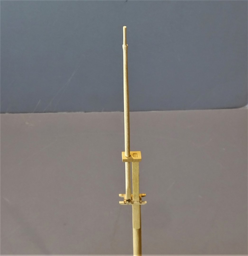
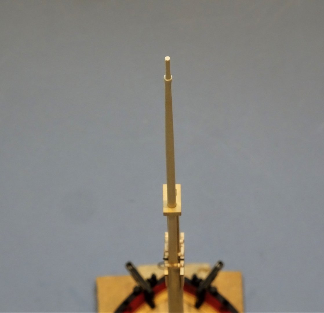
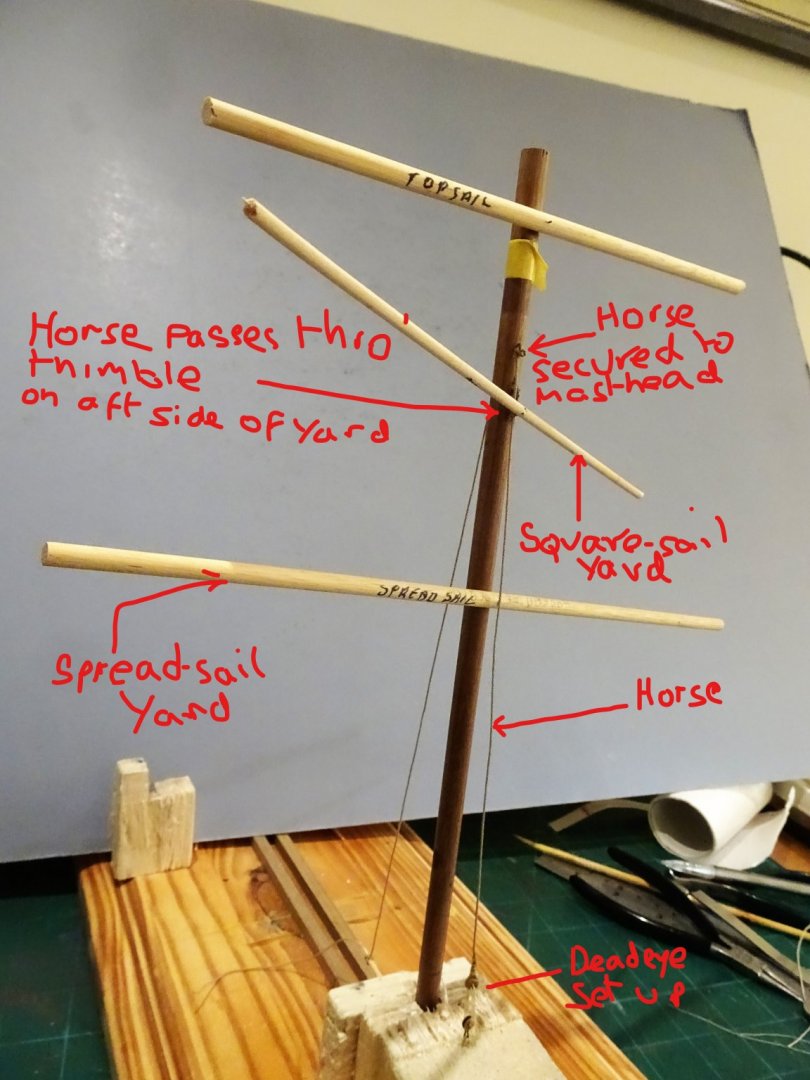
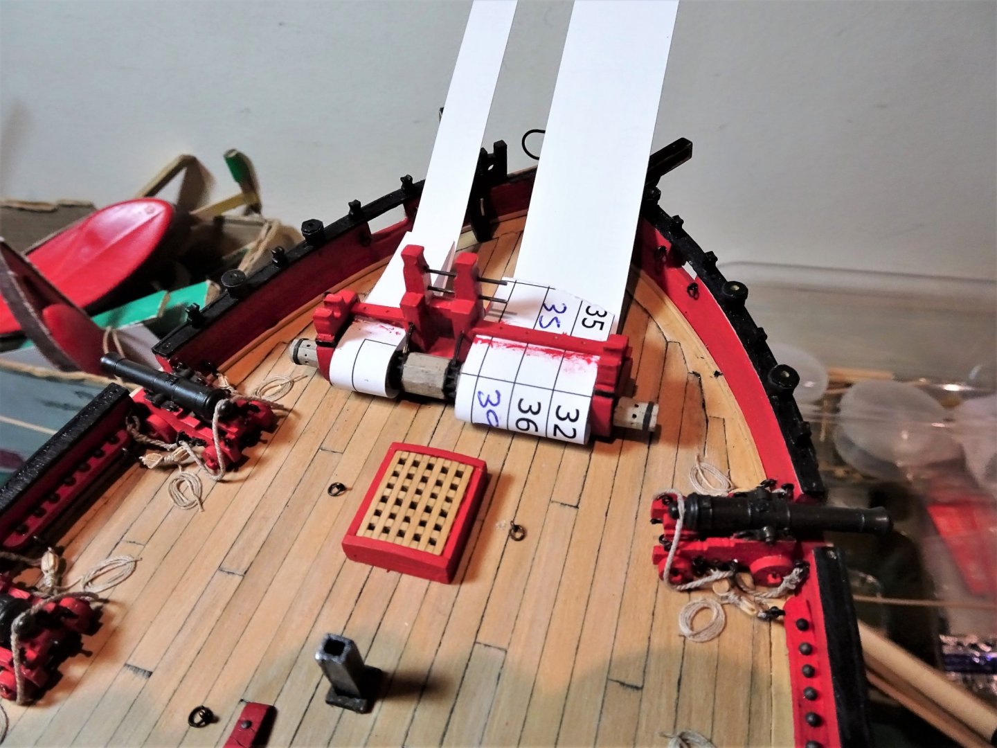
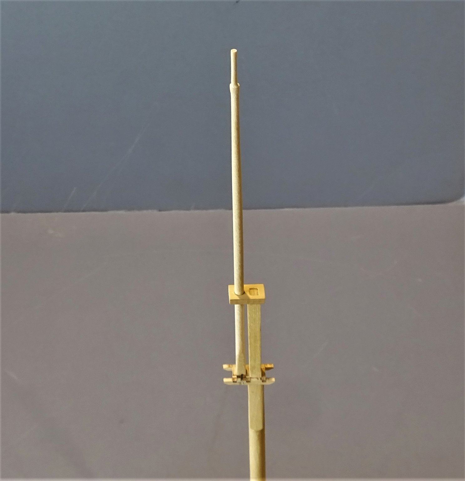
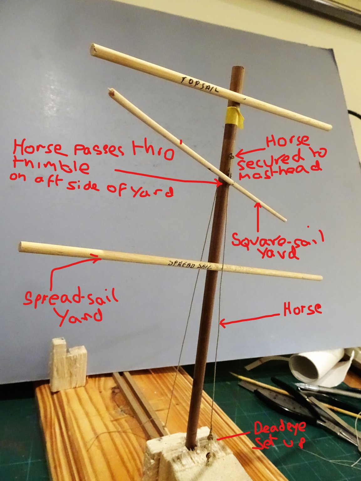
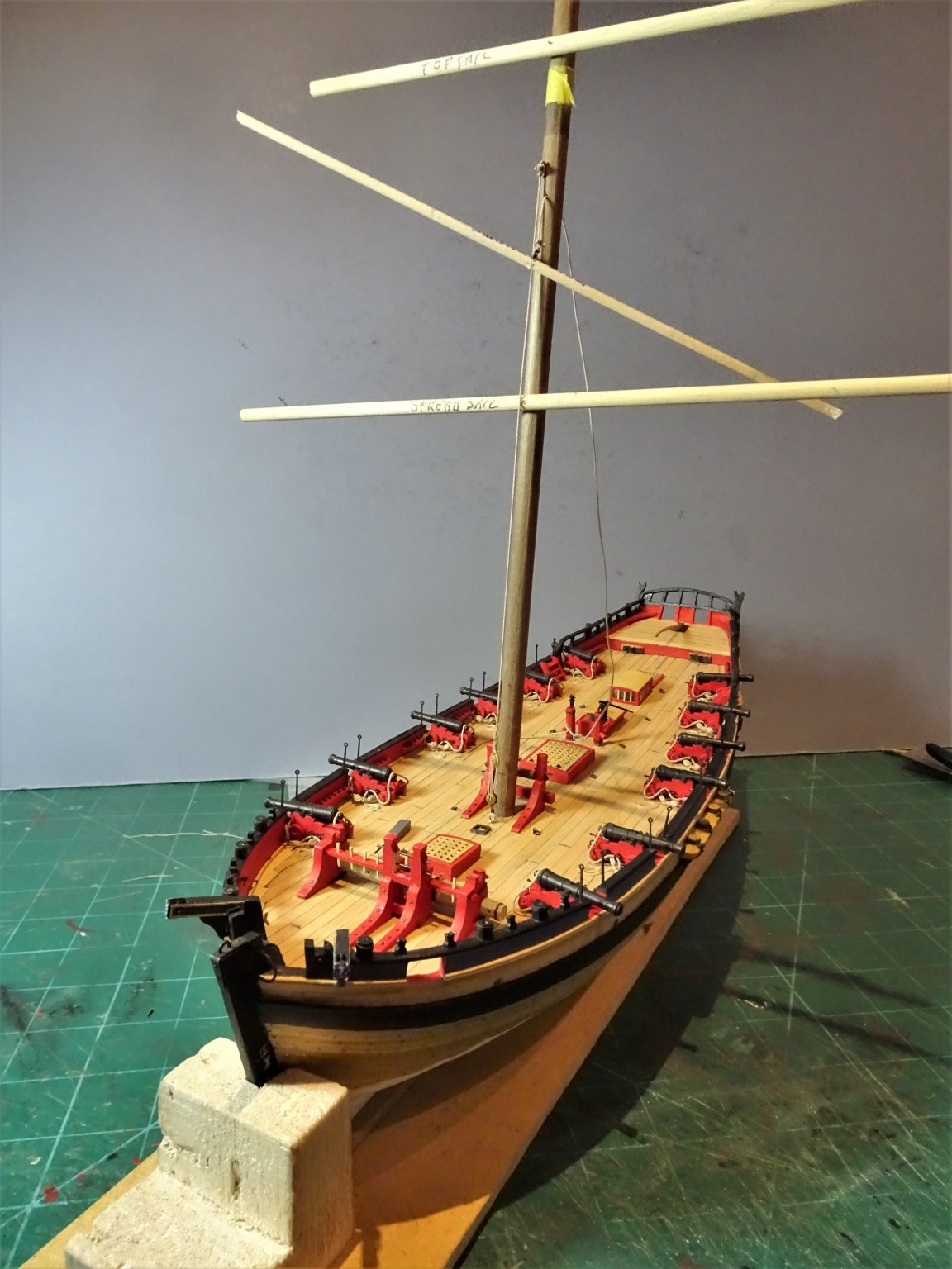
Post 51 Square-sails, Crossjacks, and Spread-yards - What’s it all about? To properly rig a cutter of this era these need to be understood, and I start out not being very clear at all. I am particularly interested in the Square-sail yard, a peculiarity of this type of cutter, also referred to as a Crossjack yard (by Steel). I am unfamiliar with both the yard and rigging associated with it. The Alert book narrative indicates that the Square-sail yard was set flying between the Topsail yard and the Spread-sail yard which held the foot of the Topsail. The Spread-sail yard in this case is what we would think of and performs the same function as the Crossjack Yard on a Square rigger. Horse for Square-sail yard. Steel lists a ‘horse down the mast’ associated with the Crossjack yard which for our purposes is the Square-sail Yard. The Horse has an eye splice at the upper end lashed to masthead. The Lower end is set up with deadeyes and lanyard to an eyebolt in the deck forward of the mast. Horse 5” circ. (0.63mm ø line) 7” deadeyes (3mm at scale) Marquardt, Eighteenth-century Rigs and Rigging provides the most comprehensive description and drawings. Topsail rigged vessels had the horse fitted forward of the crossjack yard*. The horse was led through an aft facing thimble on the Square-sail yard. Note: *I have taken this reference to the crossjack yard as relating to the Spread-sail yard, otherwise it makes no sense to me. In relation to the Square-sail or Crossjack Marquardt writes: Bent to the yard and comparable to a main or fore course, this sail was usually known as only as a Square sail, though Steel called it a crossjack. The latter name was used by Falconer only for the sail carried on the crossjack yard of a three masted ship, and he commented ‘this sail, however, has generally been found of little service and is therefore very seldom used.’ The Square-sail was only bent to a crossjack yard if the vessel did not carry a square topsail (Alert did) If a topsail was set, it was bent to an extra yard known as a square-sail yard, or club yard, which was hoisted up to the crossjack yard. In vessels with only a Topgallant mast stepped, (as with Alert) this yard was hoisted past the crossjack yard to below the hounds. The square-sail frequently had a bib to fill the space left by the deeply roached topsail. Use of a Horse is not mentioned in either the Alert book or the Kit rigging instructions. If a horse is to be fitted, then an eyebolt will be required at the foot of the mast to secure the deadeye. I mocked up a mast/yard arrangement to clear the set up in my mind and establish the position for the lower deadeye on the deck. 4213Li The Square-sail yard can thus be lowered to the deck, running down the horse. 4220 I trial fitted the arrangement on the model and I think it works. 4217 4215 The deadeyes can be made up off the model and be hooked or seized to a deck eyebolt which I can now put into place. B.E. 05/01/2020


- 335 replies
-
- 13
-
-
- alert
- vanguard models
- (and 1 more)
-
I'm not sure that the paint has special properties and I think they have been discontinued, probably on ecological and health grounds. I bought a set of the Floquil marine colours many years ago, one of which was the Verdigris. The others had interesting names like Tallow Coat, Pine tar oil, Weathered Manilla, and Orange Ochre. I don't think you would have much trouble finding a substitute Verdigris paint, it is widely used to create an aged copper look in the arts and craft world. B.E.
- 126 replies
-
- 1
-
-
- le superbe
- heller
- (and 2 more)
-
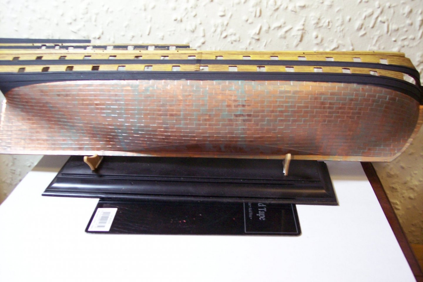
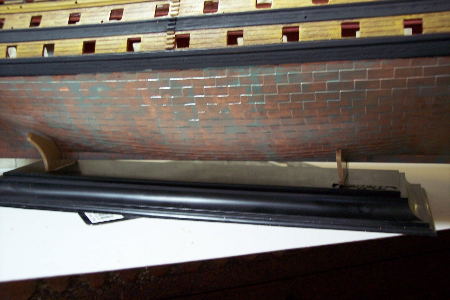
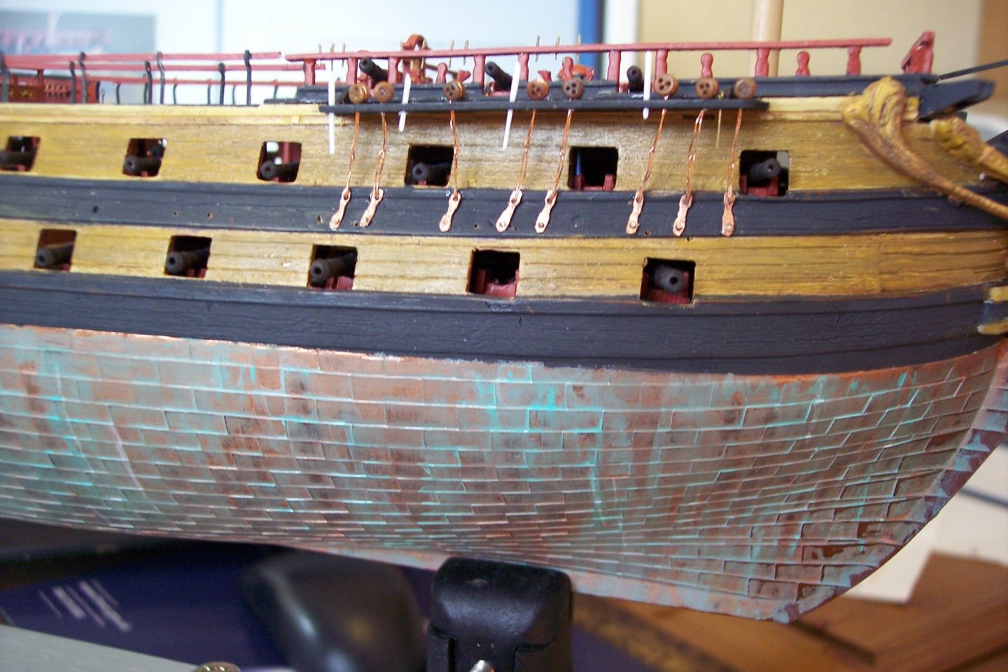
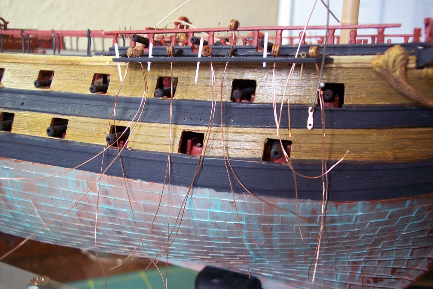
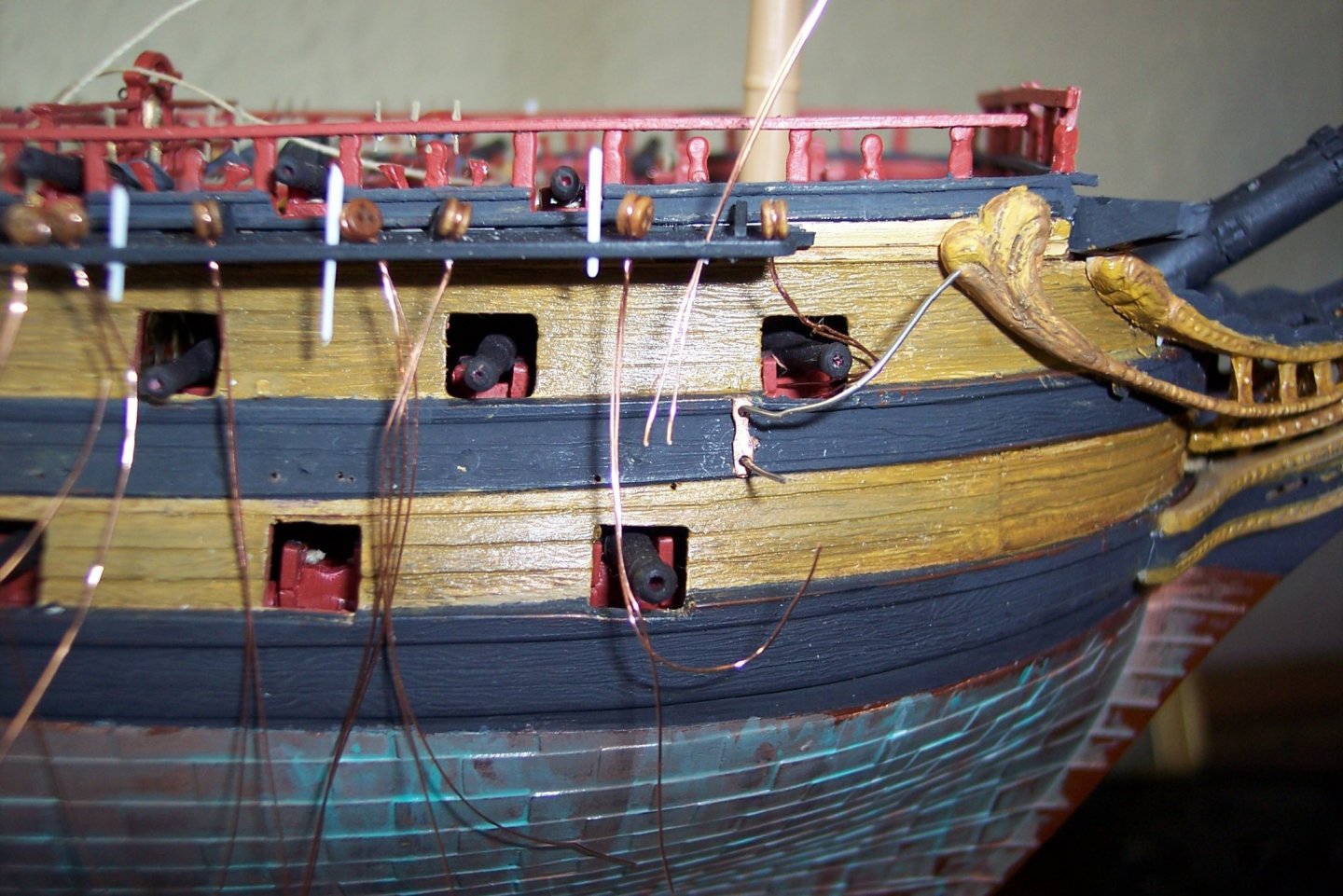
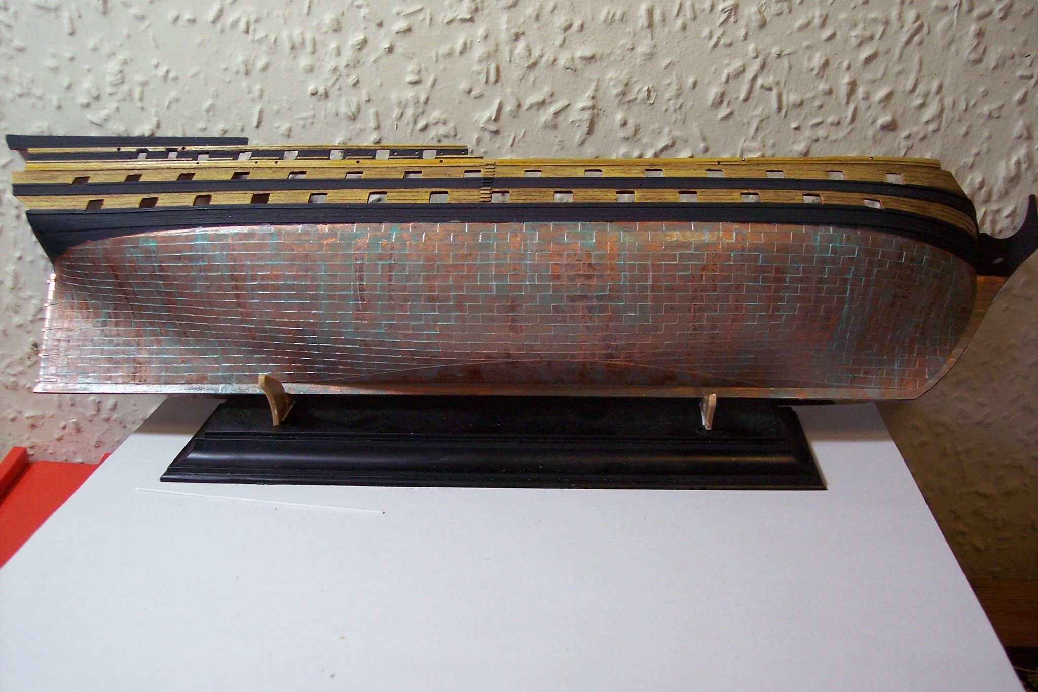
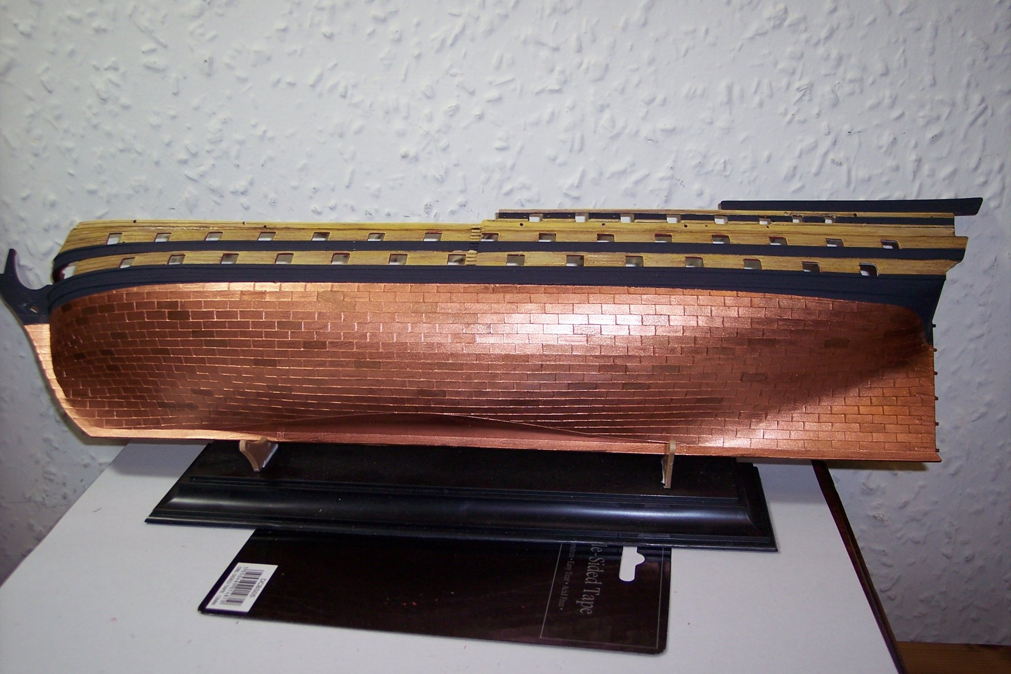
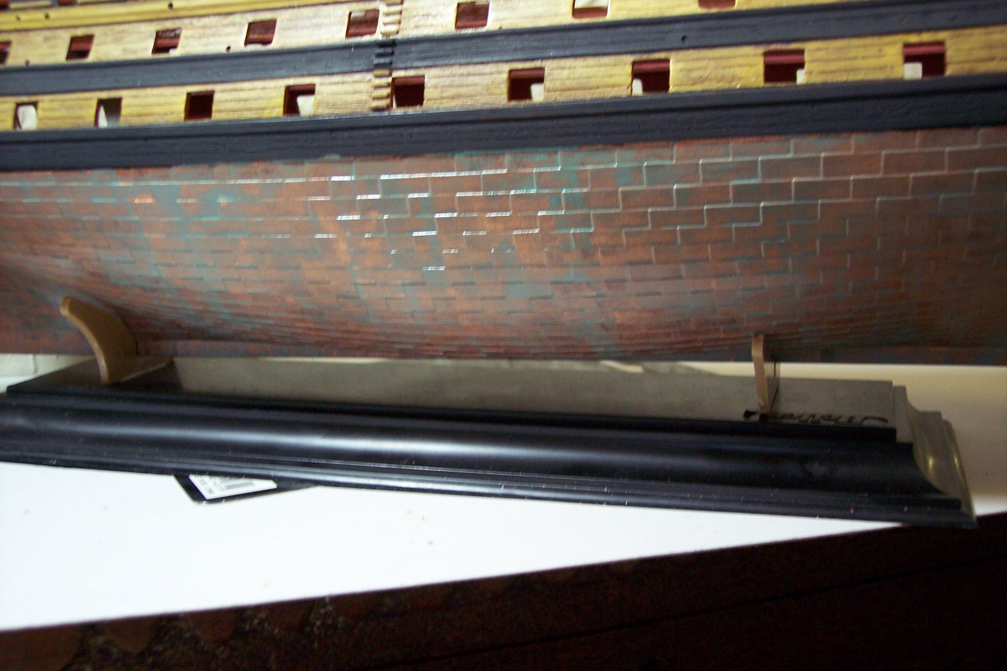
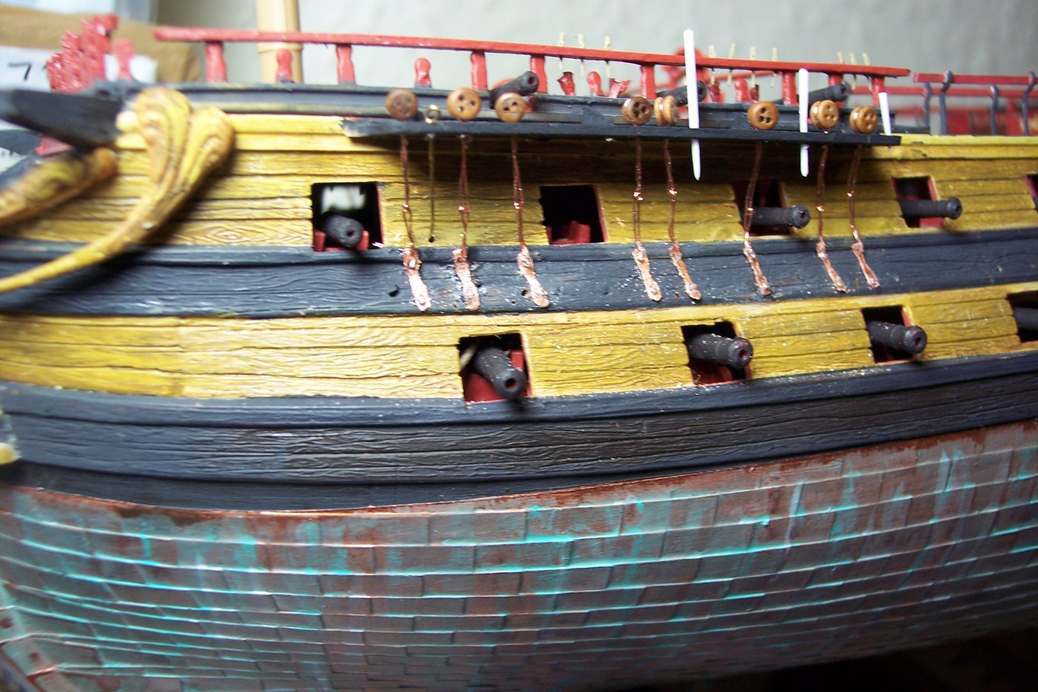
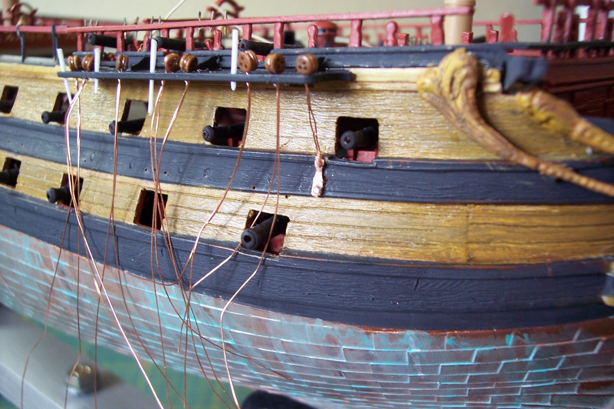
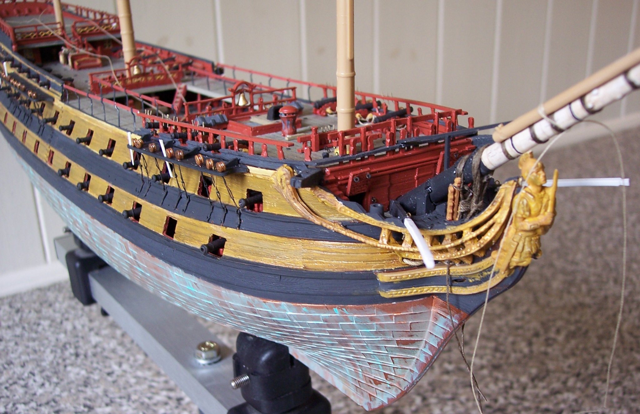
Hi Shipman, This is the section I wrote on the original log regarding hull weathering. The Verdigris effect looks nice on models but remember that in reality it would only occur where the copper is exposed to the air, ie above the waterline. For a ship in the water the copper would be a fairly uniform dull brownish colour. Note: All the paints used were spirit based.. Weathering the hull The copper plating was painted using Humbrol No 12 copper. This was followed up by painting individual plates slightly different shades of copper at random. 005 Much thinned down Floquil Verdigris was used for the initial wash, and using downward strokes was all but removed to allow the basic copper to show thro’ but dulled down. 007 Using a fine brush neat Floquil Verdigris was brushed down in vertical lines and over brushed with Admiralty dull white. 002 White spirit was then liberally brushed down over the paint to create the effect. 009 Once dry, a 5/0 brush was used to apply a little more dull white in fine downward strokes. This is more or less the result I am after, but there is always the temptation to fiddle with the weathering long after the initial application has been made, and touch up work will be required once the hull halves are put together. B.E.


- 126 replies
-
- 6
-
-
- le superbe
- heller
- (and 2 more)
-
Thank you Shipman, doing this build was certainly testing due to the scale and ageing eyes, I don’t think I could do it again. I’Il have a look thro’ my files and see what I have recorded about the coppering finish. B.E.
- 126 replies
-
- 2
-
-
- le superbe
- heller
- (and 2 more)
-
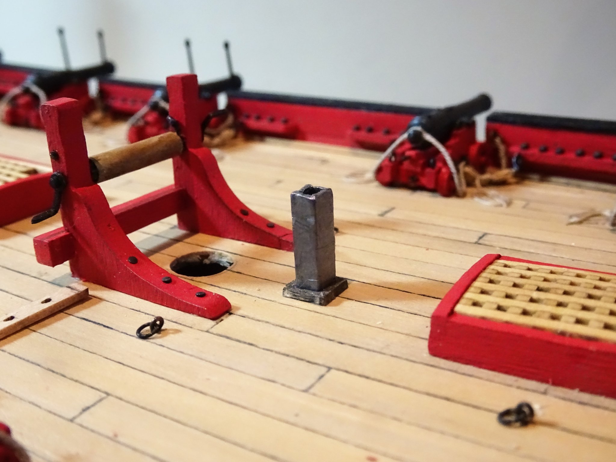
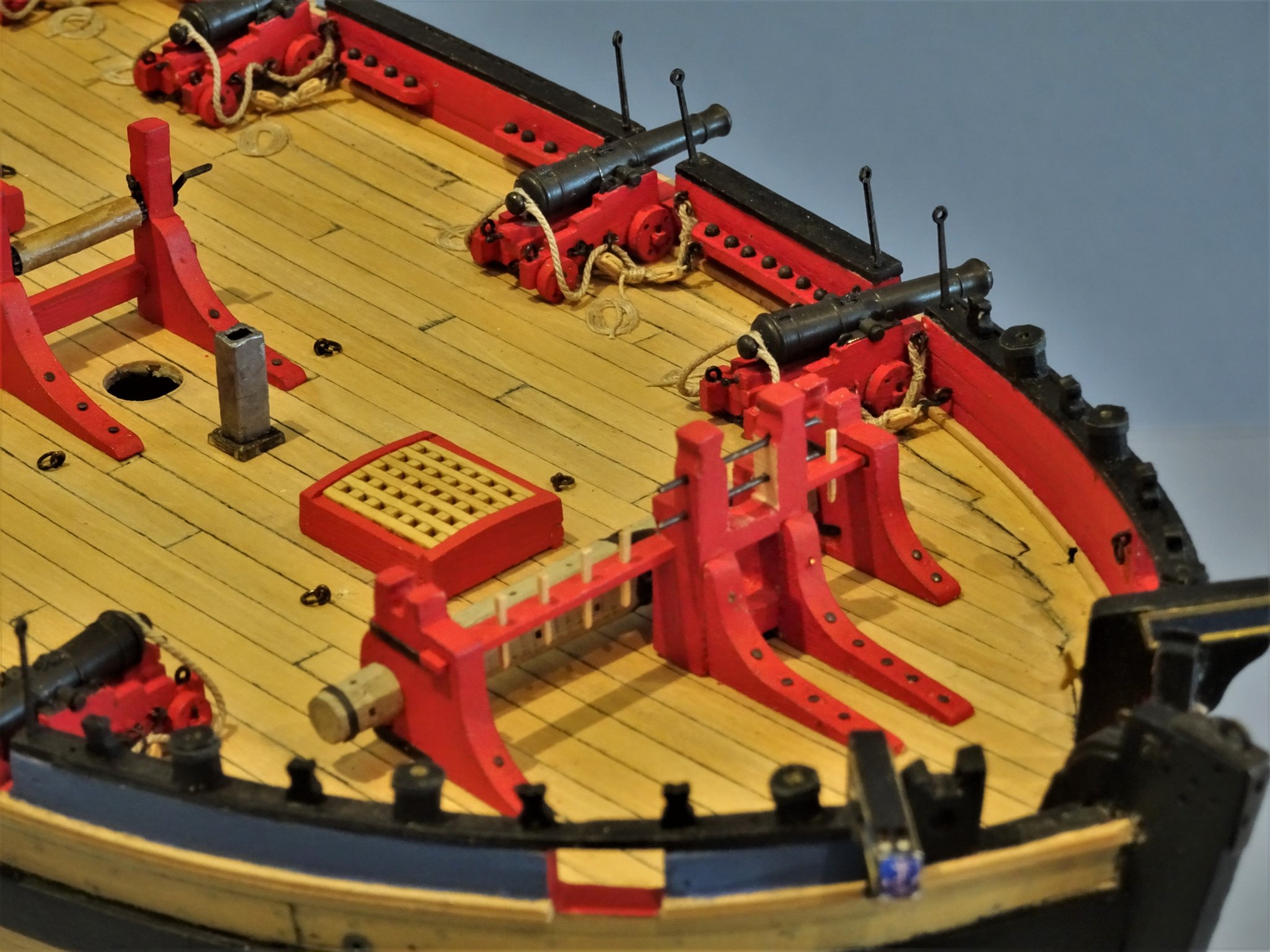
Post 50 Draught markings This is an opportune time to add the draught markings down the stem. I found these quite tricky things to apply, getting the spacing and orientation looking right. 4153(2) They were chemically blackened and once fixed a weathering powder mix was sparingly applied. Galley chimney. 4136 I remodelled this from a piece of Boxwood sheathed in lead foil. The Guard rope stanchions are not immediately required, but a convenient time to blacken and trial fit them. 4155 To my eye the provided kit stanchions looked a little heavy for the scale. Fortunately, I had some stanchions left over from my Pegasus build which are finer in profile and I used them in preference. They will be put aside until the rigging is completed; they present as perfect snag magnets. Carrick Bitt pin racks (parts 57,58) These fit thro’ slots in the Carrick Bitts and in the Pawl Bitt strongback. 4128(3) Came across a little problem here; when I came to fit these, instead of running level between the two bitts they angled upwards because the slot on the Pawl bitts was higher than on the Carrick bitts. I have no idea how this has come about; I had checked the fit during the assembly stage, and it seemed ok, or at least I thought it did. The windlass assembly is firmly fixed to the deck, so removal and re-working was not an option. 4143 A bit of very careful scalpel work on the Pawl bitts was required, followed by some filler and re-painting. Inclusion of these pin racks stems from the Alert book and is duplicated in the kit. Still not sure about them on cutters of this period but there is a need for them when it comes to rigging so I follow suit. The kit provides brass etched belaying pins which didn’t suit my eye. 4177 The Alert book drawings show what are termed belaying posts, more rectangular in shape than a traditional pin, and I opted for these instead using some 1mm Boxwood section. 4166(2) I need to shape the posts a little more and test them for strength. 4174(2) Time to look at the masts and yards. B.E. 03/01/20
.thumb.JPG.be7121e4f165b37f22546aae521a3091.JPG)

.thumb.JPG.30ba2a63194b37b1a685ca4f55b5a1a8.JPG)
.thumb.JPG.9e7c73169e86189ef80dec4671ef9bf0.JPG)
.thumb.JPG.2ecf8c03f10cd28582e277f2d0fe8d7d.JPG)

- 335 replies
-
- 19
-
-
- alert
- vanguard models
- (and 1 more)
-
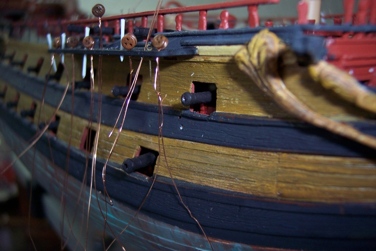
Hi rk, This is the Chapter from my original log on the subject. Faking it at 1:150 This is the stuff I used to recreate the deadeyes, chains and Preventer plates on the French Seventy four. 015(2) The deadeyes are 2mm Amati code 37160 The plates were fashioned from Amati copper hinges code 4130; the source items and the formed plates can be seen on the black background. 34 gauge beading wire was used to form the strops and chains. Telephone wire was used to position the plates whilst fixing, and to form the bolt heads. Brass black /and or paint was used to colour the chains and plates. Caldercraft professional thick super glue used to secure the plates and chains to the hull. Tools used consisted of a pin vice with 0.4mm drill bit, and pliers to hold and cut the plates whilst forming, and nip off the chains. The plates were held in the pliers, and were formed using needle files A fine brush will be used to colour the chains. 009(2) Here the chain wire is used to mark the position of the top hole for the Plate. 10 Here the chain wire has been hitched to form the first link. 15 The plate is held in the first hole to mark the position of the lower hole. 19 The plate has been secured by telephone wire super-glued into the lower hole It will be nipped off to form the bolt head. 30 Here the chain ends have been secured and super-glued thro’ the top hole of the plate and into the hull. 11 The completed run of chains and plates on the Starboard Fore channel. 7(2) 36 Regards, B.E. 03/01/20

.thumb.JPG.a59c21650dac743dc30bb136c5376467.JPG)
.thumb.JPG.f15c73c6e1e824e00b33a6d0333eeb86.JPG)


.thumb.JPG.5ba80ceb04ed154a5d8b558a5a1e09c6.JPG)
- 126 replies
-
- 4
-
-
- le superbe
- heller
- (and 2 more)
-
Great job Allan, Billing boat kits are old school, and what you’re doing takes some doing.😊 B.E.
-
Thank you Jim, much appreciated. 🙂 @ VTH - I'm sure you will enjoy this kit especially if you have the newer version with enhanced fittings. It's a good first planking subject, not too bluff in the bows. @ Dave - Thanks Dave, I'm always pleased when I reach this stage of a build. Hope things go well with Speedwell in 2020. Happy New Year Guys. B.E.
-
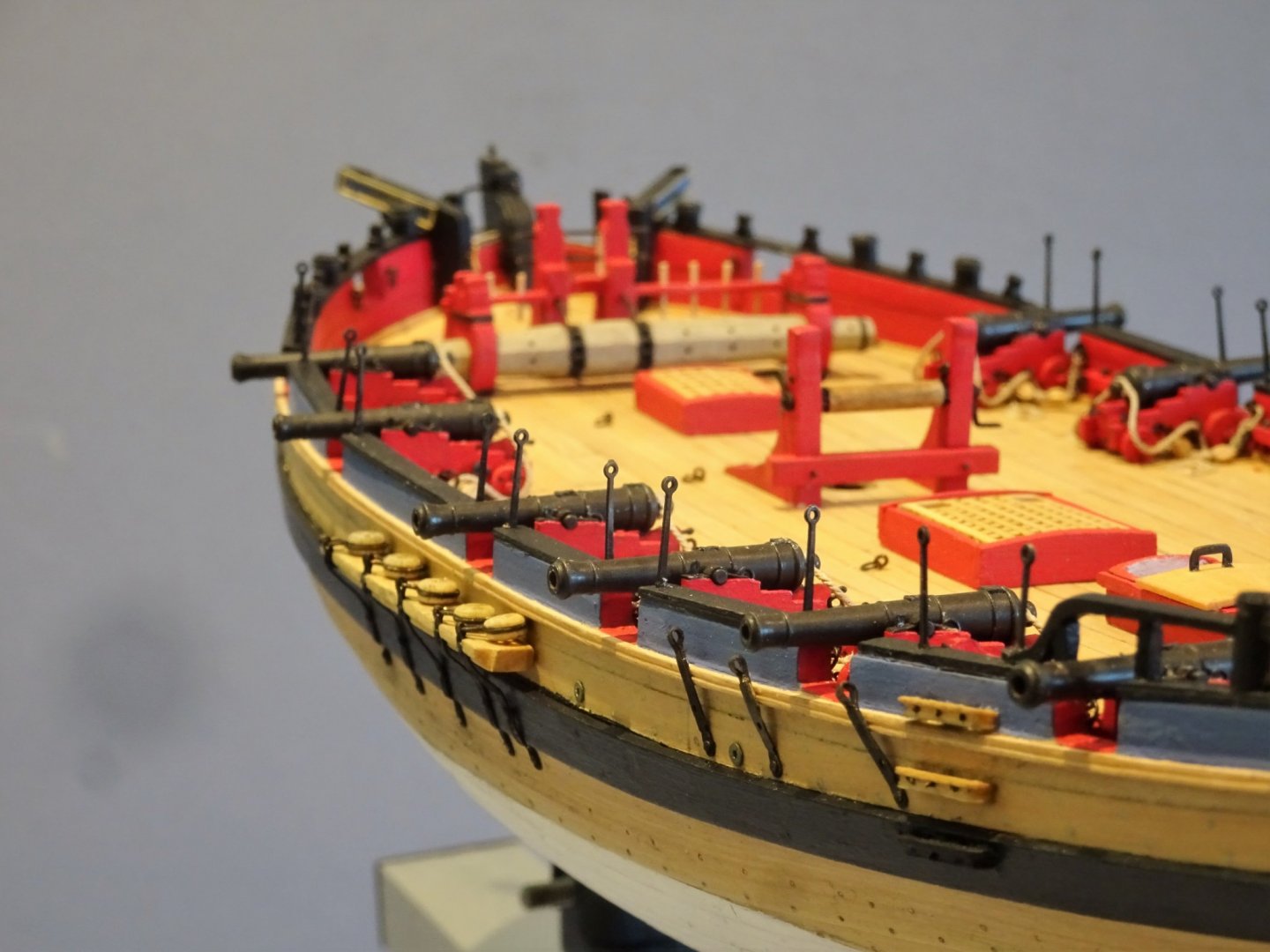
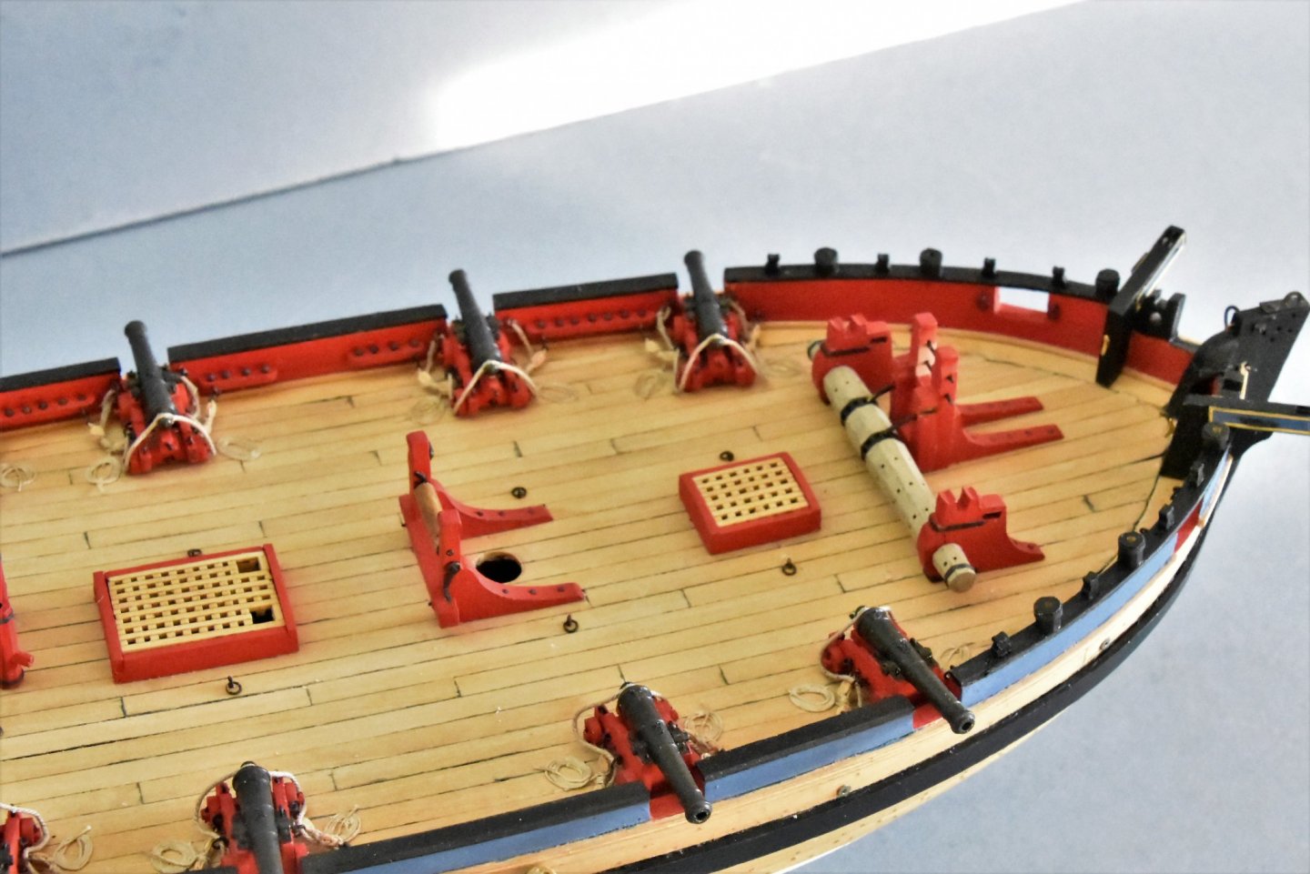
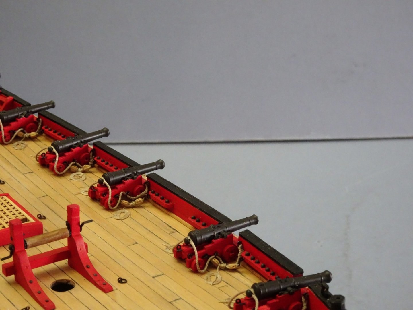
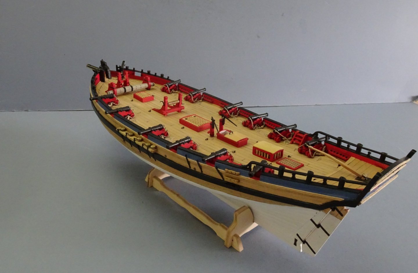
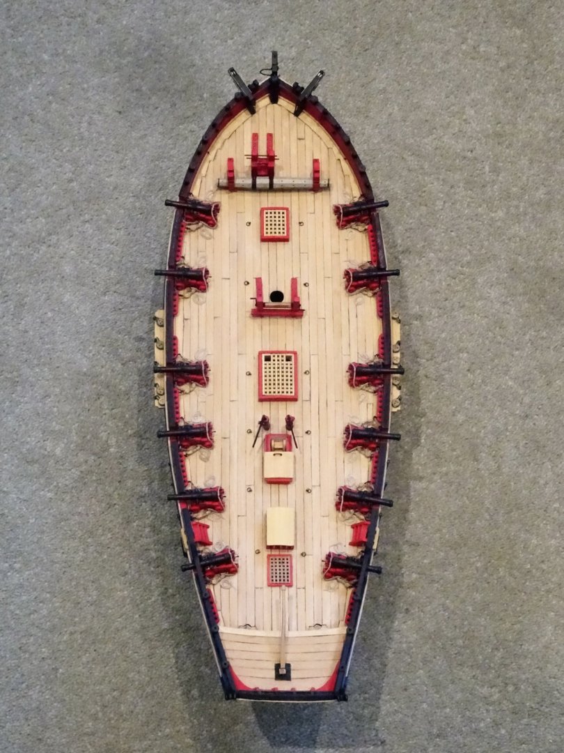
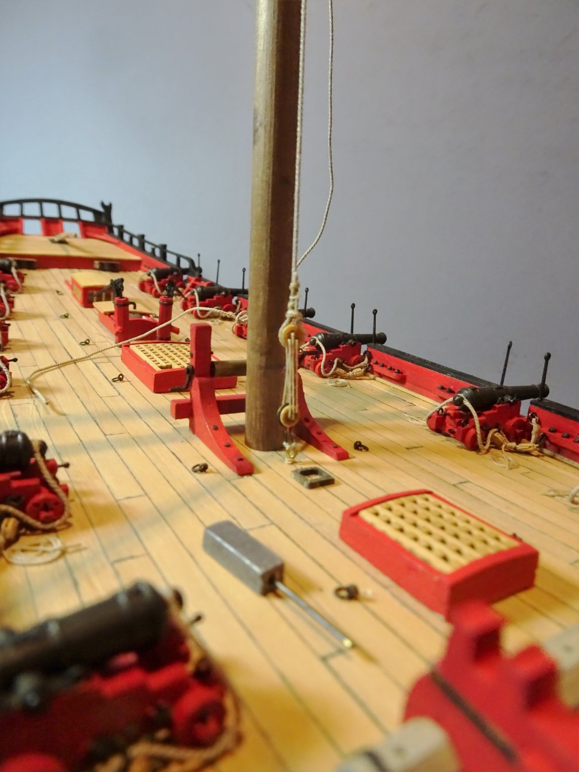
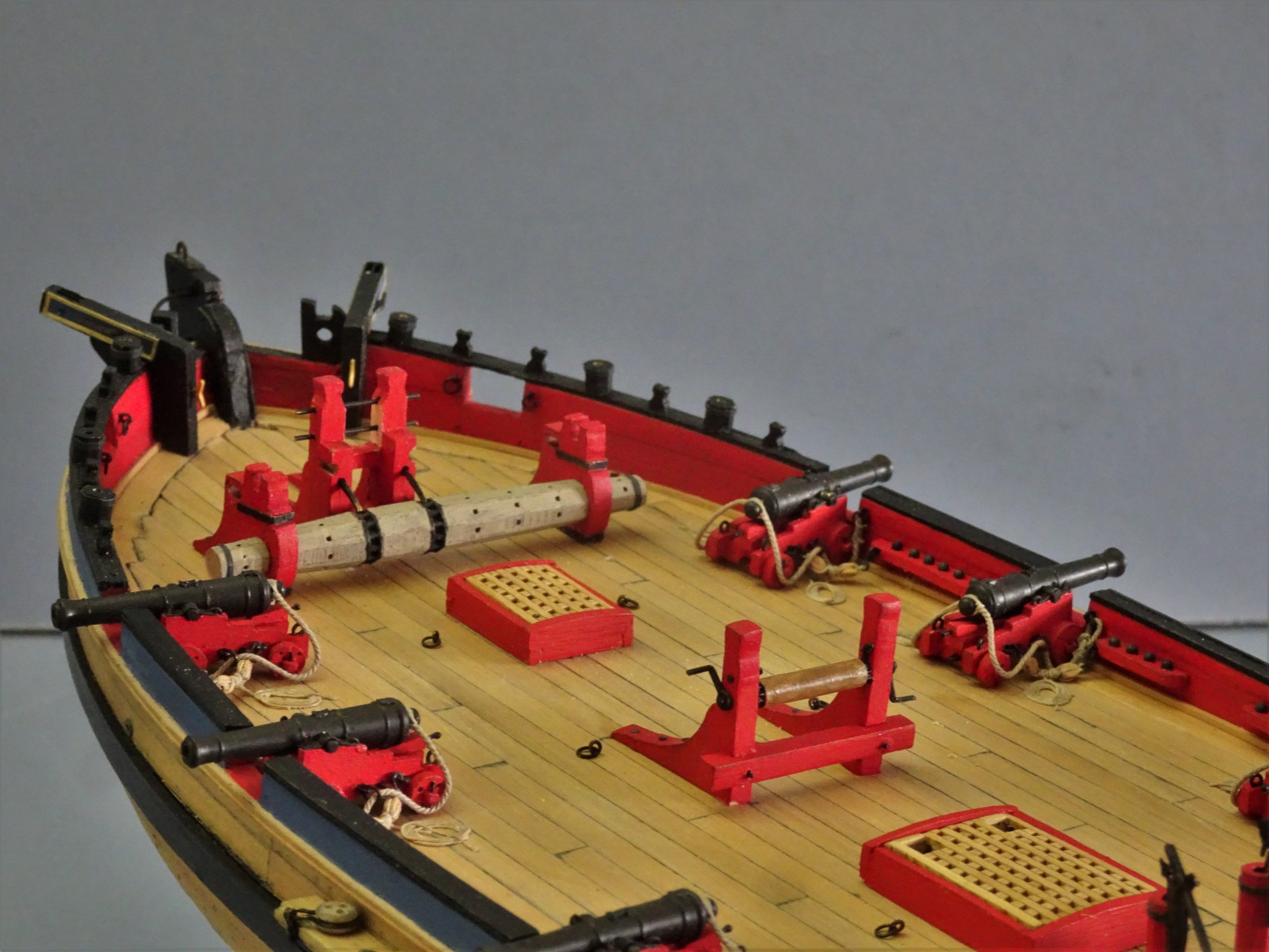
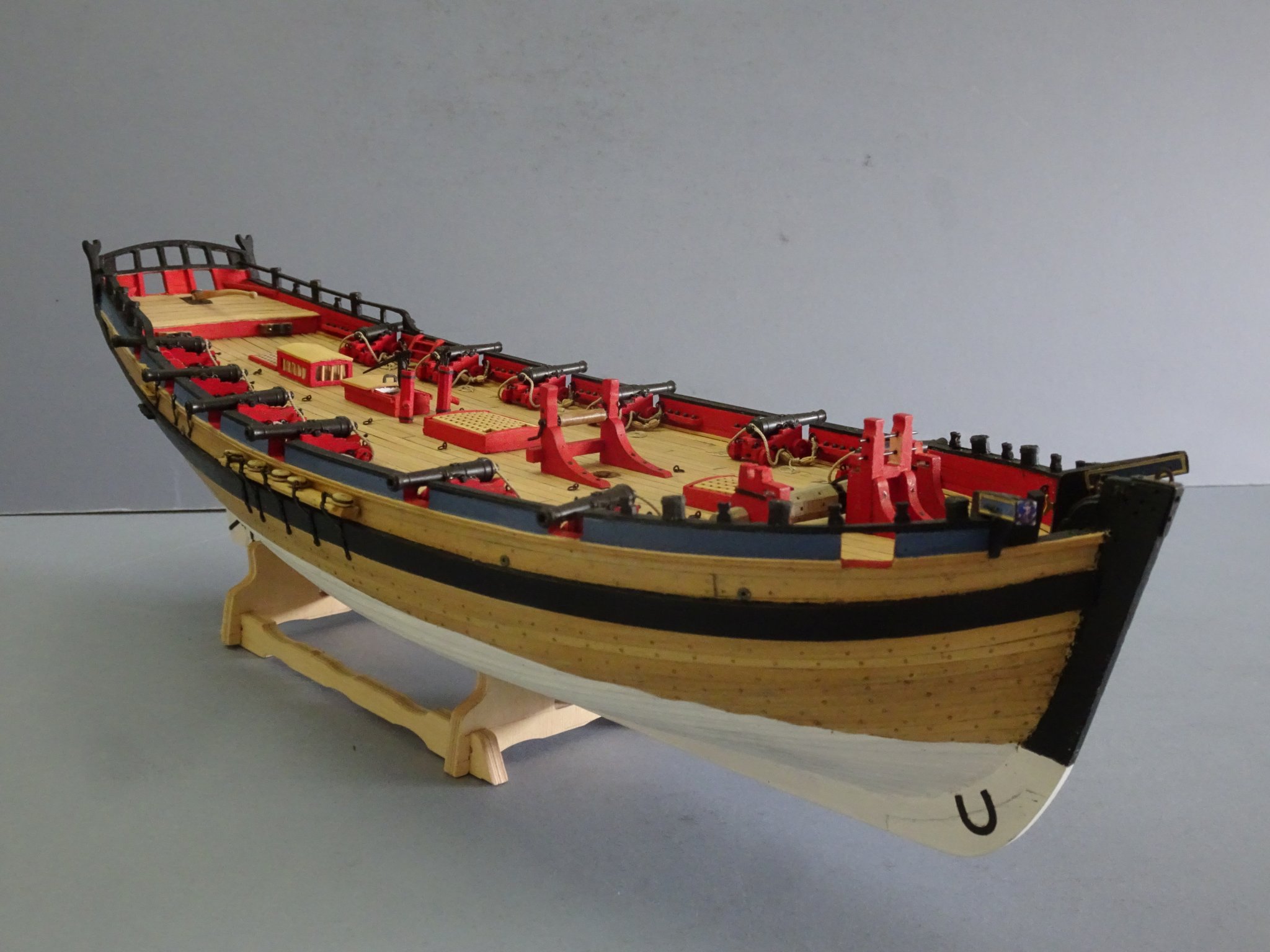
Post 49 Hull completion This post marks six months into the build and completion of the hull by the fitting of the gun side tackles and remaining deck fittings. 4089 4094 4084 4085(2) 7771 4097 4091(2) 4092 4090 7764(2) That’s it for 2019. Wishing my fellow MSW members successful modelling in 2020 B.E. 29/12/2019
.thumb.JPG.6126f52804031eadc69d9906f6be1bca.JPG)
.thumb.JPG.3b7748ee774a3487c0eb2cdbf801f42e.JPG)

.thumb.JPG.ff7d0be78a188cd61df93f5801f1d7b8.JPG)

.thumb.JPG.0888dea4d7b5b58ae23aeb2e5cb6f0dd.JPG)
- 335 replies
-
- 28
-
-
- alert
- vanguard models
- (and 1 more)
-
You're welcome Skip, glad you found it of use, headworks are tricky things. Cheers, B.E.
- 366 replies
-
- 2
-
-
- pegasus
- victory models
- (and 2 more)


.JPG.ad4caaf0d443f17a52e0c0482a4770ec.JPG)
.JPG.c19e9420e6887cfb170d1888640af868.JPG)
.JPG.edac668257e7e7ae3fc0a7f785be4381.JPG)

.JPG.5db5d964c91db6645de48c777b09984e.JPG)

.JPG.afe2af4caad8436150eb33d8fb1b1e58.JPG)
.JPG.d03b6d3c29e3bdb304793ed289ffcf1c.JPG)
.JPG.ed87d8b53a83cdc373ded805ed7fb726.JPG)
.JPG.c39e4e9af9a69b5dd0c25544f07cad78.JPG)
.JPG.6d20f4f29ead482fc17ac7aae50812aa.JPG)
.JPG.720f63d33a3f51a029deb3ccfa103244.JPG)
.JPG.06ab9921c8c0e50938b957ac0c403e72.JPG)
.JPG.8e54afd5ad576880974c4c2b8fbad515.JPG)

.JPG.879020b897029cecab80785de63da180.JPG)
.jpg.2a22470a382a7cff34a1e204c1e17f08.jpg)


.JPG.efb5fed52a34e8d45a1d56185c434381.JPG)

.JPG.539580ed0ba1220122fe095138995722.JPG)

.JPG.caa0b724f9087ceda35f53a5b4e6862b.JPG)
.JPG.93c6c170355ba636df73a8c2acc33af0.JPG)
.JPG.d7e1cdeb15532be8d287559429e59c06.JPG)


.JPG.6bd96edf814f65c9340735e437d29f9d.JPG)


.JPG.3be3ab3d28e083f369873fde59307706.JPG)
.JPG.6cb8b982932f7ed23b8ed444df4ec51a.JPG)


.JPG.b5f6e727e8390727b297099c00b1afae.JPG)

.JPG.127149709e1d4ed0f3f53ac06ec8dfde.JPG)
.JPG.55355cc5e5d200cf34b6f9e2939b24d2.JPG)
