
HOLIDAY DONATION DRIVE - SUPPORT MSW - DO YOUR PART TO KEEP THIS GREAT FORUM GOING! (Only 20 donations so far - C'mon guys!)
×
.JPG.ca33079f5815b861e67b9c2cccd37982.JPG)

Blue Ensign
-
Posts
4,564 -
Joined
-
Last visited
Content Type
Profiles
Forums
Gallery
Events
Everything posted by Blue Ensign
-
 Thanks Glenn, yes it is the Cheerful plan, I think they make great 'art' works in their own right. I also have the Pegasus plan framed in the same manner. I look forward to seeing your completed Cheerful hull, I think you will be pleased it. I love the look of the Cheerful hull, with its high quality wood finishes, and minimal contrasting paintwork. For me the next phase of a build - the fitting out, is the part I enjoy most. B.E.
- 261 replies
-
- 3
-

-
- muirneag
- vanguard models
- (and 2 more)
-
Enjoyed reading through your log JpR, love the colour combinations you have achieved, and the look of her. I would be very happy to have produced your fine little model. Nice work 👍 B.E.
-
Thanks Martin, My bench was store bought many years ago, it does have and end vice as well but not enough room to fit it. Those dog holes will be useful for some functions, but I had to buy a thick surface protector so I don't loose bits when using it for more general work. @ Bob, The Harold Underhill plans are widely available for around £10 each in the UK. As for the name; as a mere Sassenach, I would hate to presume on the Gaelic pronunciation of Muirneag. I've never heard it spoken, but would hazard a phonetic guess at Moor'nag. 🤔 Would be interesting to know from someone who's heritage lies north of Hadrian's Wall, but even north of Hadrian's Wall, there's north and then again north. 😃 B.E.
- 261 replies
-
- 6
-
-
- muirneag
- vanguard models
- (and 2 more)
-
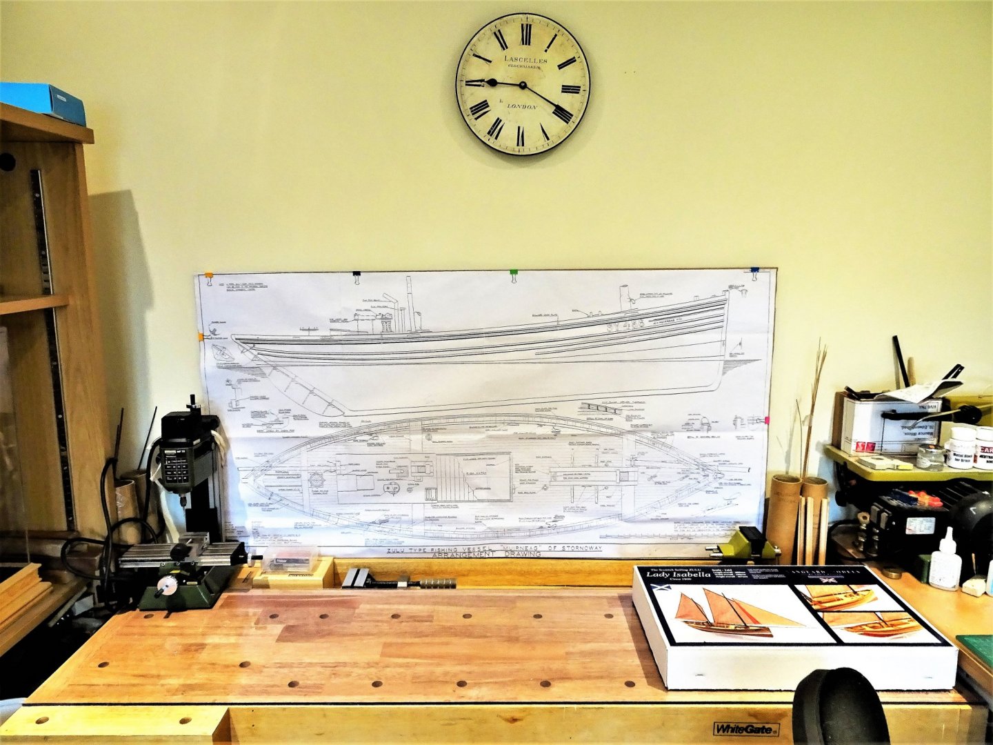
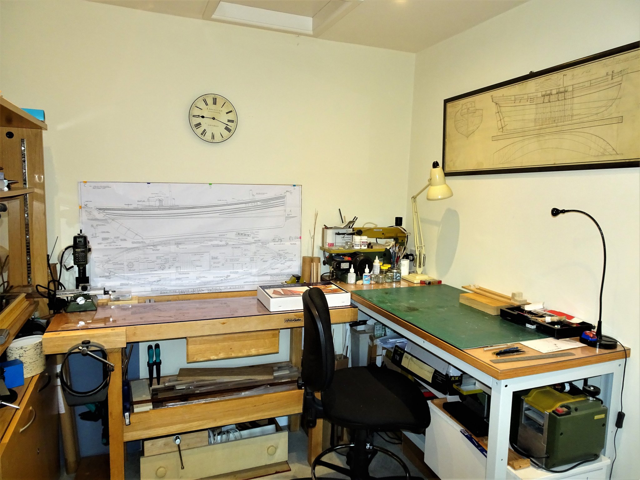
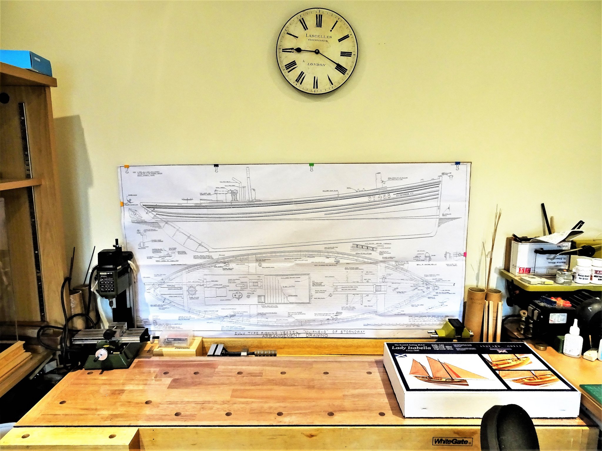
So the work space has been cleared up. 6629 It won't look this tidy again until completion of the Muirneag project. 6632 I'm clearing out the garage, so I've also taken the opportunity to move my woodworking bench into my office to give me more working surface. Must have been destined as it turned out to be a perfect fit. 🙂 On with the show. B.E.

- 261 replies
-
- 20
-
-
- muirneag
- vanguard models
- (and 2 more)
-
Very nicely done Doug, like the shaping of the gratings, and the guns look to have turned out just fine. 👍 B.E.
- 40 replies
-
- 1
-
-
- sherbourne
- caldercraft
- (and 1 more)
-
Interesting subject and a fine looking model Don, she looks great on your mantel shelf. 👍 B.E.
- 36 replies
-
- 1
-
-
- calypso
- billing boats
- (and 1 more)
-
Cheers Guys for your interest.🙂 @ Yves – Chris has done a fine job with this kit which stands very well in its own right, and I’m impressed with the level of small detail provided. Inclusion of such items as the coal bunker hatch, pump deck plate, additional hook positions for the Fore tack, roller for the warp hatch, and the distinctive horizontal wheel, pay testimony to the research Chris has put into this kit. I don’t really think additional wood sheets are required, it’s more a question of tweaking the layout to suit Muirnead. My least favoured detail are the unconvincing rings for the fish hatch boards, I didn’t include them on the Fifie, and they are not shown on the Muirneag plans, or actual photos of sailing drifters, as far as I can see. I can sort of see why perhaps Chris included them given his target market, some modellers may like to see them as a feature, and it avoids the question – shouldn’t there be hatch rings. @ John – The story of working these boats is fascinating, and I’m full of admiration for the skill and bravery of the fishermen who handled these large luggers in the less than desirable conditions of the North Sea. A very hard life indeed. @ Bob – Having all that reference material is of great help when undertaking a project such as this, but I’ll consider myself lucky if I get anywhere near to those wonderful scratch builds. Thanks to Chris he has provided the makings to have a go. @ Grant – Thank you for your support, I’ll try to do it justice. 👍 B.E. 13/08/20
- 261 replies
-
- 7
-
-
- muirneag
- vanguard models
- (and 2 more)
-
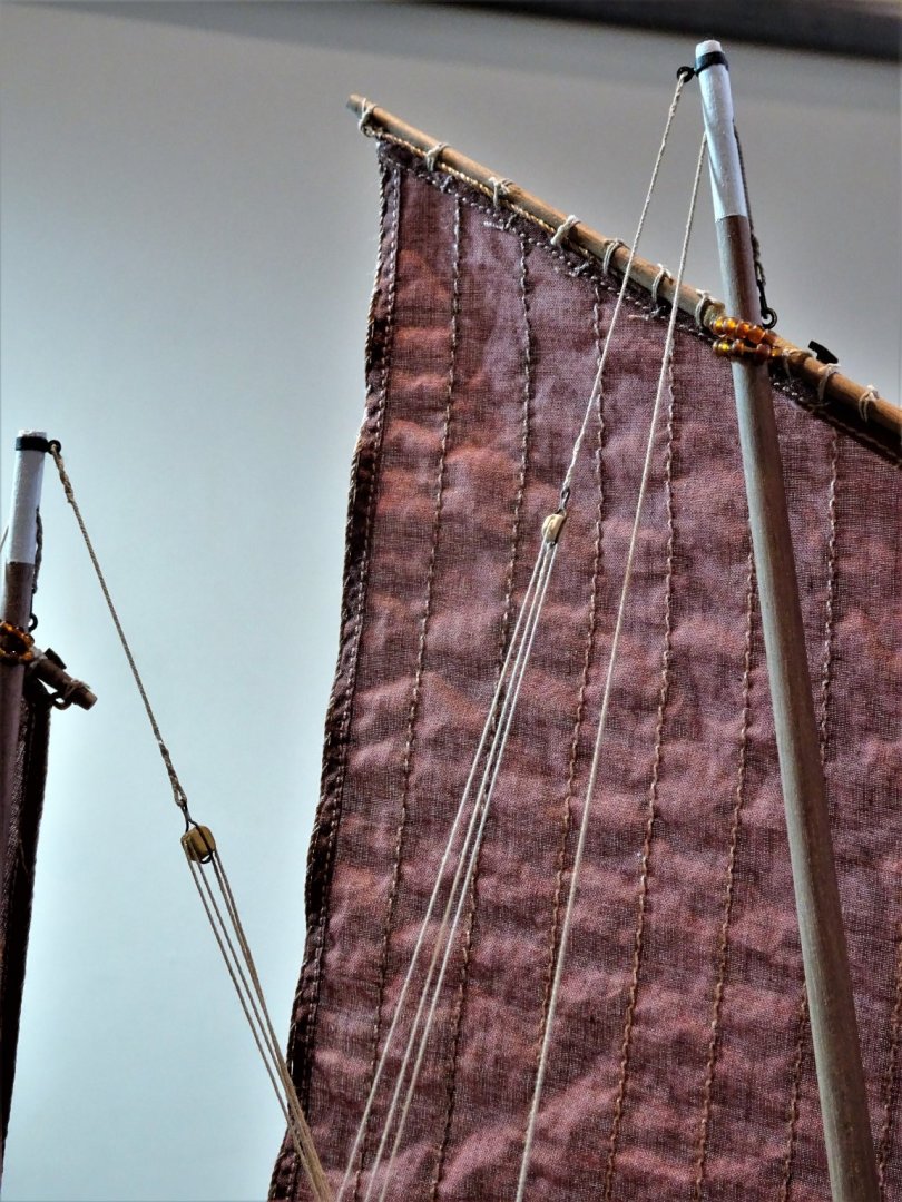
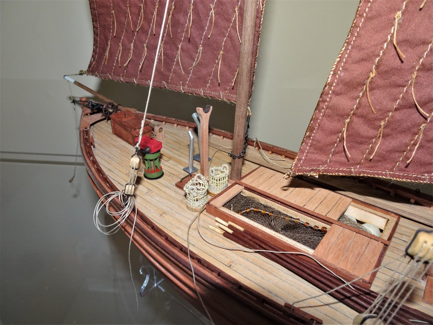
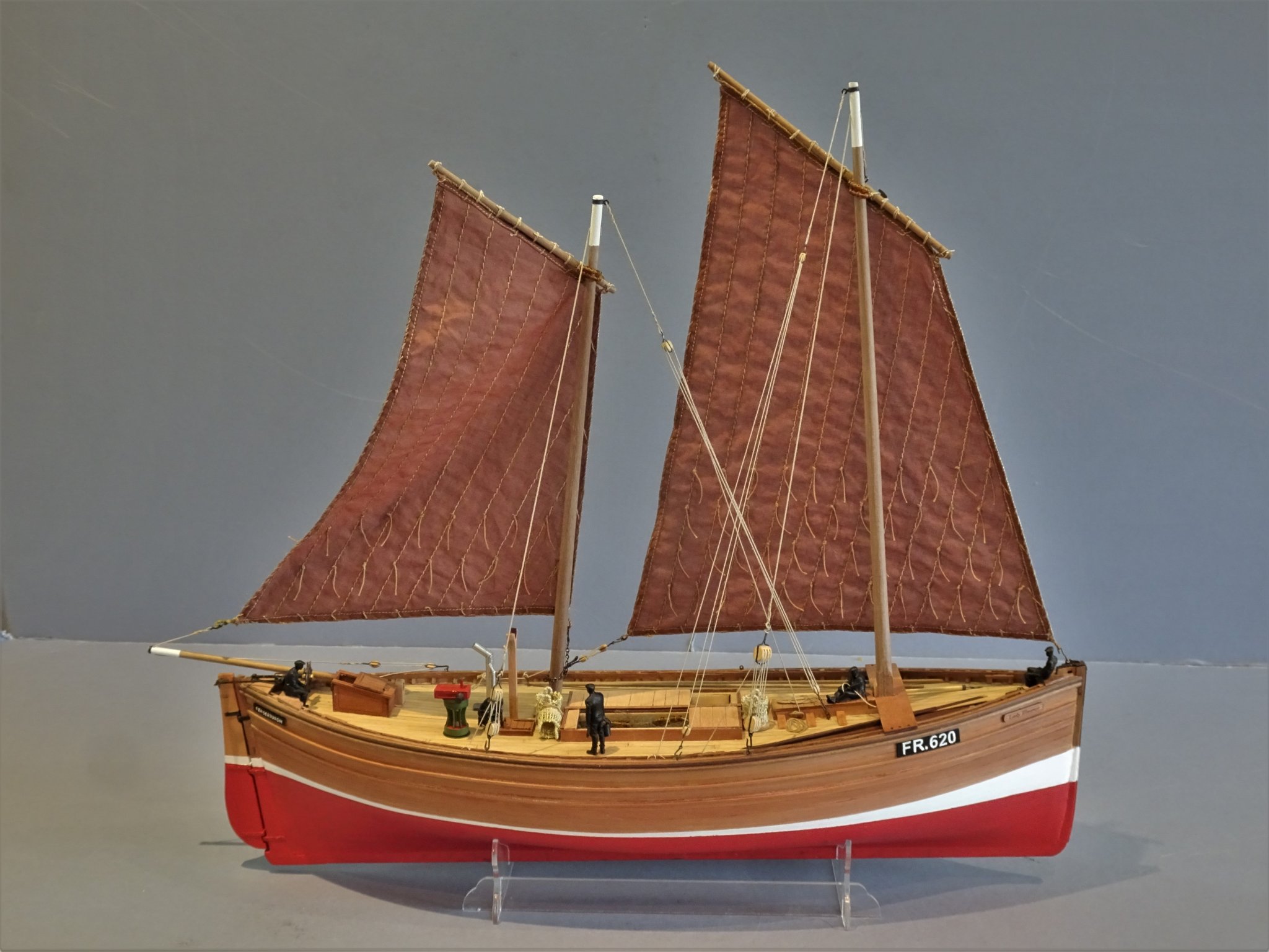
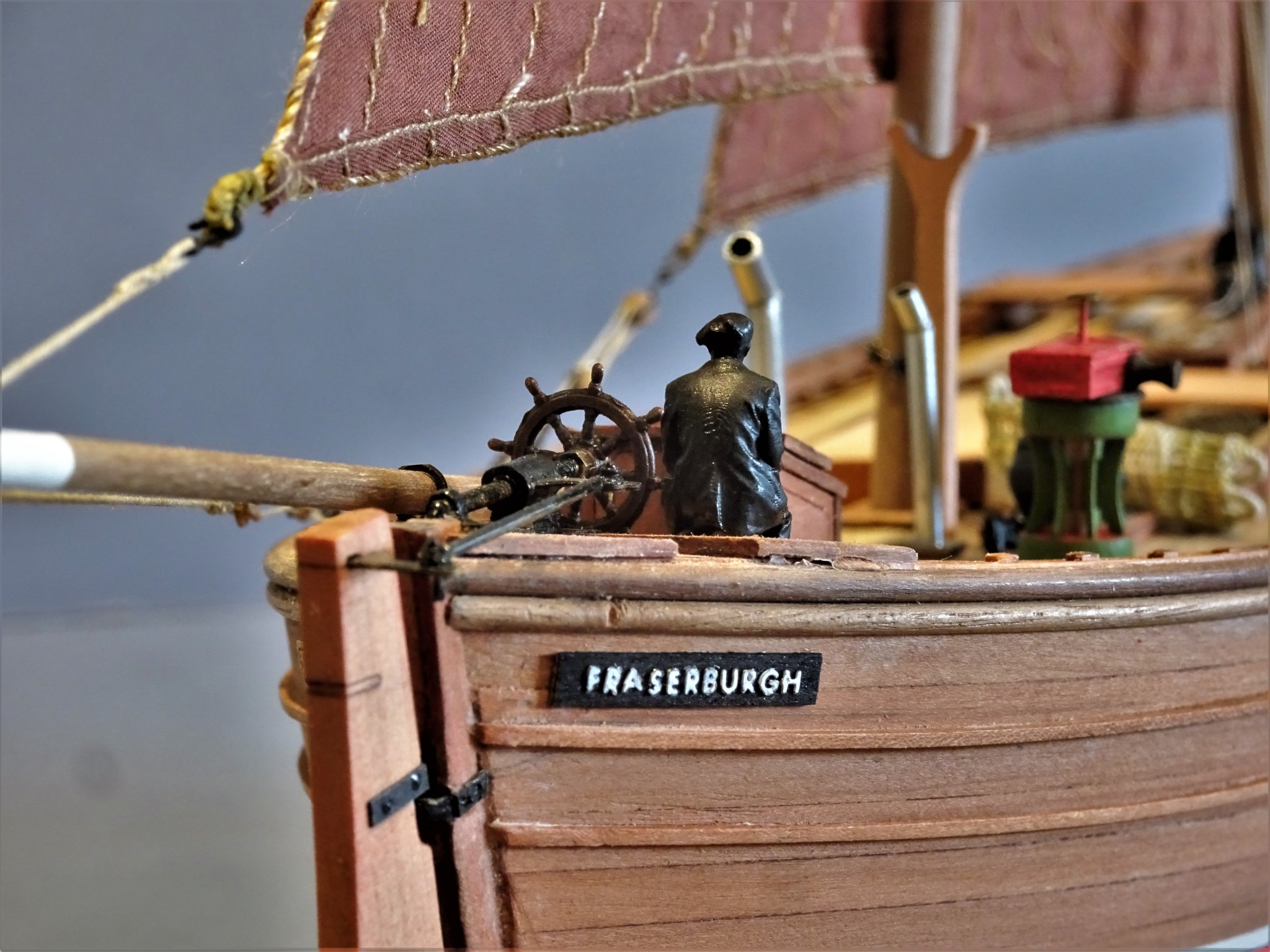
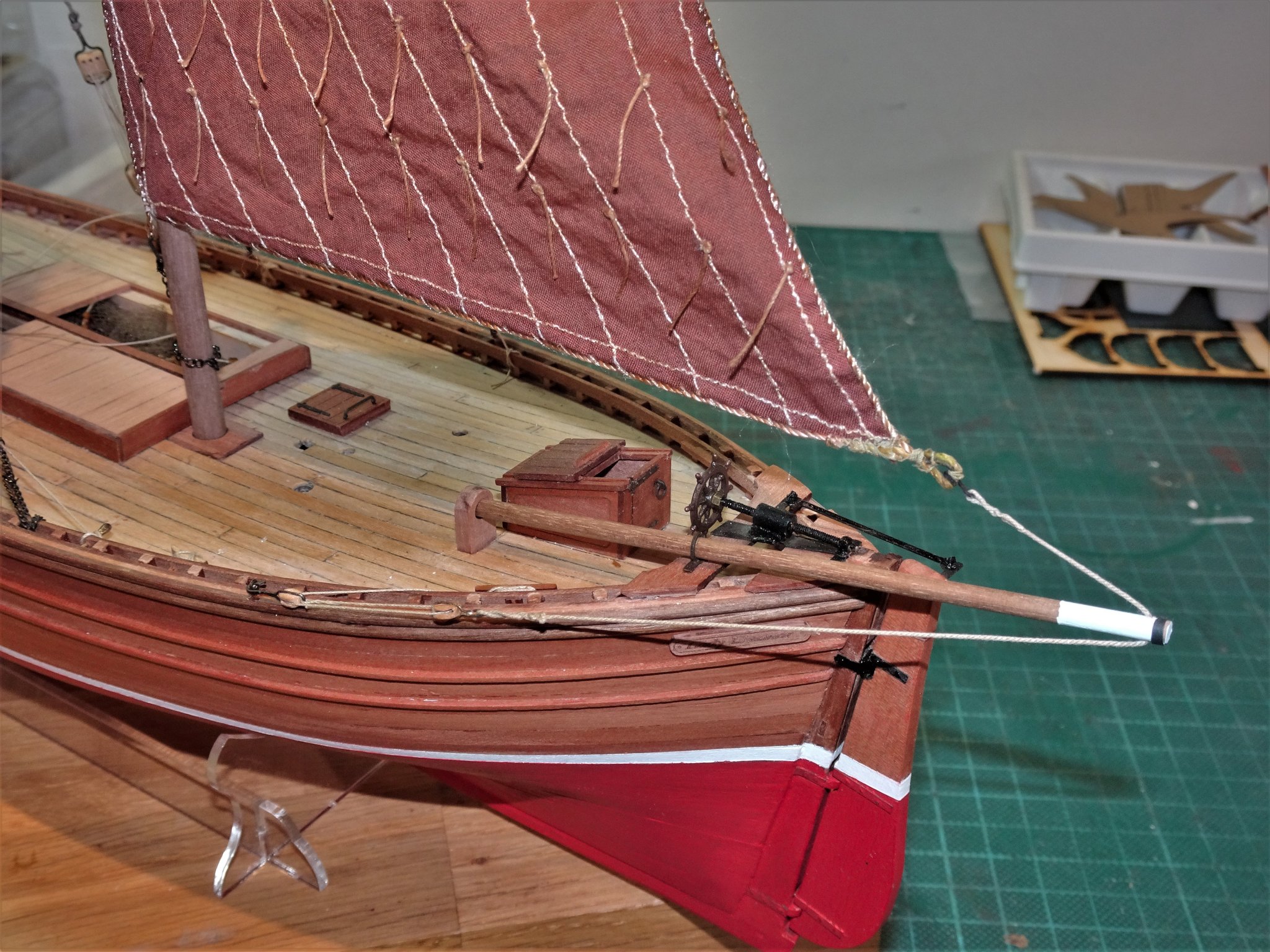
Muirneag 1903 – A Scottish Zulu Fishing Boat. 1:64 scale Based on the Vanguard Models Zulu Kit. I have decided to remodel the kit to represent the Muirneag, a sailing Zulu that had a working career of 36 years, being broken up in 1947. Zulu seems a strange name for a Scottish fishing boat type, but came about because it was first developed at the time of the Zulu wars. It was a hybrid fishing vessel, taking the best qualities of the Scaffie (sharply raking stern) and the Fifie (vertical bow) Many Zulu’s were converted to steam but Muirneag continued as a sailing drifter to the end of her career. I prefer to model an actual subject and the kit represents a large Zulu boat prevalent at the very end of their development in the early 20c with a length of some 80 feet, the Muirneag of 1903 is a prime example, and the kit fits the bill for modification. A comparison of the kit plans and those of the Muirneag, confirms that the major dimensions are comparable, and the deck layout and fittings are pretty much the same with only minor variances which won’t present any difficulties to address. I don’t have the actual masting and yard dimensions for Muirneag but I do have details for other large Fifie/ Zulu boats which are not very different from the kit provided detail, so there should not be any issues with fitting the kit provided sail set. There is a lot of information about Muirneag: Large scale, highly detailed plans by Harold Underhill, and a couple of builds based on these plans that provide excellent photos. Muirneag built by Gordon Williams who recorded his build in Model Shipwright No’s 143 and 144 and has online details of his build. http://www.muirneag.net/ A Muirneag model built by Jan van den Heuvel with excellent detail photos. https://www.modelships.de/Muirneag_J_v_d_Heuvel/Muirneag_J_v_d_Heuvel_eng.htm There are photos of a Muirneag model in the NMM built by Geoge MacLeod https://collections.rmg.co.uk/collections/objects/65970.html With all this information addressing any simplifications necessitated by the kit format is made a whole lot easier. My initial research on the Fifie will also pay dividends when it comes to the Zulu and save some of the initial head scratching I had with the Fifie build. B.E. 12/08/20
- 261 replies
-
- 17
-
-
- muirneag
- vanguard models
- (and 2 more)
-
Thank you, mugje, Glenn, Bob, and Edward, much appreciated. 🙂 B.E.
- 195 replies
-
- 2
-
-
- lady eleanor
- vanguard models
- (and 1 more)
-
Thanks Derek, not smelling the Herring is one of the upsides of building 100 miles from the sea.😄 I did scale a Herring to 1:64, and then sanity was restored.🙄 I'm sticking with the Fishing theme and moving onto the Zulu. 🙂 Cheers, B.E.
- 195 replies
-
- 5
-
-
- lady eleanor
- vanguard models
- (and 1 more)
-
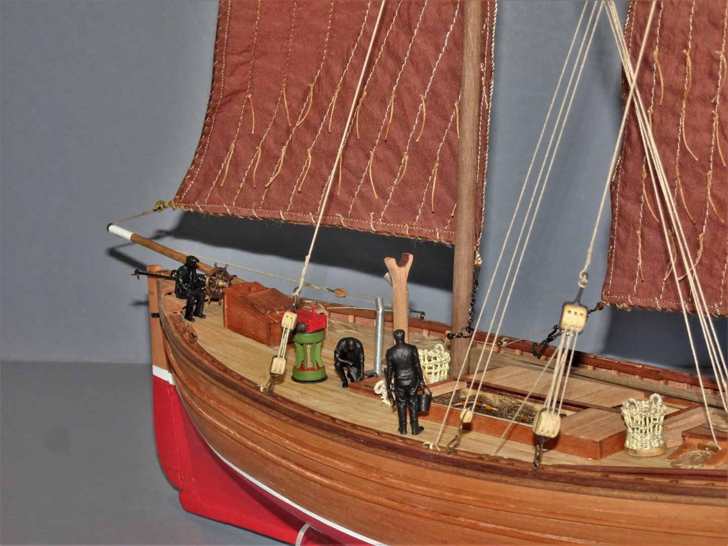
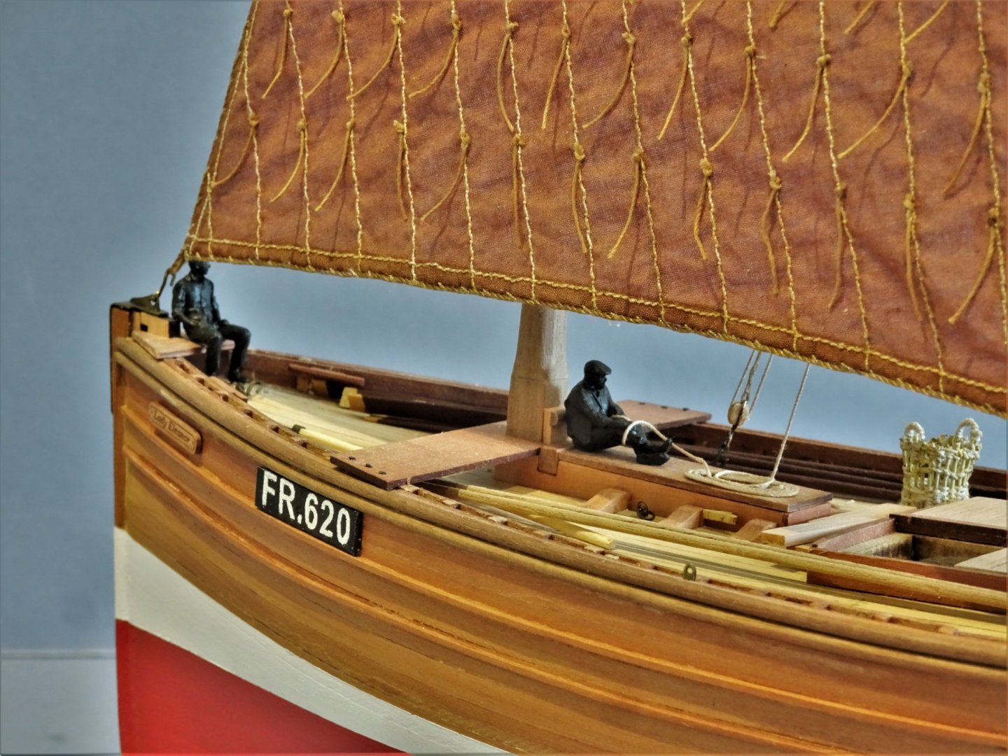
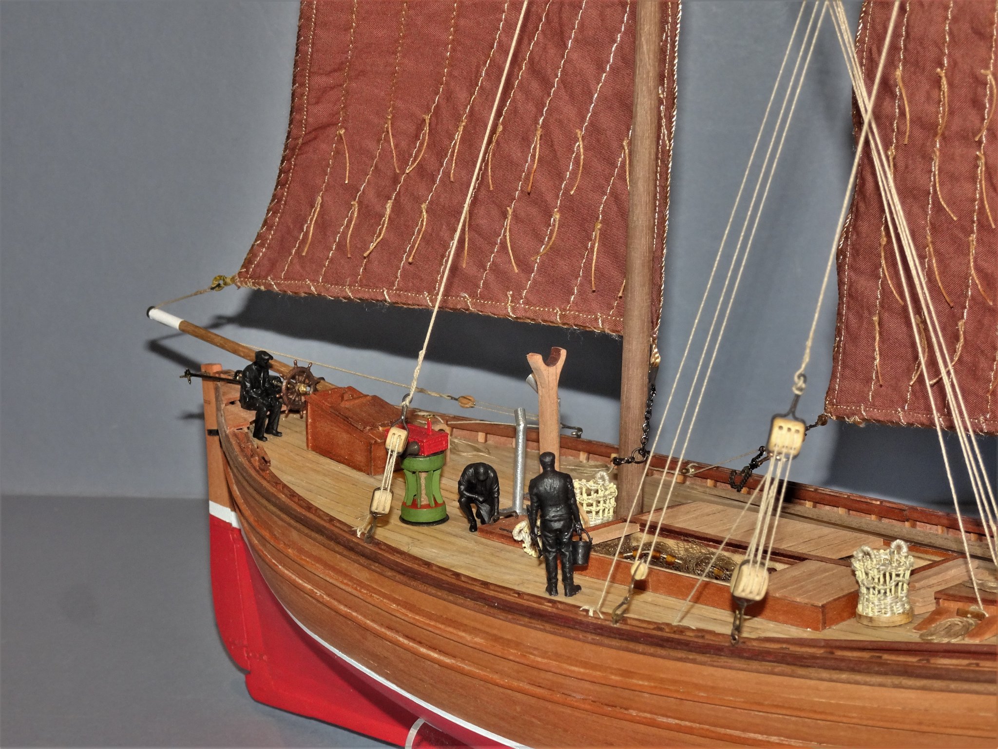
Thank you Michael, Yves, Grant, and Bob,and for the likes. @ Bob - The crew are Modelu 3d printed figures. They are primarily Model railway figures which are produced in all the Rail scales, including S scale which is 1:64. They are really finely detailed, best I’ve seen; not cheap at £7.40 each but they are suitable for the late 19th/early 20thc period. Just right for a model such as this. Regards, B.E.
- 195 replies
-
- 2
-
-
- lady eleanor
- vanguard models
- (and 1 more)
-
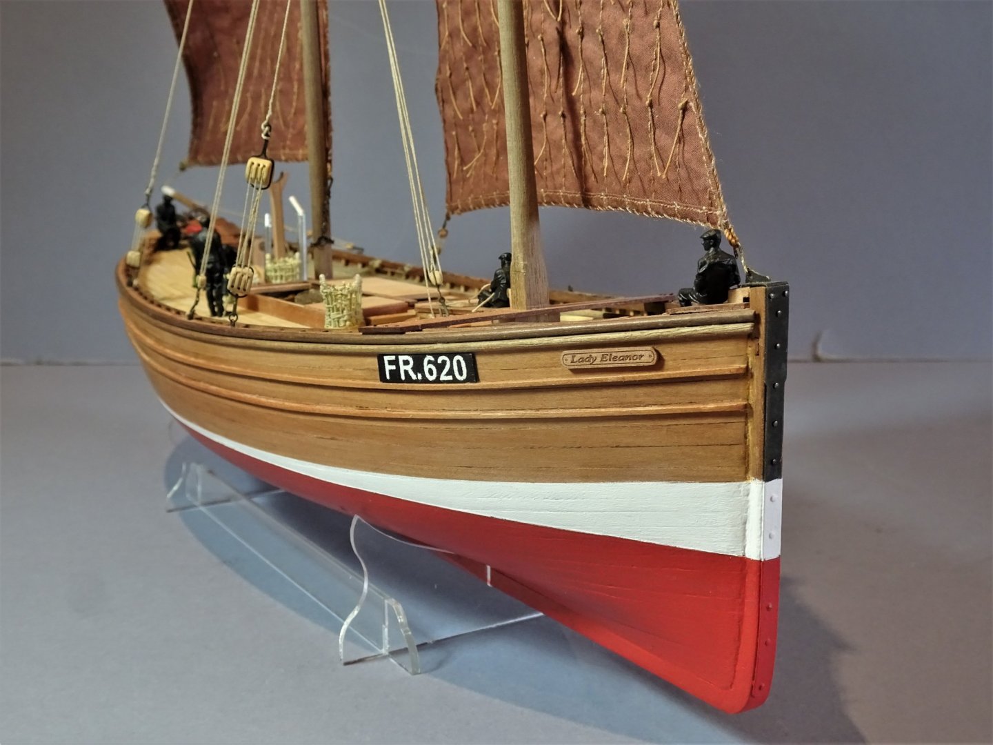
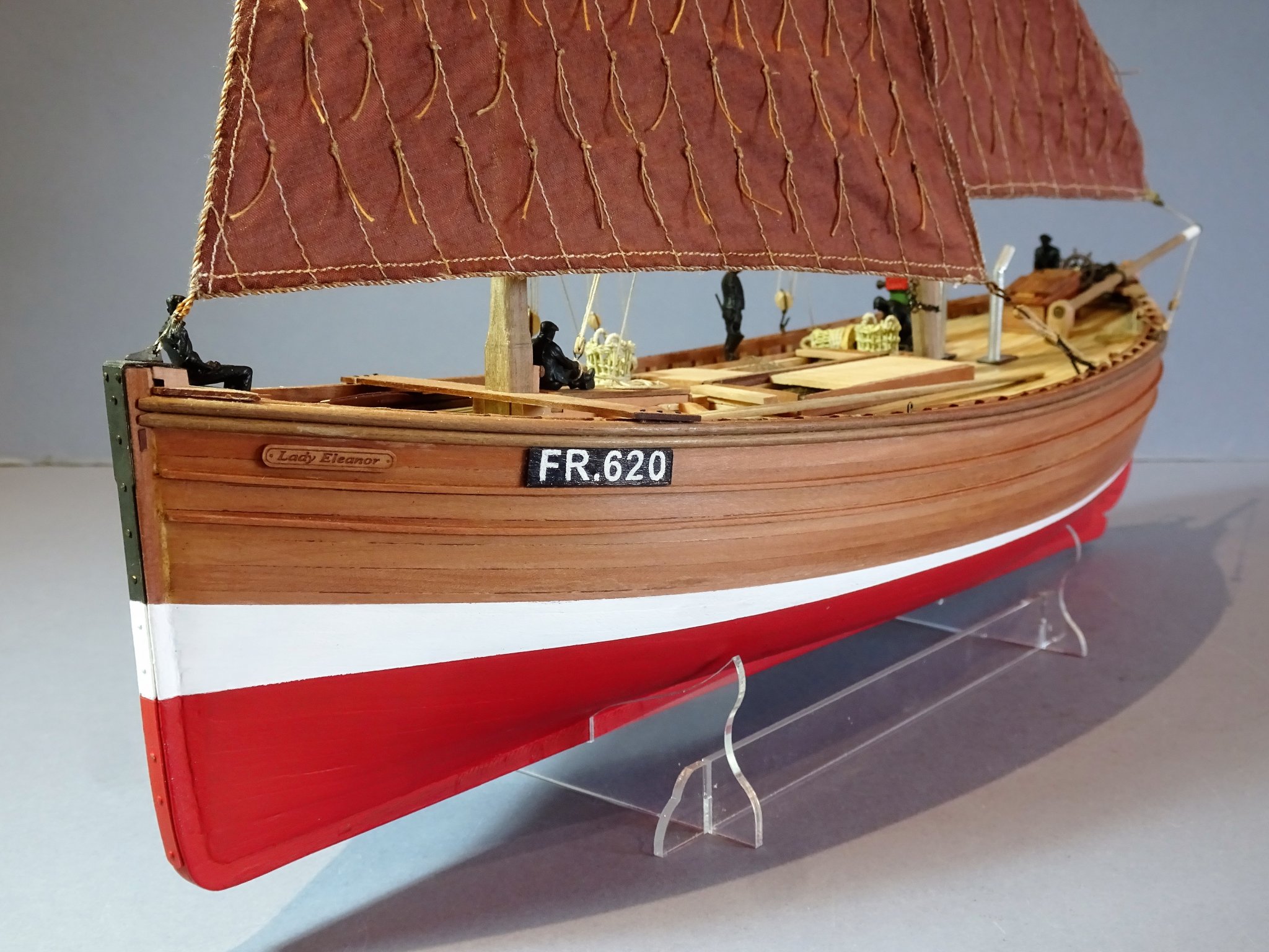
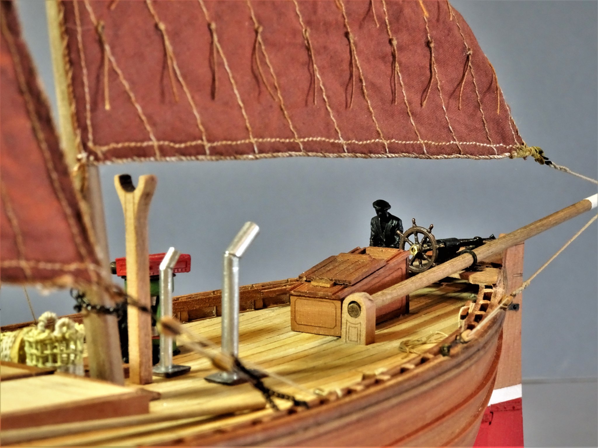
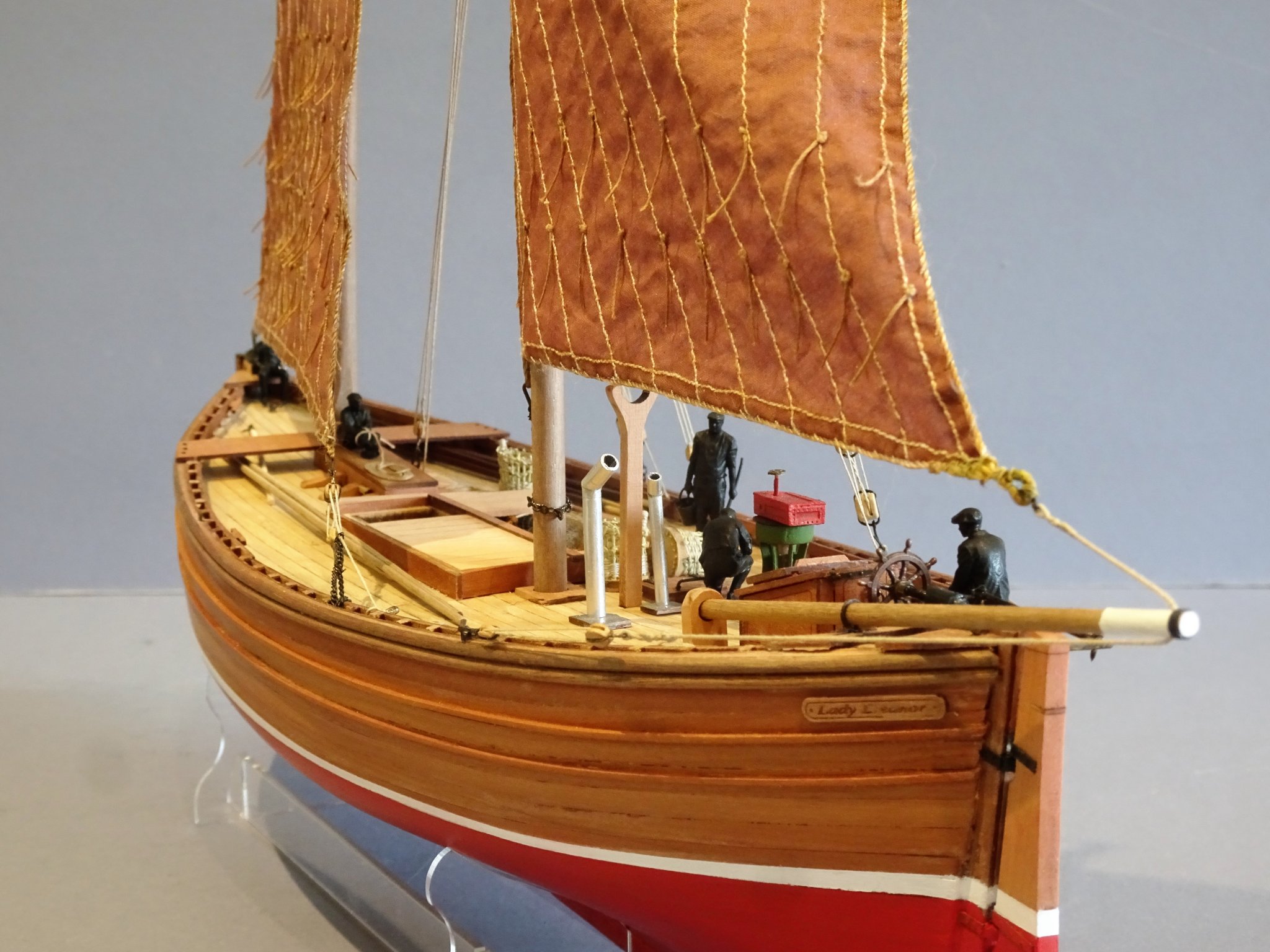
Thank you Bob, I'm sure you will enjoy building Fifie🙂 Post 31 The completed model So after around three months Fifie is completed. Starting with some close-up shots. 6552 6555 6571 6549 6545 6572 6561 6562 6563 6566(2) 6540 6543(2) 6541(2) 6538(2) 6569(2) Thoughts on the Fifie kit I have thoroughly enjoyed building this kit, perfect for a novice build, but offering plenty of scope to enhance and add extra detail. As with all of Chris’s kit offering it makes up into a very attractive model, and one that will be fairly easy to keep dust free without the need to cover. On my model very little is glued down and it could be stripped back down to deck level in a short time, pretty much as on the real thing. Being of fore/aft rigging the model takes up only a modest space and makes for a nice decorative feature in a domestic setting. For the new builder, I would say go for it, a great introduction to ship modelling. For the more experienced builder, it provides a short time interval build, a relaxing change from perhaps more involved projects. B.E. 07/08/20
.thumb.JPG.87cd860cbc8bf7bd99fabea432dae95e.JPG)

.thumb.JPG.caa519ac0952a943511e0ffe5925e7db.JPG)
.thumb.JPG.37be7b98b865cca3c99adeaa2bbf788d.JPG)


.thumb.JPG.00c6cc1c5cce2437727f6aab90928c70.JPG)
.thumb.JPG.4d705691a44ef2e60b4fd75e7b60c151.JPG)

- 195 replies
-
- 25
-
-
- lady eleanor
- vanguard models
- (and 1 more)
-
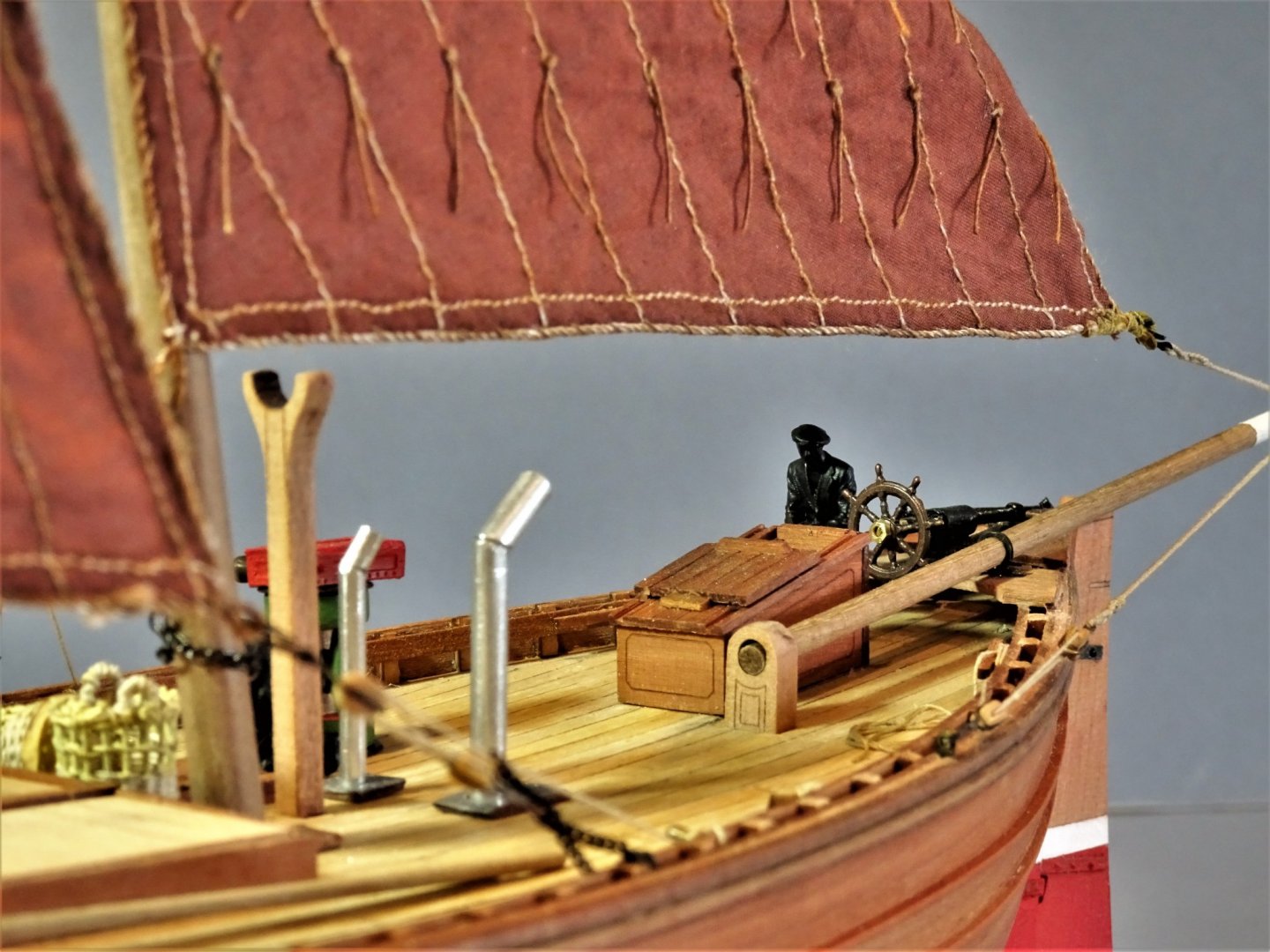
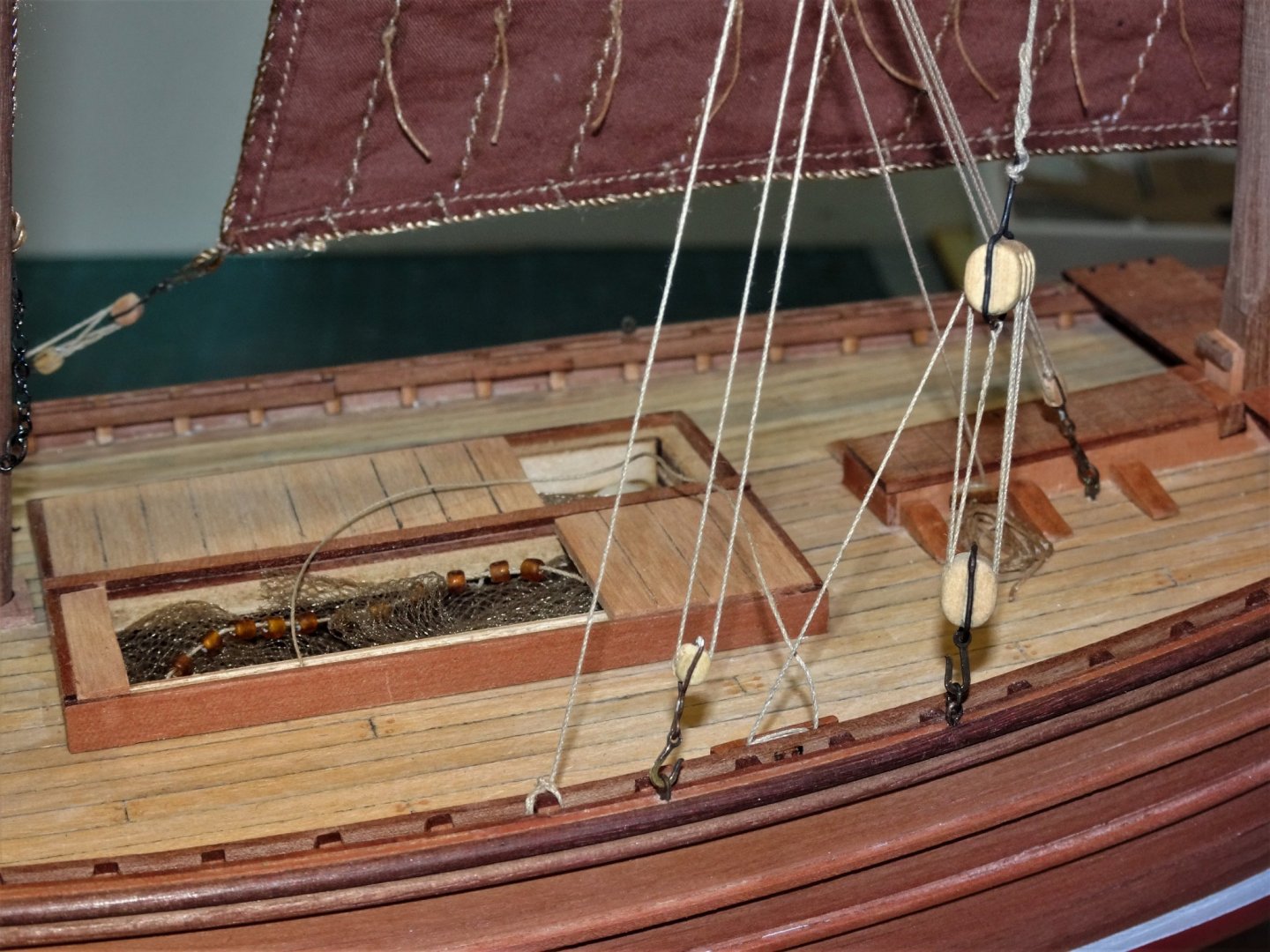
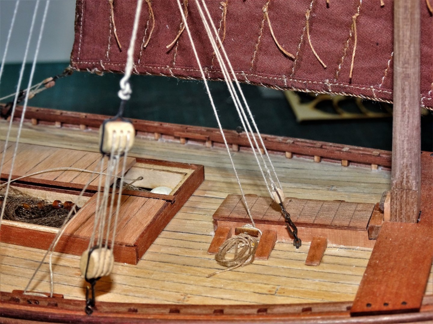
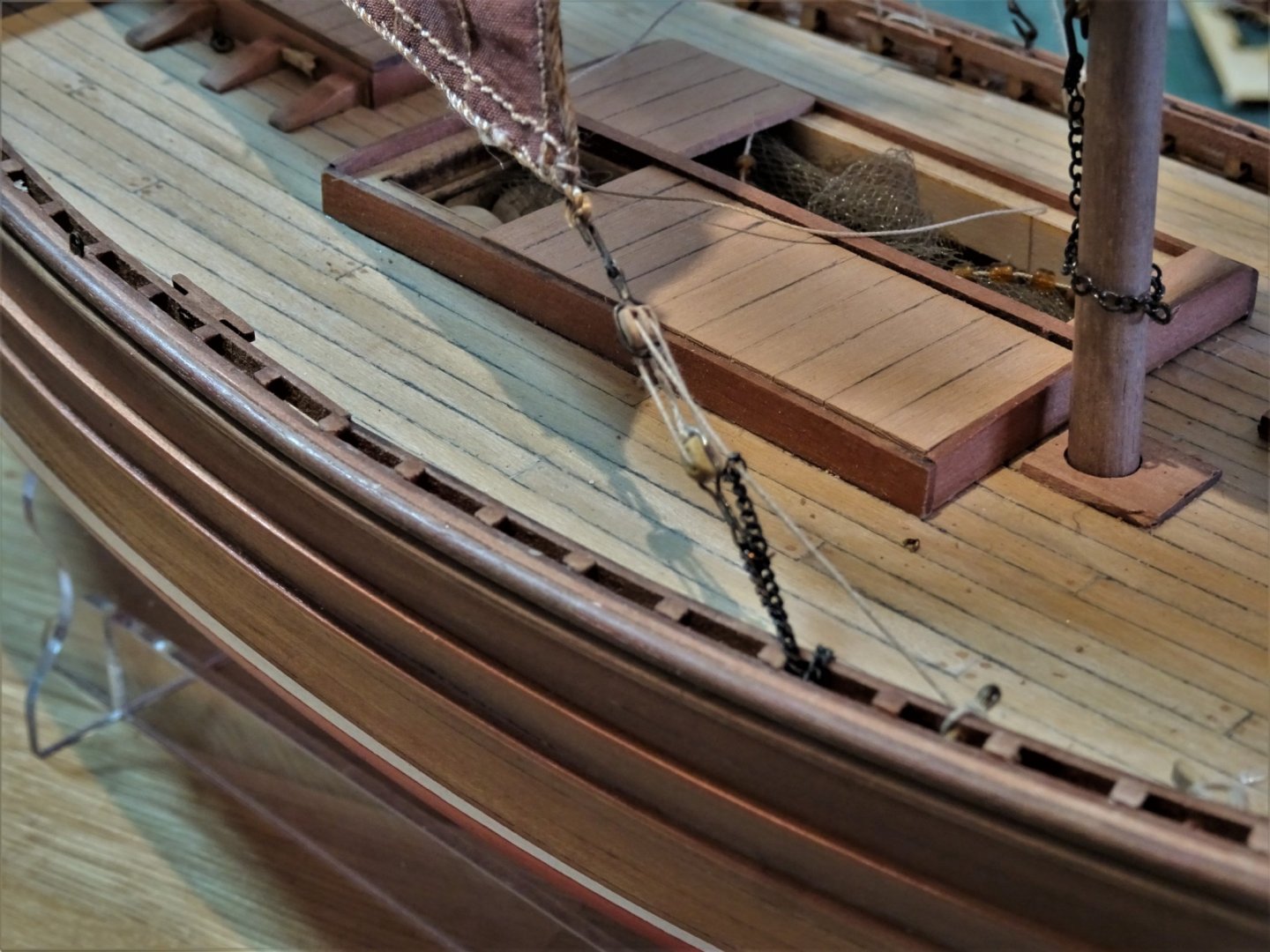
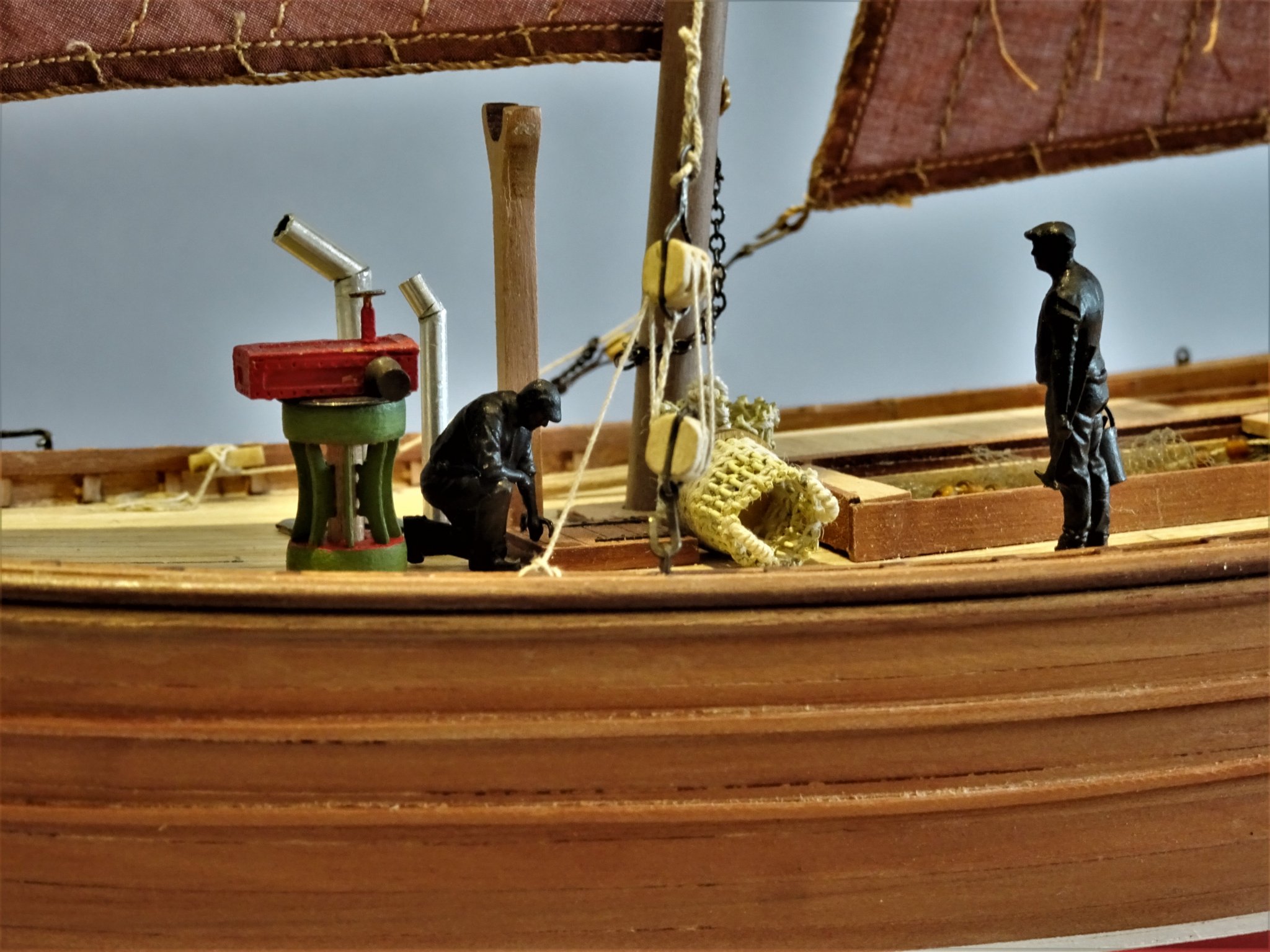
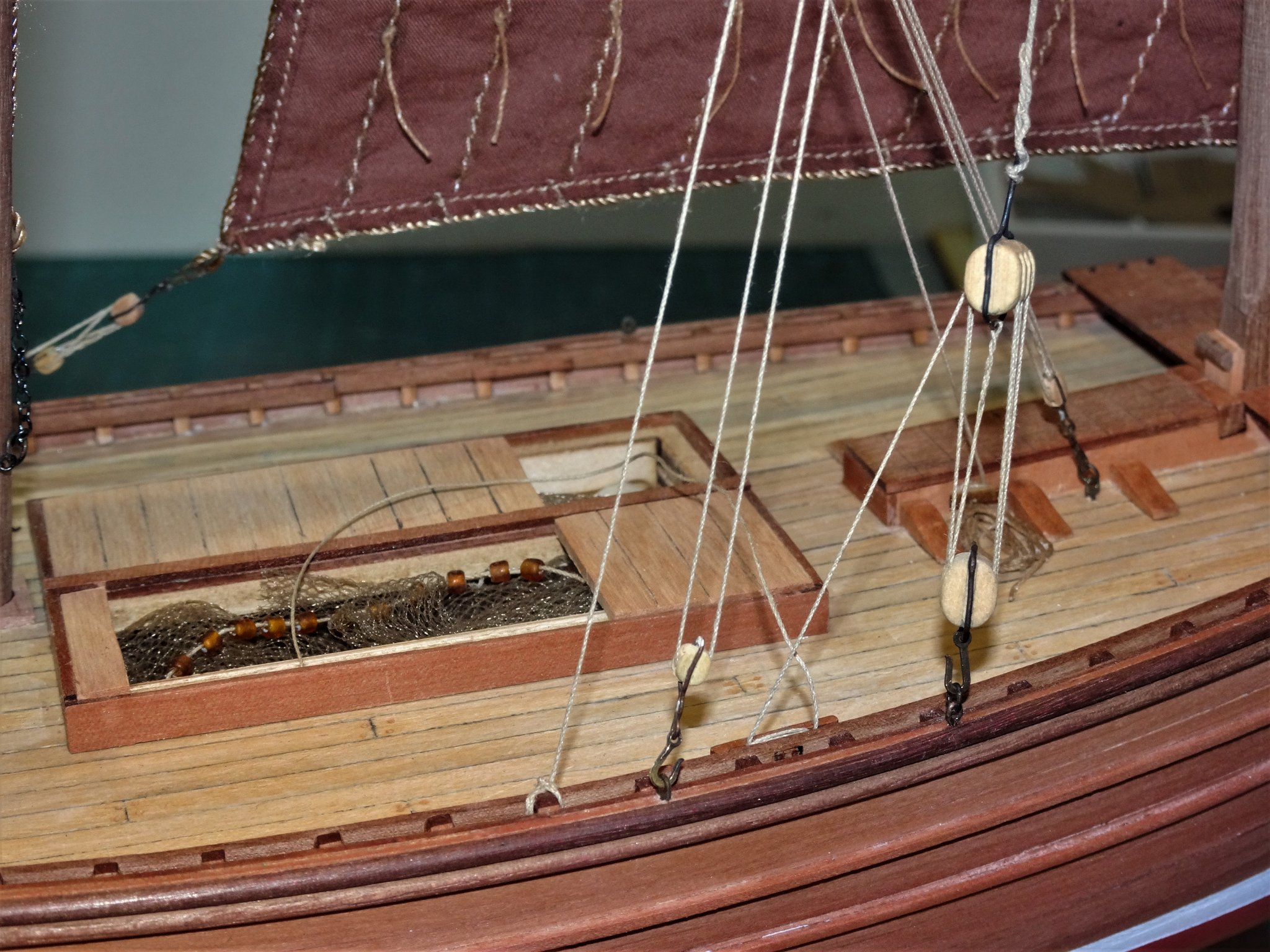
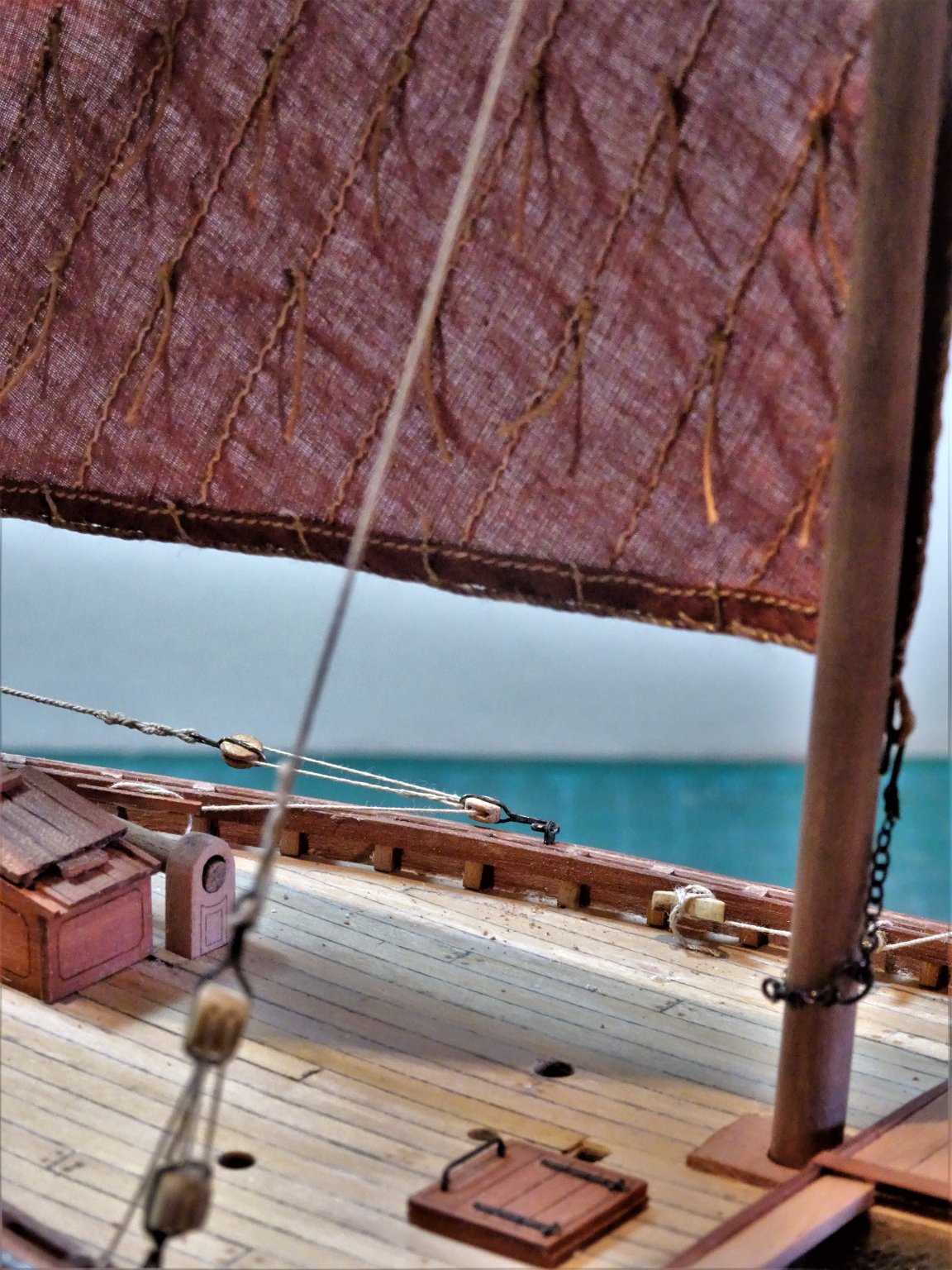
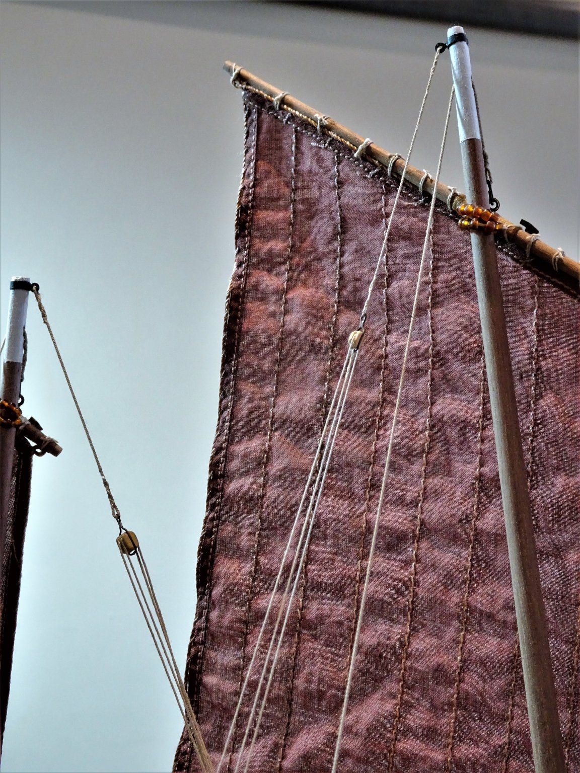
Post 30 Completing the rigging. With the arrival of fresh rigging supplies from Syren I can now complete the task. The Fore sheet The Reaper has the sheets leading directly to the port or starboard sides, depending on how the sail is set. I have taken my lead from the arrangement shown on the Underhill plan for the Zulu Muirneag. 6506 The sheet has a 3mm double block hooked to the clew, with the tackle running thro’ a 3mm single block attached by chain to the portside stringer with the running line secured around a belay pin, and tied off at a cleat 0.20mm line. Mizen sail sheet This is taken to the Portside as with the Reaper. 6513 Outboard set up of the Mizen sheets. 6525 Inboard view of the Mizen Sheets. Burton Pendents The Mizen pendent with a luff tackle is secured in the deck adjacent to the mast partners (skegs) and the fall belayed to a cleat in the partners. 6501 I didn’t glue the masts in their housings, so I fitted the Burton pendent before the Mizen sheets to secure the forward angle of the mast. Fore-mast Burton Pendent. This is the last piece of rigging fitted to the model. 6500 Rigged to the starboard side, aft of the Halyards. 6529 Masthead view of both Fore and Mizen Burton Pendents. The falls of the tackles were separately made and lightly glued to the deck. 6514 The fittings are now ready to go back on the deck. I think Fishing boat models lend themselves and benefit from a bit of dressing up. The Fifie otherwise only has the pretty little steam capstan to provide deck interest. 6497(2) These additional fittings represent the usual equipment carried on Fifie’s, and steam pipes would normally be found for the Galley stove, and steam Capstan. Netting and floats have already been installed in the Fish Hold. B.E. 06/08/20
.thumb.JPG.55bdabf0287163a5f760c79798e0e7e7.JPG)

.thumb.JPG.49afb4efff27e1085178594d36e02b5c.JPG)

- 195 replies
-
- 12
-
-
- lady eleanor
- vanguard models
- (and 1 more)
-
She's looking superb Derek, and great work on the tackle rigging. That Quad-hands tool looks an excellent investment, I'm tempted.🙂 Cheers, B.E.
-
Wonderful, we’ve not had neighbours like that for some 1500 years in ‘old’ England. B.E.
- 195 replies
-
- 2
-
-
- lady eleanor
- vanguard models
- (and 1 more)
-
Good to hear from you Martin, hope you and Mrs W are settling into your new abode. I can't really refer to her as Mrs W of the prairies any longer, perhaps Mrs W of the Hills.😉 Connecticut looks a place I would love to live in, rural, hills, quaint places, and a historic port, and of course it is in New England, spot on 😀 Regards, B.E.
- 195 replies
-
- 2
-
-
- lady eleanor
- vanguard models
- (and 1 more)
-
I'd be very happy with that Glenn, very nice work.👍 B.E.
- 778 replies
-
- 4
-
-
- cheerful
- Syren Ship Model Company
- (and 1 more)
-
The elevation and the quoins look fine to my eye, they are very tiny in reality, but I think the guns looks better with them. B.E.
- 436 replies
-
- 3
-
-
- vanguard models
- alert
- (and 1 more)
-
In my opinion you can't beat The Cruel Sea, for a realistic depiction of the Atlantic convoy story. A stark depiction of a corvette in the uboat war. B.E.
-
Ha, Ha, fortunately on my boat they haven't started fishing yet, so a basket full of 5mm herring is thankfully not required, what a relief.😉 Still some supplies have at last arrived. 6435(2) Wire rope in 0.5mm. 0.8mm and 1mm diameters. I can now fill in my time trying to make bijou shackles to fit. 🙂 B. E. 30/07/20
.thumb.JPG.6a08e7ab340cec9cc834582724baac2f.JPG)
- 195 replies
-
- 7
-
-
- lady eleanor
- vanguard models
- (and 1 more)
-
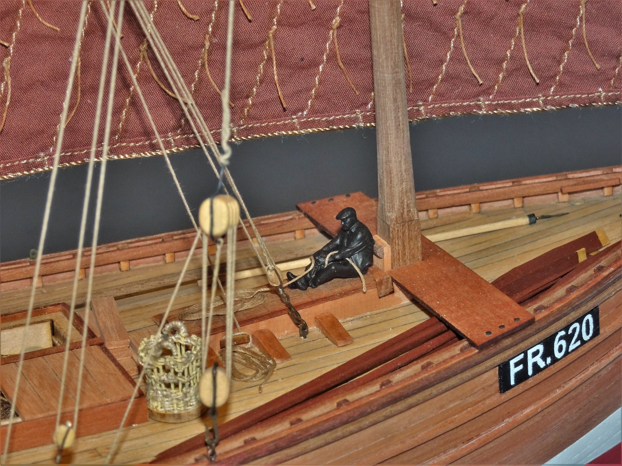
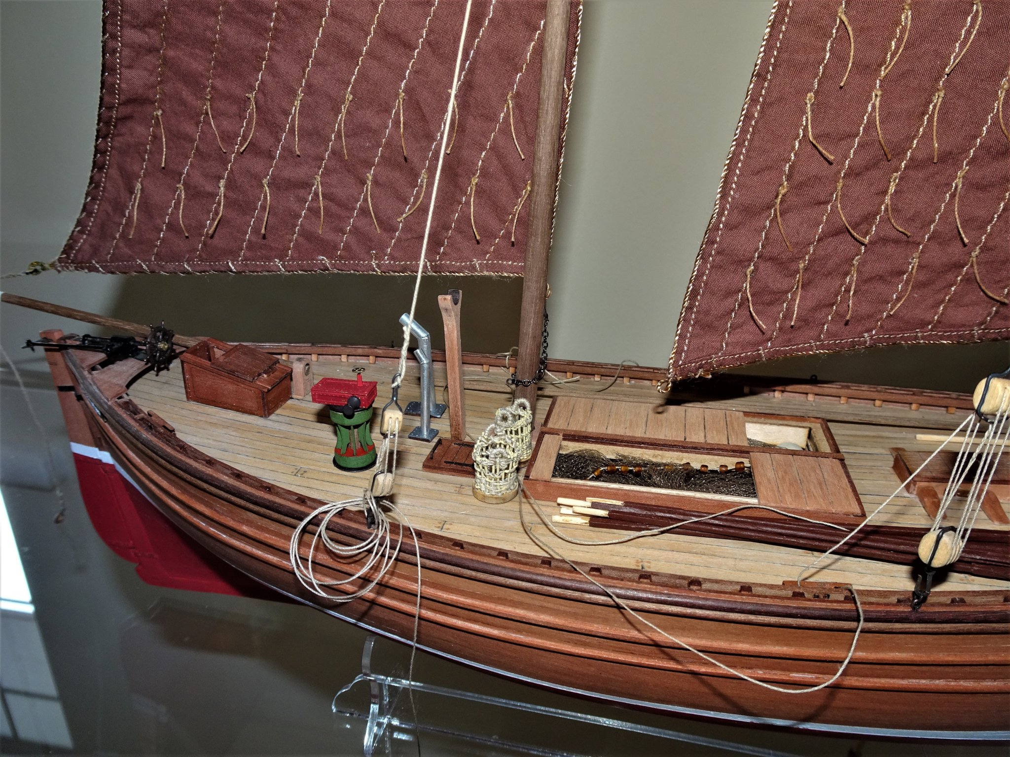
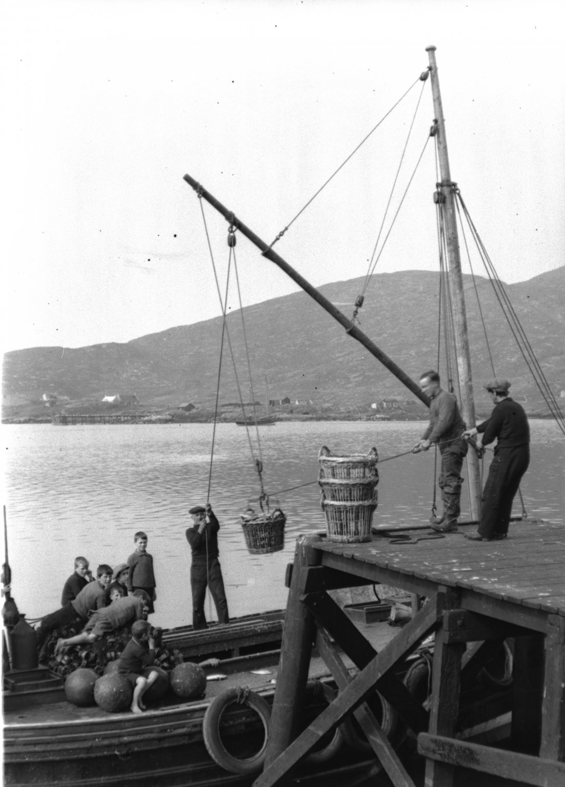
Post 29 A Basket for Fifie. Still waiting for stuff to arrive to complete Fifie, so looking around for something to work on. One of the additions that caught my eye when researching the subject is the large woven baskets used to lift the Herring catch out of the hold. Landing the catch There are called crans and have a specific and approved measure for holding a given quantity of herring. Their size was regulated and standardized by government decree as a legal measure. The 1832 Act set the cran at 30 inches high, the diameter at its widest 21.9 inches and at the base 18.9 inches – I scoured the internet for something suitable to no avail, so I started to think about how I could reproduce these for display purposes at 1:64 scale. The answer came in the form of an unlikely source – the centres out of the mast hoops supplied by Chuck for the Cheerful build. 6370(2) The centres form the base with a series of holes drilled around the circumference, 0.5mm ø brass wire is used for the frames. 6371(2) 0.1mm line is used for the weave. 6375(2) The brass rods are metal primed. 6379(2) The finished basket. The completed item measures 12mm high x 10mm diameter at the top. This equates to a size of 30” x 25”. 6386 6393 6389(2) I’m not sure that my crans would pass muster by the Scottish Fishing Authorities, but they are pretty close for scale. B.E 29/07/20
.thumb.JPG.3e18781ef5a3c91c5211f2a0ffbb727b.JPG)
.thumb.JPG.5c16edddc310f1ad3539eb0fa4956e87.JPG)
.thumb.JPG.ea4b1502553d487366b1bbd2bf7e6d26.JPG)
.thumb.JPG.41394f21d9008692ebd9132ebe8542ea.JPG)
.thumb.JPG.17d8364150951c4a19860503edca4e16.JPG)


- 195 replies
-
- 25
-
-
- lady eleanor
- vanguard models
- (and 1 more)
-
Well done Jeff, completing a model you're pleased with is the hook that keeps you involved in the hobby. One of the benefits of the Fifie model is that it is easy to keep clean and can be displayed without a case. Cheers, B.E.
- 38 replies
-
- 3
-
-
- vanguard models
- fifie
- (and 2 more)
-
Thank you Nils, Thomas, and Rusty, Alert makes up into a very attractive model One final tweak before the cover goes on, I utilised the NMM plan of Alert to cover the large expanse of varnished wood on the base. 6354(3) 6357(2) Improves the effect I think. Regards, and thank you all for taking an interest in this build. B.E 28/07/20
.thumb.JPG.dbae6daac75bb88e91e16d9fbc515f36.JPG)
.thumb.JPG.e339be0090d7ccc3602b7a3fcf10ab8f.JPG)
- 335 replies
-
- 13
-
-
- alert
- vanguard models
- (and 1 more)
-
Thank you Bob, kind of you to say so. Not so sure about definitive, but I do hope my kit interferences provide some ideas that may be of use to my fellow modellers. 🙂 I’m resisting the temptation to start the Zulu before I have done with the Fifie but it shouldn’t be long. Regards, B.E.
- 195 replies
-
- 3
-
-
- lady eleanor
- vanguard models
- (and 1 more)
-
There was a protocol for carriage and inboard works, red Ochre mostly up to the late 18thc , with yellow Ochre coming in around the start of the 19thc. I don’t think there was a strict protocol for truck colour, on my Pegasus build I left them natural, as they are on Victory today. On Alert with the shade of red I was using I just thought they looked better painted, nothing more involved than that.🙂 I also painted them red on my Cheerful cutter build, for the same reason. Regards, B.E.
- 335 replies
-
- 1
-
-
- alert
- vanguard models
- (and 1 more)
.JPG.ff1d375ed473803cd664a7a8cc14a26c.JPG)
.JPG.9fc3588fce4332719f0ab43a646069d6.JPG)
.JPG.7a63b04565db7cee662ba98165814f20.JPG)

.JPG.ea75c51c4ed130cb7563ddbe09bd7dbd.JPG)
.JPG.1fc22fb3bc89f8fb6b6bbc55b787558c.JPG)

.JPG.b314b03c312c17dca40c3f39aa3bce7d.JPG)


.JPG.3a99d60de449ba7bb4be4444414e7e07.JPG)
.JPG.2a535eb01a862a3636823f449990308e.JPG)
.JPG.7369b3b4c2f1cf4de4fdb7b90539c0da.JPG)
.JPG.8eb9008e7f5641e61d81afbf2af5ad05.JPG)
.JPG.d31c1f18a961698a6eddc07037658aa1.JPG)
.JPG.10a61e705fe611d8efaa389af413aedd.JPG)

.JPG.1b33bae5343355f7313e4545c33d17c5.JPG)
.JPG.b6f5fd8930cdbfa98270e521e33baed6.JPG)
.JPG.d34a862f062ce9280054aeb9fd79a0bb.JPG)